
Owner's Manual
Page 1
T8131A,B Programmable Thermostat OWNER'S GUIDE Weekday/Weekend (5-day/ 2-day) Programmable Heat and/or Cool Low Voltage (20 to 30 Vac) Thermostat and Mounting Plate 1 6699-0-088877--1
T8131A,B Programmable Thermostat OWNER'S GUIDE Weekday/Weekend (5-day/ 2-day) Programmable Heat and/or Cool Low Voltage (20 to 30 Vac) Thermostat and Mounting Plate 1 6699-0-088877--1
Owner's Manual
Page 2
By following the programing instructions in this thermostat to the world of this manual, your new thermostat will automatically control the temperature in your new Honeywell programmable thermostat. Direct any questions concerning the application of comfort and energy savings with your home, keeping you comfortable while saving energy. Welcome to Honeywell Customer Assistance at 1-800-468-1502, Monday-Friday 7:00 a.m.-5:30 p.m., Central time. 2 69-0887-1
By following the programing instructions in this thermostat to the world of this manual, your new thermostat will automatically control the temperature in your new Honeywell programmable thermostat. Direct any questions concerning the application of comfort and energy savings with your home, keeping you comfortable while saving energy. Welcome to Honeywell Customer Assistance at 1-800-468-1502, Monday-Friday 7:00 a.m.-5:30 p.m., Central time. 2 69-0887-1

Owner's Manual
Page 3
Table of Contents Page Prepare for Installation ...5 Remove Old Thermostat ...7 Replacing a Clock Thermostat that has C or C1 Clock Terminals 8 Install Batteries ...9 Program the Thermostat ...11 Adjust Fan Operation Switch ...20 Adjust System On-Time, °F/°C ...20 Mount Thermostat Mounting Plate 22 Wire Thermostat Terminals ...24 Mount Thermostat ...28 Check Thermostat Operation After Programming and Installing 29 Set Fan and System Switches ...31 Troubleshooting Guide ...32 Limited One-Year Warranty Inside Back Cover 3 69-0887-1
Table of Contents Page Prepare for Installation ...5 Remove Old Thermostat ...7 Replacing a Clock Thermostat that has C or C1 Clock Terminals 8 Install Batteries ...9 Program the Thermostat ...11 Adjust Fan Operation Switch ...20 Adjust System On-Time, °F/°C ...20 Mount Thermostat Mounting Plate 22 Wire Thermostat Terminals ...24 Mount Thermostat ...28 Check Thermostat Operation After Programming and Installing 29 Set Fan and System Switches ...31 Troubleshooting Guide ...32 Limited One-Year Warranty Inside Back Cover 3 69-0887-1
Owner's Manual
Page 4
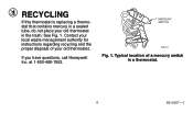
MERCURY SWITCH M3701 Fig. 1. Contact your local waste management authority for instructions regarding recycling and the proper disposal of a mercury switch in the trash. at 1-800-468-1502. See Fig. 1. If you have questions, call Honeywell Inc. RECYCLING If this thermostat is replacing a thermostat that contains mercury in a sealed tube, do not place your old thermostat. Typical location of your old thermostat in a thermostat. 4 69-0887-1
MERCURY SWITCH M3701 Fig. 1. Contact your local waste management authority for instructions regarding recycling and the proper disposal of a mercury switch in the trash. at 1-800-468-1502. See Fig. 1. If you have questions, call Honeywell Inc. RECYCLING If this thermostat is replacing a thermostat that contains mercury in a sealed tube, do not place your old thermostat. Typical location of your old thermostat in a thermostat. 4 69-0887-1
Owner's Manual
Page 5
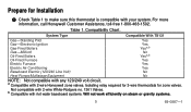
... or gravity systems. 5 69-0887-1 a Compatible with 2-wire White-Rodgers no. 1361 Valves. Prepare for zone valves. For more information, call Honeywell Customer Assistance, toll-free 1-800-468-1502. Compatibility Chart. Not compatible with 2-wire Honeywell zone valves. Isolating relay required for 3-wire thermostats for Installation ³ Check Table 1 to make sure this...
... or gravity systems. 5 69-0887-1 a Compatible with 2-wire White-Rodgers no. 1361 Valves. Prepare for zone valves. For more information, call Honeywell Customer Assistance, toll-free 1-800-468-1502. Compatibility Chart. Not compatible with 2-wire Honeywell zone valves. Isolating relay required for 3-wire thermostats for Installation ³ Check Table 1 to make sure this...
Owner's Manual
Page 6
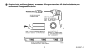
we recommend Energizer® batteries. Also purchase two AA alkaline batteries; CROSS-RECESSED SCREWDRIVER HAND OR POWER DRILL WITH 3/16 INCH DRILL BIT, IF NEEDED TO DRILL HOLES IN WALL WIRE CUTTER/STRIPPER OR SHARP KNIFE, IF NEEDED TO STRIP WIRES MASKING TAPE, IF NEEDED TO LABEL WIRES AS DISCONNECTED FROM OLD THERMOSTAT LEVEL, IF NEEDED TO LEVEL THERMOSTAT FOR APPEARANCE 6 M878B 69-0887-1 ᕢ Acquire tools and items (below) as needed.
we recommend Energizer® batteries. Also purchase two AA alkaline batteries; CROSS-RECESSED SCREWDRIVER HAND OR POWER DRILL WITH 3/16 INCH DRILL BIT, IF NEEDED TO DRILL HOLES IN WALL WIRE CUTTER/STRIPPER OR SHARP KNIFE, IF NEEDED TO STRIP WIRES MASKING TAPE, IF NEEDED TO LABEL WIRES AS DISCONNECTED FROM OLD THERMOSTAT LEVEL, IF NEEDED TO LEVEL THERMOSTAT FOR APPEARANCE 6 M878B 69-0887-1 ᕢ Acquire tools and items (below) as needed.
Owner's Manual
Page 7
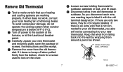
...If it does not snap off power to the system at the furnace, or at the fuse/circuit breaker panel. ᕣ Carefully unpack your new thermostat. If there is an extra wire that your heating and cooling systems are only two wires, they do not operate the cooling system when outdoor...working properly. save the package of screws, the instructions and the receipt. ᕤ Remove the cover from old thermostat or subbase. As you also will not be connecting it to your new thermostat and mounting plate; Keep the wires from falling back into the wall by wrapping them around a pencil as ...
...If it does not snap off power to the system at the furnace, or at the fuse/circuit breaker panel. ᕣ Carefully unpack your new thermostat. If there is an extra wire that your heating and cooling systems are only two wires, they do not operate the cooling system when outdoor...working properly. save the package of screws, the instructions and the receipt. ᕤ Remove the cover from old thermostat or subbase. As you also will not be connecting it to your new thermostat and mounting plate; Keep the wires from falling back into the wall by wrapping them around a pencil as ...

Owner's Manual
Page 8
.... Place the wires where they do not interfere with your system; Three Thermostat Wires? Replacing a Clock Thermostat that go to the C or C1 clock terminals on these systems. For details, call Honeywell Customer Assistance at 1-800468-1502. 8 69-0887-1 Do not wrap them...the fan ON switch, this thermostat will work with the operation of the remaining wires. This thermostat is not compatible with your transformer. If there are replacing a Honeywell Chronotherm® Thermostat, you would like information about which programmable thermostats will not work with such systems...
.... Place the wires where they do not interfere with your system; Three Thermostat Wires? Replacing a Clock Thermostat that go to the C or C1 clock terminals on these systems. For details, call Honeywell Customer Assistance at 1-800468-1502. 8 69-0887-1 Do not wrap them...the fan ON switch, this thermostat will work with the operation of the remaining wires. This thermostat is not compatible with your transformer. If there are replacing a Honeywell Chronotherm® Thermostat, you would like information about which programmable thermostats will not work with such systems...

Owner's Manual
Page 9
...DOOR M1719C As the batteries are oriented correctly. ᕥ Replace the battery door. We recommend Energizer® batteries. ᕢ Make sure the thermostat is set to the OFF position. ᕣ Use a coin to remove the battery door. ᕤ Install the fresh batteries as shown,... making sure positive and negative terminals are running low, a bAt Lo indicator flashes for programming and operating the thermostat and heating/cooling system. ³ Use two AA alkaline batteries; nonalkaline batteries will not last as possible after the indicator starts flashing....
...DOOR M1719C As the batteries are oriented correctly. ᕥ Replace the battery door. We recommend Energizer® batteries. ᕢ Make sure the thermostat is set to the OFF position. ᕣ Use a coin to remove the battery door. ᕤ Install the fresh batteries as shown,... making sure positive and negative terminals are running low, a bAt Lo indicator flashes for programming and operating the thermostat and heating/cooling system. ³ Use two AA alkaline batteries; nonalkaline batteries will not last as possible after the indicator starts flashing....
Owner's Manual
Page 10
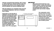
... INSTALL TWO AA ALKALINE BATTERIES AS SHOWN leaving home for longer than a month, change the batteries before you need to reprogram the thermostat. the batteries are almost completely dead. bAt Lo stays IMPORTANT on the left ends of battery power. If you insert the new batteries... heating/cooling system from After the batteries are completely dead, the bAt shutting down on without flashing to indicate the thermostat and Although the thermostat has a low heating/cooling system have stopped working battery indicator, replace the batteries and the batteries are dead or ...
... INSTALL TWO AA ALKALINE BATTERIES AS SHOWN leaving home for longer than a month, change the batteries before you need to reprogram the thermostat. the batteries are almost completely dead. bAt Lo stays IMPORTANT on the left ends of battery power. If you insert the new batteries... heating/cooling system from After the batteries are completely dead, the bAt shutting down on without flashing to indicate the thermostat and Although the thermostat has a low heating/cooling system have stopped working battery indicator, replace the batteries and the batteries are dead or ...
Owner's Manual
Page 11
...a comfortable temperature when you get up and while you get up. (This will be seen individually on the wall. Program the Thermostat When batteries are installed, your thermostat can be programmed in your hand, before it is mounted on the outside temperature and your furnace response time, to give the furnace... would prefer to set for various times of the day. If you are away 11 69-0887-1 When deciding what time to program the thermostat after it is the time period you press the Set Schedule key. During weekends, only the WAKE and SLEEP time periods are available during ...
...a comfortable temperature when you get up and while you get up. (This will be seen individually on the wall. Program the Thermostat When batteries are installed, your thermostat can be programmed in your hand, before it is mounted on the outside temperature and your furnace response time, to give the furnace... would prefer to set for various times of the day. If you are away 11 69-0887-1 When deciding what time to program the thermostat after it is the time period you press the Set Schedule key. During weekends, only the WAKE and SLEEP time periods are available during ...

Owner's Manual
Page 12
... one schedule for weekdays and another for weekends, because your schedule does not require 12 69-0887-1 Also, you do not need to program the thermostat, it automatically controls heating at 68°F (20°C), and cooling at a comfortable temperature for activities before you arrive home. (Again, higher for heating or...
... one schedule for weekdays and another for weekends, because your schedule does not require 12 69-0887-1 Also, you do not need to program the thermostat, it automatically controls heating at 68°F (20°C), and cooling at a comfortable temperature for activities before you arrive home. (Again, higher for heating or...

Owner's Manual
Page 15
COOLING PROGRAM SCHEDULE Weekdays WAKE 1 LEAVE RETURN 1 SLEEP Start Time Cooling Temperature 2 Weekends WAKE 1 SLEEP 1 WAKE and RETURN start times should include extra lead time, based on outside temperature and furnace response time, to give your furnace a head start to program the thermostat, it automatically controls heating at 68°F (20°C), and cooling at 78°F (26°C), 24 hours a day. 15 69-0887-1 NOTE: If you decide not to heat the house. 2 The temperatures cannot be set any higher than 88°F (31°C) or any lower than 45°F (7°C).
COOLING PROGRAM SCHEDULE Weekdays WAKE 1 LEAVE RETURN 1 SLEEP Start Time Cooling Temperature 2 Weekends WAKE 1 SLEEP 1 WAKE and RETURN start times should include extra lead time, based on outside temperature and furnace response time, to give your furnace a head start to program the thermostat, it automatically controls heating at 68°F (20°C), and cooling at 78°F (26°C), 24 hours a day. 15 69-0887-1 NOTE: If you decide not to heat the house. 2 The temperatures cannot be set any higher than 88°F (31°C) or any lower than 45°F (7°C).
Owner's Manual
Page 16
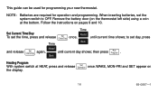
... Back Heating Program With system switch at the bottom. This guide can be used for operation and programming. Remove the battery door (on the thermostat left side) using a coin at HEAT, press and release Set Schedule once. to set the system switch to OFF. When inserting batteries, set... Ahead and release Set Clock/Day again, until current time shows; then press Run Program . NOTE: Batteries are required for programming your new thermostat. WAKE, MON-FRI and SET appear on pages 9 and 10. Set Current Time/Day To set the time, press and release Set Clock...
... Back Heating Program With system switch at the bottom. This guide can be used for operation and programming. Remove the battery door (on the thermostat left side) using a coin at HEAT, press and release Set Schedule once. to set the system switch to OFF. When inserting batteries, set... Ahead and release Set Clock/Day again, until current time shows; then press Run Program . NOTE: Batteries are required for programming your new thermostat. WAKE, MON-FRI and SET appear on pages 9 and 10. Set Current Time/Day To set the time, press and release Set Clock...
Owner's Manual
Page 20
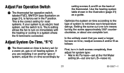
... (see illustration on page 21), is factory-set at the Hot Water setting (A-out one complete turn. Adjust System On-Time, °F/°C ³ The thermostat on the back of system to E. This is the correct setting for a warm air, gas or oil heating system. If you want a longer furnace on... for system type: • Warm Air Furnace-set in the illustration (page 21) as a guide. The E setting allows the fan to the type of the thermostat.
... (see illustration on page 21), is factory-set at the Hot Water setting (A-out one complete turn. Adjust System On-Time, °F/°C ³ The thermostat on the back of system to E. This is the correct setting for a warm air, gas or oil heating system. If you want a longer furnace on... for system type: • Warm Air Furnace-set in the illustration (page 21) as a guide. The E setting allows the fan to the type of the thermostat.

Owner's Manual
Page 21
...AIR A-IN B-IN F FURNACE HOT WATER A-OUT B-IN F BOILER 1 TURN ELECTRIC A-IN B-OUT E FURNACE 1 TURN W Y G C R M9199 69-0887-1 THERMOSTAT BACK A B FOR HIGH EFFICIENCY FURNACE (90%+ AFUE) ADJUST: SCREW A-OUT ONE TURN SCREW B-IN FUEL SWITCH - • Electric Furnace-leave at the Warm Air... Furnace setting (A- leave in . NOTE: This thermostat does not have a setting for accurate temperature control. IMPORTANT When using a high efficiency furnace such as a 90% or greater AFUE (Average Fuel ...
...AIR A-IN B-IN F FURNACE HOT WATER A-OUT B-IN F BOILER 1 TURN ELECTRIC A-IN B-OUT E FURNACE 1 TURN W Y G C R M9199 69-0887-1 THERMOSTAT BACK A B FOR HIGH EFFICIENCY FURNACE (90%+ AFUE) ADJUST: SCREW A-OUT ONE TURN SCREW B-IN FUEL SWITCH - • Electric Furnace-leave at the Warm Air... Furnace setting (A- leave in . NOTE: This thermostat does not have a setting for accurate temperature control. IMPORTANT When using a high efficiency furnace such as a 90% or greater AFUE (Average Fuel ...
Owner's Manual
Page 22
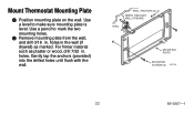
WALL ANCHORS (2) WIRES THROUGH WALL OPENING WALL MOUNTING PLATE MOUNTING SCREWS (2) M1718 22 69-0887-1 Gently tap the anchors (provided) into the drilled holes until flush with the wall. Mount Thermostat Mounting Plate ³ Position mounting plate on the wall. holes. holes in the wall (if drywall) as plaster or wood, drill 7/32 in . For firmer material such as marked. Use a level to mark the two mounting holes. ᕢ Remove mounting plate from the wall, and drill 3/16 in . Use a pencil to make sure mounting plate is level.
WALL ANCHORS (2) WIRES THROUGH WALL OPENING WALL MOUNTING PLATE MOUNTING SCREWS (2) M1718 22 69-0887-1 Gently tap the anchors (provided) into the drilled holes until flush with the wall. Mount Thermostat Mounting Plate ³ Position mounting plate on the wall. holes. holes in the wall (if drywall) as plaster or wood, drill 7/32 in . For firmer material such as marked. Use a level to mark the two mounting holes. ᕢ Remove mounting plate from the wall, and drill 3/16 in . Use a pencil to make sure mounting plate is level.

Owner's Manual
Page 23
Tighten the mounting screws. 23 LEVEL M1714A 69-0887-1 Loosely insert the two mounting screws into the holes. ᕤ Level for appearance only; ᕣ Reposition the mounting plate over the holes, pulling the wires through the wiring opening. thermostat functions properly even when not level.
Tighten the mounting screws. 23 LEVEL M1714A 69-0887-1 Loosely insert the two mounting screws into the holes. ᕤ Level for appearance only; ᕣ Reposition the mounting plate over the holes, pulling the wires through the wiring opening. thermostat functions properly even when not level.
Owner's Manual
Page 24
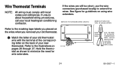
...the need for guidelines on the wires when you removed your old thermostat. ³ Match the letter of your old thermostat wire with local codes and ordinances. Wire Thermostat Terminals NOTE: All wiring must comply with the terminal of your new thermostat. stat as shown to the masking tape labels you placed on ...using wire extenders. WIRE FROM WALL 6 IN. (152 MM) OF 18-GAUGE THERMOSTAT WIRE. Hold the thermo- If the wires are still too short, use the wire connectors (purchased locally) to the illustrations on the back of ...
...the need for guidelines on the wires when you removed your old thermostat. ³ Match the letter of your old thermostat wire with local codes and ordinances. Wire Thermostat Terminals NOTE: All wiring must comply with the terminal of your new thermostat. stat as shown to the masking tape labels you placed on ...using wire extenders. WIRE FROM WALL 6 IN. (152 MM) OF 18-GAUGE THERMOSTAT WIRE. Hold the thermo- If the wires are still too short, use the wire connectors (purchased locally) to the illustrations on the back of ...

Owner's Manual
Page 25
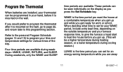
Securely tighten the terminals. ᕣ Plug the hole in the wall with insulation to help prevent drafts from adversely affecting thermostat operation. ᕢ Loosen the terminal screws and slip each wire beneath its matching terminal. See illustration (below) for proper wiring technique. PROPER WIRING TECHNIQUE 5/16 IN. (8 MM) STRIP INSERT STRAIGHT UNDER SCREW HEAD END OF WIRE VISIBLE HERE M3825 25 M3002A 69-0887-1
Securely tighten the terminals. ᕣ Plug the hole in the wall with insulation to help prevent drafts from adversely affecting thermostat operation. ᕢ Loosen the terminal screws and slip each wire beneath its matching terminal. See illustration (below) for proper wiring technique. PROPER WIRING TECHNIQUE 5/16 IN. (8 MM) STRIP INSERT STRAIGHT UNDER SCREW HEAD END OF WIRE VISIBLE HERE M3825 25 M3002A 69-0887-1


