
User Guide
Page 1
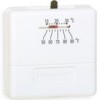
... and install. s Green light emitting diode (LED) lights when prop- CONTENTS Specifications 2 Ordering Information 2 Installation 3 Programming the Thermostat 8 Checkout and Settings 10 Troubleshooting 11 Cross Reference 12 B.M. • Rev. 61-94 • ©Honeywell Inc. 1994 • Form Number 68-0148-1 T8131C T8132C T8131/T8132 Models s HEAT-OFF-COOL system switch. s Digital...
... and install. s Green light emitting diode (LED) lights when prop- CONTENTS Specifications 2 Ordering Information 2 Installation 3 Programming the Thermostat 8 Checkout and Settings 10 Troubleshooting 11 Cross Reference 12 B.M. • Rev. 61-94 • ©Honeywell Inc. 1994 • Form Number 68-0148-1 T8131C T8132C T8131/T8132 Models s HEAT-OFF-COOL system switch. s Digital...

User Guide
Page 2
... MODELS: T8131A/T8132A Programmable Thermostats: Provide eight program keys; T8131A,B,C; OPERATING AMBIENT TEMPERATURE RANGE: 40° F to 110° F [4° C to indicate proper operation when both sides of phone directory). 2. Your local Honeywell Home and Building Control Sales ...Office (check white pages of the 24 Vac system transformer are changed. Specifications T8131B/T8132B Programmable Thermostats: Provide eight program keys;
... MODELS: T8131A/T8132A Programmable Thermostats: Provide eight program keys; T8131A,B,C; OPERATING AMBIENT TEMPERATURE RANGE: 40° F to 110° F [4° C to indicate proper operation when both sides of phone directory). 2. Your local Honeywell Home and Building Control Sales ...Office (check white pages of the 24 Vac system transformer are changed. Specifications T8131B/T8132B Programmable Thermostats: Provide eight program keys;

User Guide
Page 3
.... Reposition mounting plate over holes, pulling wires through wiring opening. Make sure installer is compatible with 2-wire Honeywell zone valves. System Type Compatible with T8131/T8132 Gas-Standing Pilot Yes Gas-Electronic Ignition Yes Gas-Fired Boilers...to prevent electrical shock or equipment damage. After completing installation, use these instructions carefully. Isolating relay required for 3-wire thermostats for appearance only; Cooling: Factory-set at average temperature. Not designed for Standardization Relay and Transformer. ACCESSORIES: 205013 ...
.... Reposition mounting plate over holes, pulling wires through wiring opening. Make sure installer is compatible with 2-wire Honeywell zone valves. System Type Compatible with T8131/T8132 Gas-Standing Pilot Yes Gas-Electronic Ignition Yes Gas-Fired Boilers...to prevent electrical shock or equipment damage. After completing installation, use these instructions carefully. Isolating relay required for 3-wire thermostats for appearance only; Cooling: Factory-set at average temperature. Not designed for Standardization Relay and Transformer. ACCESSORIES: 205013 ...

User Guide
Page 4
... MEANS AND OVERLOAD PROTECTION AS REQUIRED. T8132A,B,C INSTALLATION Fig. 3-Mounting thermostat mounting plate. T8131 Models Run the required number of wires to help prevent drafts from adversely affecting thermostat operation. PROVIDE DISCONNECT MEANS AND OVERLOAD PROTECTION AS REQUIRED. M9213 Fig.... to Figs. 5 through 11 for wiring insertion techniques. PROPER WIRING TECHNIQUE 5/16 in the wall with insulation to the thermostat location (check the appropriate wiring diagram). Loosen the terminal screws and slip each wire beneath its matching terminal. Follow instructions ...
... MEANS AND OVERLOAD PROTECTION AS REQUIRED. T8132A,B,C INSTALLATION Fig. 3-Mounting thermostat mounting plate. T8131 Models Run the required number of wires to help prevent drafts from adversely affecting thermostat operation. PROVIDE DISCONNECT MEANS AND OVERLOAD PROTECTION AS REQUIRED. M9213 Fig.... to Figs. 5 through 11 for wiring insertion techniques. PROPER WIRING TECHNIQUE 5/16 in the wall with insulation to the thermostat location (check the appropriate wiring diagram). Loosen the terminal screws and slip each wire beneath its matching terminal. Follow instructions ...

User Guide
Page 6
... factory-set the switch to two months before batteries run out completely. nonalkaline batteries will eventually stop flashing. The thermostat will not function after the indicator starts flashing. However, if the display is the correct setting for programming and ...IN B-IN F FURNACE HOT WATER A-OUT B-IN F BOILER 1 TURN ELECTRIC A-IN B-OUT E FURNACE 1 TURN W Y G FUEL SWITCH F E C R T8132 THERMOSTAT BACK A DISPLAY °F C-IN DISPLAY °C C-OUT 1 TURN B C ADJUST SCREWS THROUGH HOLES TO SELECT OPERATION DESIRED HEATING SYSTEM FUEL SWITCH POSITION D WARM AIR...
... factory-set the switch to two months before batteries run out completely. nonalkaline batteries will eventually stop flashing. The thermostat will not function after the indicator starts flashing. However, if the display is the correct setting for programming and ...IN B-IN F FURNACE HOT WATER A-OUT B-IN F BOILER 1 TURN ELECTRIC A-IN B-OUT E FURNACE 1 TURN W Y G FUEL SWITCH F E C R T8132 THERMOSTAT BACK A DISPLAY °F C-IN DISPLAY °C C-OUT 1 TURN B C ADJUST SCREWS THROUGH HOLES TO SELECT OPERATION DESIRED HEATING SYSTEM FUEL SWITCH POSITION D WARM AIR...

User Guide
Page 7
... BATTERY DOOR M1719C M1713 MOUNTING THE THERMOSTAT To mount the thermostat on the subbase. NOTE: FOR T8131A, C AND T8132A, C, SWING OPEN COVER. Fig. 15-Mounting the thermostat on the subbase, engage the tabs at the top of the thermostat and mounting plate (see Fig. 14...power. ENGAGE TABS AT TOP OF THERMOSTAT AND MOUNTING PLATE. A. T8132A,B,C INSTALLATION Fig. 14-Installing position for batteries. M9366 7 68-0148-1 IMPORTANT: Although the thermostat has a low battery indicator, replace the batteries once a year to prevent the thermostat from losing time and program due...
... BATTERY DOOR M1719C M1713 MOUNTING THE THERMOSTAT To mount the thermostat on the subbase. NOTE: FOR T8131A, C AND T8132A, C, SWING OPEN COVER. Fig. 15-Mounting the thermostat on the subbase, engage the tabs at the top of the thermostat and mounting plate (see Fig. 14...power. ENGAGE TABS AT TOP OF THERMOSTAT AND MOUNTING PLATE. A. T8132A,B,C INSTALLATION Fig. 14-Installing position for batteries. M9366 7 68-0148-1 IMPORTANT: Although the thermostat has a low battery indicator, replace the batteries once a year to prevent the thermostat from losing time and program due...

User Guide
Page 8
... press Ahead or Back until the current day displays; To cancel sooner, press Run Program. To cancel sooner, press Run Program. T8132A,B,C PROGRAMMING THE THERMOSTAT Programming the Thermostat T8131A AND T8132A MODELS Set Current Time/Day To set day, press and release Set Clock/Day again, and then press Ahead or Back...
... press Ahead or Back until the current day displays; To cancel sooner, press Run Program. To cancel sooner, press Run Program. T8132A,B,C PROGRAMMING THE THERMOSTAT Programming the Thermostat T8131A AND T8132A MODELS Set Current Time/Day To set day, press and release Set Clock/Day again, and then press Ahead or Back...

User Guide
Page 9
... Hold Temp then Warmer or Cooler. To check usage, press Usage for "SLEEP." After programming, adjust fan and system switches as applicable. T8132A,B,C PROGRAMMING THE THERMOSTAT A Quick Guide for cumulative usage. To temporarily change a program, repeat steps in Heating Program or Cooling Program section as desired. Press this sequence for Sat...
... Hold Temp then Warmer or Cooler. To check usage, press Usage for "SLEEP." After programming, adjust fan and system switches as applicable. T8132A,B,C PROGRAMMING THE THERMOSTAT A Quick Guide for cumulative usage. To temporarily change a program, repeat steps in Heating Program or Cooling Program section as desired. Press this sequence for Sat...
User Guide
Page 10
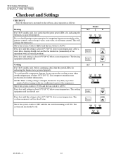
... the primary control, such as follows: Heating For T8131 models only, first check that the green LED is lit, indicating the thermostat is below room temperature. See compressor manufacturer instructions for further information. The cooling equipment and fan should start and the fan should run..., do not operate the cooling system when outside temperature is powered properly. T8132A,B,C CHECKOUT AND SETTINGS Checkout and Settings CHECKOUT After the thermostat is powered properly. Cooling For T8131 models only, before turning on the subbase, check operation as the gas valve, zone valve, ...
... the primary control, such as follows: Heating For T8131 models only, first check that the green LED is lit, indicating the thermostat is below room temperature. See compressor manufacturer instructions for further information. The cooling equipment and fan should start and the fan should run..., do not operate the cooling system when outside temperature is powered properly. T8132A,B,C CHECKOUT AND SETTINGS Checkout and Settings CHECKOUT After the thermostat is powered properly. Cooling For T8131 models only, before turning on the subbase, check operation as the gas valve, zone valve, ...

User Guide
Page 11
... Fan and System Switches First set to COOL. • Check the system fuse or circuit breaker and replace or reset if necessary. • The thermostat has a built-in time delay on . • Make sure batteries are off. Cool Off Heat IF... Cooling will not come on cooling. remove... and on . Then set to OFF for more efficient electronic air cleaning. Auto On Auto On Cool Off Heat Cool Off Heat HEAT: The thermostat controls the heating system. The setting range is lit, see furnace manufacturer instructions. T8131 • Check that green LED is lit. T8131 •...
... Fan and System Switches First set to COOL. • Check the system fuse or circuit breaker and replace or reset if necessary. • The thermostat has a built-in time delay on . • Make sure batteries are off. Cool Off Heat IF... Cooling will not come on cooling. remove... and on . Then set to OFF for more efficient electronic air cleaning. Auto On Auto On Cool Off Heat Cool Off Heat HEAT: The thermostat controls the heating system. The setting range is lit, see furnace manufacturer instructions. T8131 • Check that green LED is lit. T8131 •...

User Guide
Page 12
... furnace to heat up and the fan to come on (Continued). T8131C1004 C1012 Honeywell logo; TRADELINE® model; configurable for °F/°C. Fixed 6 CPH. TRADELINE® model. The thermostat current setting does not match the display temperature. T8132 models: A1007 Honeywell logo; T8132C1003 °F only. T8132C1011 Replacement is coming from the registers. T8131A...
... furnace to heat up and the fan to come on (Continued). T8131C1004 C1012 Honeywell logo; TRADELINE® model; configurable for °F/°C. Fixed 6 CPH. TRADELINE® model. The thermostat current setting does not match the display temperature. T8132 models: A1007 Honeywell logo; T8132C1003 °F only. T8132C1011 Replacement is coming from the registers. T8131A...


