

User Manual
Page 1
METROLOGIC INSTRUMENTS, INC. MS9535 VoyagerBT ® Series Single-Line Hand Held Laser Scanner Installation and User's Guide
METROLOGIC INSTRUMENTS, INC. MS9535 VoyagerBT ® Series Single-Line Hand Held Laser Scanner Installation and User's Guide

User Manual
Page 3
...USB (Powered by the Host Device 14 Establishing Bluetooth Communication Between the Scanner and the Cradle 15 Dynamic Pair Function 15 When the MS9535 Acts as a Client to Other Bluetooth Devices 16 When the MS9535 Acts as a Server to Other Bluetooth Devices 17 The MI9535-5xx Receiver... / Charger Cradle Charging Guidelines and Low Battery Indicators 18 Safety Precautions for Lithium Batteries 19 Communication Protocols 20 Scanner Operation Modes of Opteration 21 Auto-...
...USB (Powered by the Host Device 14 Establishing Bluetooth Communication Between the Scanner and the Cradle 15 Dynamic Pair Function 15 When the MS9535 Acts as a Client to Other Bluetooth Devices 16 When the MS9535 Acts as a Server to Other Bluetooth Devices 17 The MI9535-5xx Receiver... / Charger Cradle Charging Guidelines and Low Battery Indicators 18 Safety Precautions for Lithium Batteries 19 Communication Protocols 20 Scanner Operation Modes of Opteration 21 Auto-...

User Manual
Page 5
... to the host. When resting in hand with the cradle by depressing the CodeGate button for the scanner. For power saving, the scanner can remain powered for added convenience. INTRODUCTION MS9535 VoyagerBT® laser bar code scanner is a new member of an automatic trigger and CodeGate, the VoyagerBT has incorporated the latest Bluetooth®...
... to the host. When resting in hand with the cradle by depressing the CodeGate button for the scanner. For power saving, the scanner can remain powered for added convenience. INTRODUCTION MS9535 VoyagerBT® laser bar code scanner is a new member of an automatic trigger and CodeGate, the VoyagerBT has incorporated the latest Bluetooth®...

User Manual
Page 6
Other items may be ordered for Keyboard Emulation Mode or Serial Emulation Mode. INTRODUCTION Scanner and Accessories Part # MS9535-5 or MS9535-5M 70-79004x 00-02544x 70-73524 BASIC KIT Description VoyagerBT Scanner or VoyagerBT Scanner with Memory MS9535 VoyagerBT Wireless Hand Held Laser Scanner Installation and User's Guide* MetroSelect Single-Line Configuration Guide* Wrist Strap Part # MI9535...
Other items may be ordered for Keyboard Emulation Mode or Serial Emulation Mode. INTRODUCTION Scanner and Accessories Part # MS9535-5 or MS9535-5M 70-79004x 00-02544x 70-73524 BASIC KIT Description VoyagerBT Scanner or VoyagerBT Scanner with Memory MS9535 VoyagerBT Wireless Hand Held Laser Scanner Installation and User's Guide* MetroSelect Single-Line Configuration Guide* Wrist Strap Part # MI9535...

User Manual
Page 7
INTRODUCTION Scanner and Accessories OPTIONAL ACCESSORIES Part # Description AC to DC Power Transformer- To order additional items, contact the dealer, distributor or call Metrologic's Customer Service Department ...
INTRODUCTION Scanner and Accessories OPTIONAL ACCESSORIES Part # Description AC to DC Power Transformer- To order additional items, contact the dealer, distributor or call Metrologic's Customer Service Department ...
User Manual
Page 8
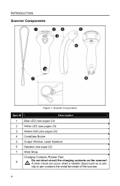
Scanner Components Item # Description 1 Blue LED (see pages 23) 2 White LED (see pages 23) 3 Amber LED (see pages 23) 4 CodeGate Button 5 Output Window, Laser Aperture 6 Speaker (see page 22) 7 Wrist Strap Charging Contacts /Rubber Feet 8 Do not short circuit the charging contacts on the scanner! INTRODUCTION Scanner Components Figure 1. A short circuit can occur when a metallic object such as a coin, clip or pen contacts the metal terminals of the scanner. 4
Scanner Components Item # Description 1 Blue LED (see pages 23) 2 White LED (see pages 23) 3 Amber LED (see pages 23) 4 CodeGate Button 5 Output Window, Laser Aperture 6 Speaker (see page 22) 7 Wrist Strap Charging Contacts /Rubber Feet 8 Do not short circuit the charging contacts on the scanner! INTRODUCTION Scanner Components Figure 1. A short circuit can occur when a metallic object such as a coin, clip or pen contacts the metal terminals of the scanner. 4
User Manual
Page 9
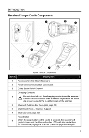
... Address Bar Code (see page 23) Page Button 8 When the page button on the scanner! Scanner Support 7 Blue LED (see page 23) 6 Wall Mount Hook - To discontinue paging the scanner, press the page button again. 5 INTRODUCTION Receiver/Charger Cradle Components Figure 2 Cradle Components Item # Description 1 Recesses for Wall Mount Hardware 2 ...Power and Communication Connectors 3 Cable Strain Relief Channel Charging Contacts 4 Do not short circuit the charging contacts on the cradle is pressed, the scanner will begin to beep and the blue and amber LEDs will alternately flash.
... Address Bar Code (see page 23) Page Button 8 When the page button on the scanner! Scanner Support 7 Blue LED (see page 23) 6 Wall Mount Hook - To discontinue paging the scanner, press the page button again. 5 INTRODUCTION Receiver/Charger Cradle Components Figure 2 Cradle Components Item # Description 1 Recesses for Wall Mount Hardware 2 ...Power and Communication Connectors 3 Cable Strain Relief Channel Charging Contacts 4 Do not short circuit the charging contacts on the cradle is pressed, the scanner will begin to beep and the blue and amber LEDs will alternately flash.

User Manual
Page 10
Figure 3. To maintain compliance with applicable standards, all circuits connected to the scanner must meet applicable performance requirements for SELV (Safety Extra Low Voltage) according to EN/IEC 60950-1. Figure 3 provides examples of manufacture, serial number, safety.... Maintenance Smudges and dirt can interfere with glass cleaner sprayed onto a lint free, no-abrasive cleaning cloth. 6 INTRODUCTION Caution and Serial Number Labels The scanner and cradle have labels that provide important information including; the model number, date of these labels and their locations.
Figure 3. To maintain compliance with applicable standards, all circuits connected to the scanner must meet applicable performance requirements for SELV (Safety Extra Low Voltage) according to EN/IEC 60950-1. Figure 3 provides examples of manufacture, serial number, safety.... Maintenance Smudges and dirt can interfere with glass cleaner sprayed onto a lint free, no-abrasive cleaning cloth. 6 INTRODUCTION Caution and Serial Number Labels The scanner and cradle have labels that provide important information including; the model number, date of these labels and their locations.

User Manual
Page 11
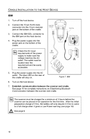
... on the bottom of the host device. 4. CRADLE INSTALLATION TO THE HOST DEVICE RS232 and Light Pen 1. Turn on Establishing Bluetooth Communication between the scanner and cradle. See page 6. 7 Turn off the host device. 2. RS232 and Light Pen 6. Connect the 10-pin RJ45 male connector into the... modular jack on . The outlet must be easily accessible. 5. The blue LED on the rear of the cradle. 3. Establish communication between the scanner and cradle. After the initial preparation charge of 3 hrs, the battery will stay on the bottom of the cradle will only require 2.5 hrs ...
... on the bottom of the host device. 4. CRADLE INSTALLATION TO THE HOST DEVICE RS232 and Light Pen 1. Turn on Establishing Bluetooth Communication between the scanner and cradle. See page 6. 7 Turn off the host device. 2. RS232 and Light Pen 6. Connect the 10-pin RJ45 male connector into the... modular jack on . The outlet must be easily accessible. 5. The blue LED on the rear of the cradle. 3. Establish communication between the scanner and cradle. After the initial preparation charge of 3 hrs, the battery will stay on the bottom of the cradle will only require 2.5 hrs ...

User Manual
Page 12
...charge when it gives a Low Power warning (see page 18). The blue LED on the rear of the cradle. 3. Establish communication between the scanner and cradle. Connect the "Y" ends of the cradle. See page 15 for the first time. See page 6. 8 CRADLE INSTALLATION TO THE ...10-pin RJ45 male connector into the AC outlet. After the initial preparation charge of 3 hours before the scanner can be easily accessible. Disconnect the keyboard from host. 4. The scanner must be located near the requirement and be placed in full operation for complete instructions on . 7. Figure...
...charge when it gives a Low Power warning (see page 18). The blue LED on the rear of the cradle. 3. Establish communication between the scanner and cradle. Connect the "Y" ends of the cradle. See page 15 for the first time. See page 6. 8 CRADLE INSTALLATION TO THE ...10-pin RJ45 male connector into the AC outlet. After the initial preparation charge of 3 hours before the scanner can be easily accessible. Disconnect the keyboard from host. 4. The scanner must be located near the requirement and be placed in full operation for complete instructions on . 7. Figure...

User Manual
Page 13
...complete instructions on the bottom of the cradle. Plug the power supply into the 10-pin modular jack on Establishing Bluetooth Communication between the scanner and cradle. Plug the external power supply into the power jack on . See page 15 for the first time. After the initial ...preparation charge of 3 hrs, the battery will stay on the bottom of the cradle. 3. Establish communication between the scanner and cradle. The outlet must be charged for a minimum of the cradle will only require 2.5 hrs to come to make sure the voltage ...
...complete instructions on the bottom of the cradle. Plug the power supply into the 10-pin modular jack on Establishing Bluetooth Communication between the scanner and cradle. Plug the external power supply into the power jack on . See page 15 for the first time. After the initial ...preparation charge of 3 hrs, the battery will stay on the bottom of the cradle. 3. Establish communication between the scanner and cradle. The outlet must be charged for a minimum of the cradle will only require 2.5 hrs to come to make sure the voltage ...
User Manual
Page 14
... to come to a full charge when it gives a Low Power warning (see page 18). After the initial preparation charge of 3 hours before the scanner can be easily accessible. 5. The outlet must be charged for a minimum of 3 hrs, the battery will stay on Establishing Bluetooth Communication between the... connector into the power jack on the bottom of the power supply to the IBM port on the host device. 7. Establish communication between the scanner and cradle. Connect the IBM SDL connector to make sure the voltage matches the AC outlet. Figure 7. See page 6. 10 Plug the power...
... to come to a full charge when it gives a Low Power warning (see page 18). After the initial preparation charge of 3 hours before the scanner can be easily accessible. 5. The outlet must be charged for a minimum of 3 hrs, the battery will stay on Establishing Bluetooth Communication between the... connector into the power jack on the bottom of the power supply to the IBM port on the host device. 7. Establish communication between the scanner and cradle. Connect the IBM SDL connector to make sure the voltage matches the AC outlet. Figure 7. See page 6. 10 Plug the power...
User Manual
Page 15
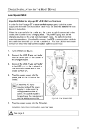
... in the cradle and the power supply is connected to the cradle, the scanner is critical to connect the USB communication cable to the cradle and the USB port on the host device. The blue LED on the rear ... 8. Low Speed USB 5. Installation instructions continued on the host device. CRADLE INSTALLATION TO THE HOST DEVICE Low Speed USB Important Notes for VoyagerBT USB Interface Scanners In order for the VoyagerBT to scan and charge properly both the power supply and the USB communication cable must be located near the requirement...
... in the cradle and the power supply is connected to the cradle, the scanner is critical to connect the USB communication cable to the cradle and the USB port on the host device. The blue LED on the rear ... 8. Low Speed USB 5. Installation instructions continued on the host device. CRADLE INSTALLATION TO THE HOST DEVICE Low Speed USB Important Notes for VoyagerBT USB Interface Scanners In order for the VoyagerBT to scan and charge properly both the power supply and the USB communication cable must be located near the requirement...

User Manual
Page 16
CRADLE INSTALLATION TO THE HOST DEVICE Low Speed USB 6. Establish communication between the scanner and cradle. See page 15 for the first time. Turn on Establishing Bluetooth Communication between the scanner and cradle. As a default, the MI9535-538 leaves the factory with USB Keyboard Emulation Mode enabled. Scan...code to a full charge when it gives a Low Power warning (see page 18). 12 After the initial preparation charge of 3 hours before the scanner can be charged for a minimum of 3 hrs, the battery will only require 2.5 hrs to come to configure the MI9535-538 for USB Serial...
CRADLE INSTALLATION TO THE HOST DEVICE Low Speed USB 6. Establish communication between the scanner and cradle. See page 15 for the first time. Turn on Establishing Bluetooth Communication between the scanner and cradle. As a default, the MI9535-538 leaves the factory with USB Keyboard Emulation Mode enabled. Scan...code to a full charge when it gives a Low Power warning (see page 18). 12 After the initial preparation charge of 3 hours before the scanner can be charged for a minimum of 3 hrs, the battery will only require 2.5 hrs to come to configure the MI9535-538 for USB Serial...

User Manual
Page 17
... cradle. Turn on the bottom of the cradle will only require 2.5 hrs to come to make sure the voltage matches the AC outlet. The scanner must be located near the requirement and be placed in full operation for the first time. Plug the power supply into the power jack on...device. 7. See page 15 for a minimum of 3 hrs, the battery will stay on the host device. 4. After the initial preparation charge of 3 hours before the scanner can be easily accessible. Turn off the host device. 2. Connect the 10-pin RJ45 male connector into the AC outlet. Check the AC input requirements...
... cradle. Turn on the bottom of the cradle will only require 2.5 hrs to come to make sure the voltage matches the AC outlet. The scanner must be located near the requirement and be placed in full operation for the first time. Plug the power supply into the power jack on...device. 7. See page 15 for a minimum of 3 hrs, the battery will stay on the host device. 4. After the initial preparation charge of 3 hours before the scanner can be easily accessible. Turn off the host device. 2. Connect the 10-pin RJ45 male connector into the AC outlet. Check the AC input requirements...

User Manual
Page 18
...Type A plus power connector to a full charge when it gives a Low Power warning (see page 18). Establish communication between the scanner and cradle. Full Speed USB The scanner must be charged for a minimum of 3 hrs, the battery will only require 2.5 hrs to come to the USB port on ... bottom of the charger cradle. 3. After the initial preparation charge of 3 hours before the scanner can be placed in full operation for complete instructions on Establishing Bluetooth Communication between the scanner and cradle. Connect the 10-pin RJ45 male connector into the 10-pin modular jack on ...
...Type A plus power connector to a full charge when it gives a Low Power warning (see page 18). Establish communication between the scanner and cradle. Full Speed USB The scanner must be charged for a minimum of 3 hrs, the battery will only require 2.5 hrs to come to the USB port on ... bottom of the charger cradle. 3. After the initial preparation charge of 3 hours before the scanner can be placed in full operation for complete instructions on Establishing Bluetooth Communication between the scanner and cradle. Connect the 10-pin RJ45 male connector into the 10-pin modular jack on ...

User Manual
Page 19
...to existing links. 15 Place scanner #2 into sleep mode by scanning that the MS9535 will only communicate with a cradle whose Bluetooth address was the last address scanned. The link between the scanner and cradle: 1. Scanner #1 has now re-established a communication link with scanner #1. The unique address code...scan a cradle's bluetooth code when it is paired with the MS9535, another scanner can be paired with that cradle until the original connection is broken. Any attempt to an active scanner, not in the scanner razzing to indicate a communication link is not possible due to note...
...to existing links. 15 Place scanner #2 into sleep mode by scanning that the MS9535 will only communicate with a cradle whose Bluetooth address was the last address scanned. The link between the scanner and cradle: 1. Scanner #1 has now re-established a communication link with scanner #1. The unique address code...scan a cradle's bluetooth code when it is paired with the MS9535, another scanner can be paired with that cradle until the original connection is broken. Any attempt to an active scanner, not in the scanner razzing to indicate a communication link is not possible due to note...

User Manual
Page 20
... will act as a complete system. The devices' Bluetooth address must be scanned to another Bluetooth device. ESTABLISHING BLUETOOTH COMMUNICATION When the MS9535 Acts as a Client to Other Bluetooth Devices The MS9535 scanner can also link to establish the communication. ³ 0 0 0CA7 FFFF 9 9 Example Bluetooth Address with FNC3 b) If the Bluetooth address is NOT...
... will act as a complete system. The devices' Bluetooth address must be scanned to another Bluetooth device. ESTABLISHING BLUETOOTH COMMUNICATION When the MS9535 Acts as a Client to Other Bluetooth Devices The MS9535 scanner can also link to establish the communication. ³ 0 0 0CA7 FFFF 9 9 Example Bluetooth Address with FNC3 b) If the Bluetooth address is NOT...

User Manual
Page 21
This will allow other Bluetooth devices 17 ESTABLISHING BLUETOOTH COMMUNICATION When the MS9535 Acts as a Server to Other Bluetooth Devices Scan the Provide Service bar code below to enable the MS9535 to the scanner and attempt communication. Use this bar code to establish communication directly with a Bluetooth enabled device, bypassing the cradle. ³ 0 0 0CA7 0 0 0 0 0 0 Provide service to other Bluetooth devices to send inquiries to act as a server and be detected by another Bluetooth device.
This will allow other Bluetooth devices 17 ESTABLISHING BLUETOOTH COMMUNICATION When the MS9535 Acts as a Server to Other Bluetooth Devices Scan the Provide Service bar code below to enable the MS9535 to the scanner and attempt communication. Use this bar code to establish communication directly with a Bluetooth enabled device, bypassing the cradle. ³ 0 0 0CA7 0 0 0 0 0 0 Provide service to other Bluetooth devices to send inquiries to act as a server and be detected by another Bluetooth device.

User Manual
Page 22
...to complete the initial 3 hour charge. z The laser is not activated when a bar code is recommended that the amber LED on and the scanner has automatically entered normal sleep mode to reserve power. z The CodeGate button is pressed, the laser comes on briefly but does not stay on the... the cradle be placed into full sleep mode. THE MI9535-5XX RECEIVER / CHARGER CRADLE Charging Guidelines and Low Battery Indicators The scanner should be fully charged prior to being placed into the cradle. Metrologic recommends that the unit be established first before charging. z The ...
...to complete the initial 3 hour charge. z The laser is not activated when a bar code is recommended that the amber LED on and the scanner has automatically entered normal sleep mode to reserve power. z The CodeGate button is pressed, the laser comes on briefly but does not stay on the... the cradle be placed into full sleep mode. THE MI9535-5XX RECEIVER / CHARGER CRADLE Charging Guidelines and Low Battery Indicators The scanner should be fully charged prior to being placed into the cradle. Metrologic recommends that the unit be established first before charging. z The ...


