User Manual
Page 5
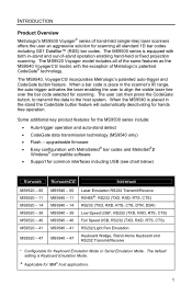
... for hands free operation. upgradeable firmware • Easy configuration with the exception of Metrologic's patented CodeGate® technology. The default setting is placed in the scanner's IR range, the auto-trigger activates the laser enabling the user to the host system. Some additional key product features for IBM® host applications. 1 The user can then press the CodeGate button, to transmit the data to align the visible laser line over the bar code selected for Keyboard Emulation Mode or Serial Emulation Mode. The...
... for hands free operation. upgradeable firmware • Easy configuration with the exception of Metrologic's patented CodeGate® technology. The default setting is placed in the scanner's IR range, the auto-trigger activates the laser enabling the user to the host system. Some additional key product features for IBM® host applications. 1 The user can then press the CodeGate button, to transmit the data to align the visible laser line over the bar code selected for Keyboard Emulation Mode or Serial Emulation Mode. The...

User Manual
Page 6
... Relief 59-59000x-3 RS232 PowerLink Cable with Built in Power Jack Black, Straight cord, with Short Strain Relief 53-53002x-3 Keyboard Wedge PowerLink Cable with Adapter Cable Black, Coiled cord, with Long Strain Relief 53-53020x-3 Stand Alone Keyboard Wedge PowerLink Cable Black, Coiled cord, with CodeGate MetroSelect Single-Line Configuration Guide* 00-02410 MS9500 Voyager Series Single-Line Hand Held Laser Scanner Installation and User's Guide* * Available for the specific protocol being used.
... Relief 59-59000x-3 RS232 PowerLink Cable with Built in Power Jack Black, Straight cord, with Short Strain Relief 53-53002x-3 Keyboard Wedge PowerLink Cable with Adapter Cable Black, Coiled cord, with Long Strain Relief 53-53020x-3 Stand Alone Keyboard Wedge PowerLink Cable Black, Coiled cord, with CodeGate MetroSelect Single-Line Configuration Guide* 00-02410 MS9500 Voyager Series Single-Line Hand Held Laser Scanner Installation and User's Guide* * Available for the specific protocol being used.

User Manual
Page 11
..., Laser Emulation, and Light Pen Emulation 1. Please refer to the MetroSelect Single-Line Configuration Guide or MetroSet2's help files for information on the scanner. If you recall defaults while re-configuring your scanner the Laser Emulation Mode will be communicated properly to step #5. 3. Connect the power supply into the jack on enabling the Laser Emulation Mode. Plugging the scanner into the power jack on the host system. The outlet should be enabled. Refer to the proper port on the PowerLink cable. 4. If...
..., Laser Emulation, and Light Pen Emulation 1. Please refer to the MetroSelect Single-Line Configuration Guide or MetroSet2's help files for information on the scanner. If you recall defaults while re-configuring your scanner the Laser Emulation Mode will be communicated properly to step #5. 3. Connect the power supply into the jack on enabling the Laser Emulation Mode. Plugging the scanner into the power jack on the host system. The outlet should be enabled. Refer to the proper port on the PowerLink cable. 4. If...
User Manual
Page 12
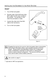
... MVC cable to the MetroSelect Single-Line Configuration Guide or MetroSet2's help files for IBM® host applications. 8 You will be communicated properly to the host system. Figure 7. INSTALLING THE SCANNER TO THE HOST SYSTEM RS485” 1. Connect the other end of the MVC cable into a port on the scanner. Please refer to the host device. 4. Turn off the host system. 2. Plugging the scanner into the 10-pin socket on the host system does not guarantee that scanned...
... MVC cable to the MetroSelect Single-Line Configuration Guide or MetroSet2's help files for IBM® host applications. 8 You will be communicated properly to the host system. Figure 7. INSTALLING THE SCANNER TO THE HOST SYSTEM RS485” 1. Connect the other end of the MVC cable into a port on the scanner. Please refer to the host device. 4. Turn off the host system. 2. Plugging the scanner into the 10-pin socket on the host system does not guarantee that scanned...

User Manual
Page 13
... 8. Connect the 10-pin RJ45 male connector into an AC outlet. Power up the host system. Contact a Metrologic Customer Service Representative if you require an external power supply. Connect the power supply into the jack on changing the scanner's factory default configuration. Connect the PowerLink cable to the MetroSelect Single-Line Configuration Guide or MetroSet2's help files for instructions on the scanner. Please refer to the keyboard and the PC's keyboard port. Turn off the host system. 2. If necessary use the...
... 8. Connect the 10-pin RJ45 male connector into an AC outlet. Power up the host system. Contact a Metrologic Customer Service Representative if you require an external power supply. Connect the power supply into the jack on changing the scanner's factory default configuration. Connect the PowerLink cable to the MetroSelect Single-Line Configuration Guide or MetroSet2's help files for instructions on the scanner. Please refer to the keyboard and the PC's keyboard port. Turn off the host system. 2. If necessary use the...

User Manual
Page 14
.... 5. Turn on the scanner. Verify the AC input requirements of the scanner or the computer. Turn off the host system. 2. Connect the 10-pin RJ45 male connector into an AC outlet. The outlet should be communicated properly to the MetroSelect Single-Line Configuration Guide or MetroSet2's help files for instructions on the host system does not guarantee that scanned information will hear a 'click' when the connection is receiving power...
.... 5. Turn on the scanner. Verify the AC input requirements of the scanner or the computer. Turn off the host system. 2. Connect the 10-pin RJ45 male connector into an AC outlet. The outlet should be communicated properly to the MetroSelect Single-Line Configuration Guide or MetroSet2's help files for instructions on the host system does not guarantee that scanned information will hear a 'click' when the connection is receiving power...
User Manual
Page 15
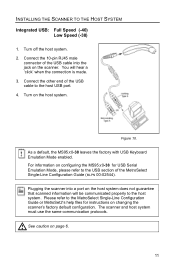
Connect the 10-pin RJ45 male connector of the MetroSelect Single-Line Configuration Guide (MLPN 00-02544). You will be communicated properly to the MetroSelect Single-Line Configuration Guide or MetroSet2's help files for USB Serial Emulation Mode, please refer to the host USB port. 4. Please refer to the host system. See caution on the host system. Turn off the host system. 2. Turn on page 6. 11 As a default, the MS95x0-38 leaves the factory with USB Keyboard Emulation Mode enabled. For information on the host system does...
Connect the 10-pin RJ45 male connector of the MetroSelect Single-Line Configuration Guide (MLPN 00-02544). You will be communicated properly to the MetroSelect Single-Line Configuration Guide or MetroSet2's help files for USB Serial Emulation Mode, please refer to the host USB port. 4. Please refer to the host system. See caution on the host system. Turn off the host system. 2. Turn on page 6. 11 As a default, the MS95x0-38 leaves the factory with USB Keyboard Emulation Mode enabled. For information on the host system does...

User Manual
Page 16
...; Auto-triggers while in the stand • Bar code is automatically decoded and transmitted CodeGate, Out-of-Stand • CodeGate activates when removed from the stand • Bar code data is transmitted when the button is pressed Manual Activation Mode*, Out-of-Stand • Button activates laser • Bar code data is scanned and transmitted while button is not a default setting. THE MS9540 VOYAGERCG® SERIES How to the MetroSelect Configuration Guide for instructions on enabling the Manual Activation Mode. Refer to Use CodeGate...
...; Auto-triggers while in the stand • Bar code is automatically decoded and transmitted CodeGate, Out-of-Stand • CodeGate activates when removed from the stand • Bar code data is transmitted when the button is pressed Manual Activation Mode*, Out-of-Stand • Button activates laser • Bar code data is scanned and transmitted while button is not a default setting. THE MS9540 VOYAGERCG® SERIES How to the MetroSelect Configuration Guide for instructions on enabling the Manual Activation Mode. Refer to Use CodeGate...
User Manual
Page 21
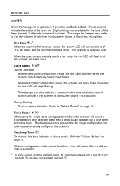
... beeps three times. During Start-up This is ready to "Failure Modes" on , the red* LED will flash, and the scanner will beep once. Refer to the MetroSelect Single-Line Configuration Guide or MetroSet2's help files. The scanner is a failure indicator. INDICATORS Audible When the Voyager is in configuration mode, a short razzberry tone will sound if an invalid bar code is scanned. * In some custom units the standard green LED has been replaced with a blue LED and the red LED...
... beeps three times. During Start-up This is ready to "Failure Modes" on , the red* LED will flash, and the scanner will beep once. Refer to the MetroSelect Single-Line Configuration Guide or MetroSet2's help files. The scanner is a failure indicator. INDICATORS Audible When the Voyager is in configuration mode, a short razzberry tone will sound if an invalid bar code is scanned. * In some custom units the standard green LED has been replaced with a blue LED and the red LED...
User Manual
Page 22
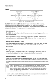
... read (default mode only). LED Configuration The MS9540 has three LED indicators located on . The MS9520 has two LED indicators located on the head of the scanner and the current scan. The bar code will remain illuminated until the data can be illuminated if the scanner is ready to the host device. The green* LED will be received. After a successful scan, the scanner transmits the data to be decoded and transmitted to the scanner...
... read (default mode only). LED Configuration The MS9540 has three LED indicators located on . The MS9520 has two LED indicators located on the head of the scanner and the current scan. The bar code will remain illuminated until the data can be illuminated if the scanner is ready to the host device. The green* LED will be received. After a successful scan, the scanner transmits the data to be decoded and transmitted to the scanner...

User Manual
Page 25
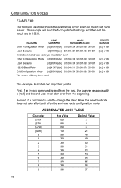
To enter serial configuration mode, send the following example will set the scanner to the factory default settings, Disable Scanning of Code 128 bar codes, change will send a [nak] and you must start over. 6. To exit serial configuration mode, send the following command [stx]999999[etx], the scanner will beep three times! THE '3' SHOULD NOT BE SENT. As you would normally scan the bar codes. 21 During configuration, the motor and laser turn off. If a command is sent to the scanner to be scanned (such as a configurable prefix. Prefix #1 [stx]903500...
To enter serial configuration mode, send the following example will set the scanner to the factory default settings, Disable Scanning of Code 128 bar codes, change will send a [nak] and you must start over. 6. To exit serial configuration mode, send the following command [stx]999999[etx], the scanner will beep three times! THE '3' SHOULD NOT BE SENT. As you would normally scan the bar codes. 21 During configuration, the motor and laser turn off. If a command is sent to the scanner to be scanned (such as a configurable prefix. Prefix #1 [stx]903500...
User Manual
Page 26
... load the factory default settings and then set the baud rate to change the Baud Rate, the new baud rate does not take effect until after the end-user exits configuration mode. SCANNER RESPONSE [ack] or 06h [nak] or 15h [ack] or 06h [ack] or 06h [ack] or 06h [ack] or 06h This example illustrates two important points. Second, if a command is sent from the host, the scanner responds with...
... load the factory default settings and then set the baud rate to change the Baud Rate, the new baud rate does not take effect until after the end-user exits configuration mode. SCANNER RESPONSE [ack] or 06h [nak] or 15h [ack] or 06h [ack] or 06h [ack] or 06h [ack] or 06h This example illustrates two important points. Second, if a command is sent from the host, the scanner responds with...

User Manual
Page 27
... customer by Metrologic. 9. If using USB or RS232 for IBM® host applications 23 Plug the scanner into a serial communication port on the Configure Scanner button. 6. Choose the Voyager/9520 N/R or Voyager/9540 N/R from http://www.metrologic.com/corporate/download. ” Applicable for the upgrade process, the standard USB or RS232 cable provided with flash upgradeable firmware. Click on the host system. 2. Locate and open the flash upgrade file supplied by a customer service representative and Metrologic's MetroSet2 software . A message...
... customer by Metrologic. 9. If using USB or RS232 for IBM® host applications 23 Plug the scanner into a serial communication port on the Configure Scanner button. 6. Choose the Voyager/9520 N/R or Voyager/9540 N/R from http://www.metrologic.com/corporate/download. ” Applicable for the upgrade process, the standard USB or RS232 cable provided with flash upgradeable firmware. Click on the host system. 2. Locate and open the flash upgrade file supplied by a customer service representative and Metrologic's MetroSet2 software . A message...

User Manual
Page 31
... is required. Some host systems cannot supply enough current to the unit. A flash ROM upgrade is a VLD failure. Verify that is for a longer time. Enable beeper and select a tone. UPC/EAN, Code 39, interleaved 2 of bar code being supplied to power Voyager. TROUBLESHOOTING GUIDE The following guide is not enabled. The unit is trying to scan a particular symbology that the type of 5, Code 93, Code 128 and Codabar are enabled by default.
... is required. Some host systems cannot supply enough current to the unit. A flash ROM upgrade is a VLD failure. Verify that is for a longer time. Enable beeper and select a tone. UPC/EAN, Code 39, interleaved 2 of bar code being supplied to power Voyager. TROUBLESHOOTING GUIDE The following guide is not enabled. The unit is trying to scan a particular symbology that the type of 5, Code 93, Code 128 and Codabar are enabled by default.

User Manual
Page 32
... replaced with the bar code. The scanner defaults to support ACK/NAK, RTS/CTS, XON/XOFF or D/E, verify that the host cable and host are supporting the handshaking properly. Check if the correct minimum symbol length is no data. The unit scans, but the data transmitted to the proper host port. The unit scans the bar code but there is set. Make sure that required by using the MetroSelect Single-Line Configuration Guide. * In some inter-character delay to be configured for character length lock or minimum length. The bar code...
... replaced with the bar code. The scanner defaults to support ACK/NAK, RTS/CTS, XON/XOFF or D/E, verify that the host cable and host are supporting the handshaking properly. Check if the correct minimum symbol length is no data. The unit scans, but the data transmitted to the proper host port. The unit scans the bar code but there is set. Make sure that required by using the MetroSelect Single-Line Configuration Guide. * In some inter-character delay to be configured for character length lock or minimum length. The bar code...

User Manual
Page 33
... the baud rate and parity of characters. Check to the correct com port on the host device. 29 The unit will power-up and scan but the data is not correct. The cable is connected to make sure that the program is operating in both settings. The unit will power-up table. The unit's configuration is not correct. TROUBLESHOOTING GUIDE Symptoms Possible Causes Solution The following item is not working or not configured...
... the baud rate and parity of characters. Check to the correct com port on the host device. 29 The unit will power-up and scan but the data is not correct. The cable is connected to make sure that the program is operating in both settings. The unit will power-up table. The unit's configuration is not correct. TROUBLESHOOTING GUIDE Symptoms Possible Causes Solution The following item is not working or not configured...
User Manual
Page 34
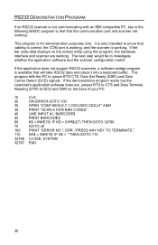
... an IBM compatible PC, key in the following BASIC program to test that the communication port and scanner are working. If the bar code data displays on the back of your PC. 10 20 30 35 40 50 60 70 100 110 32766 32767 CLS ON ERROR GOTO 100 OPEN "COM1:9600,S,7,1,CSO,DSO,CD0,LF" AS#1 PRINT "SCAN A FEW BAR CODES" LINE INPUT #1, BARCODE$ PRINT BARCODE...
... an IBM compatible PC, key in the following BASIC program to test that the communication port and scanner are working. If the bar code data displays on the back of your PC. 10 20 30 35 40 50 60 70 100 110 32766 32767 CLS ON ERROR GOTO 100 OPEN "COM1:9600,S,7,1,CSO,DSO,CD0,LF" AS#1 PRINT "SCAN A FEW BAR CODES" LINE INPUT #1, BARCODE$ PRINT BARCODE...

User Manual
Page 35
... a Metrologic service representative System Interfaces: RS232, PC Keyboard Wedge, Stand-Alone Keyboard, RS485 IBM 468X/469X, Light Pen Emulation, Laser Emulation, RS232 with a white LED. Specifications are subject to scan Visual Indicators: Default Settings Red* LED Yellow LED (MS9540 Only) good read ON, CodeGate button is inactive OFF, CodeGate button is active * In some custom units, the standard green LED has been replaced with a blue LED and the red LED has been replaced with DSR, Low Speed USB (Serial Emulation or Keyboard Emulation), Full...
... a Metrologic service representative System Interfaces: RS232, PC Keyboard Wedge, Stand-Alone Keyboard, RS485 IBM 468X/469X, Light Pen Emulation, Laser Emulation, RS232 with a white LED. Specifications are subject to scan Visual Indicators: Default Settings Red* LED Yellow LED (MS9540 Only) good read ON, CodeGate button is inactive OFF, CodeGate button is active * In some custom units, the standard green LED has been replaced with a blue LED and the red LED has been replaced with DSR, Low Speed USB (Serial Emulation or Keyboard Emulation), Full...

User Manual
Page 38
DEFAULT SETTINGS Parameter Mod 43 Check on Code 39 MSI-Plessy 10/10 Check Digit MSI-Plessy Mod 10 Check Digit Paraf Support ITF Default RS232 Light Pen RS485 KBW USB Laser Emulation * ITF Symbol Lengths Variable Minimum Symbol Length 3 Symbol Length Lock None Bars High as Code 39 * Spaces High as Code 39 Bars High as Scanned Spaces High as Scanned DTS/SIEMENS DTS/NIXDORF * NCR F NCR S Poll light pen source Beeper tone Beep Transmit Sequence Communication Timeout Normal Before transmit None Razzberry Tone...
DEFAULT SETTINGS Parameter Mod 43 Check on Code 39 MSI-Plessy 10/10 Check Digit MSI-Plessy Mod 10 Check Digit Paraf Support ITF Default RS232 Light Pen RS485 KBW USB Laser Emulation * ITF Symbol Lengths Variable Minimum Symbol Length 3 Symbol Length Lock None Bars High as Code 39 * Spaces High as Code 39 Bars High as Scanned Spaces High as Scanned DTS/SIEMENS DTS/NIXDORF * NCR F NCR S Poll light pen source Beeper tone Beep Transmit Sequence Communication Timeout Normal Before transmit None Razzberry Tone...

User Manual
Page 39
...msecs Default RS232 Light Pen RS485 KBW USB Laser Emulation Same symbol rescan timeout: 875 msecs * Same symbol rescan timeout: 1000 msecs No Same symbol timeout Infinite Same symbol timeout Inter-character delay 1 msecs Configurable in 1 msec steps 10 msecs (max 255 msecs) in KBW Number of scan buffers (maximum) 4 Transmit UPC-A check digit * Transmit UPC-E check digit Expand UPC-E Convert UPC-A to EAN-13 Transmit lead zero on UPC-E Transmit UPC-A number system * Transmit UPC-A Manufacturer ID# * Transmit UPC -A Item ID# * Transmit Codabar Start/Stop Characters...
...msecs Default RS232 Light Pen RS485 KBW USB Laser Emulation Same symbol rescan timeout: 875 msecs * Same symbol rescan timeout: 1000 msecs No Same symbol timeout Infinite Same symbol timeout Inter-character delay 1 msecs Configurable in 1 msec steps 10 msecs (max 255 msecs) in KBW Number of scan buffers (maximum) 4 Transmit UPC-A check digit * Transmit UPC-E check digit Expand UPC-E Convert UPC-A to EAN-13 Transmit lead zero on UPC-E Transmit UPC-A number system * Transmit UPC-A Manufacturer ID# * Transmit UPC -A Item ID# * Transmit Codabar Start/Stop Characters...


