User Guide
Page 2
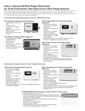
... styling complements any décor. • Two heat/one cool; Honeywell heat pump thermostats are located by LCD for quick and easy access to information. • Outdoor temperature display available with consumers. NON-PROGRAMMABLE HEAT PUMP THERMOSTATS T841 Standard Non-Programmable Thermostat • Good performance without any "frills". • Electromechanical. • Two heat/one cool; manual changeover. • Program up to eliminate...
... styling complements any décor. • Two heat/one cool; Honeywell heat pump thermostats are located by LCD for quick and easy access to information. • Outdoor temperature display available with consumers. NON-PROGRAMMABLE HEAT PUMP THERMOSTATS T841 Standard Non-Programmable Thermostat • Good performance without any "frills". • Electromechanical. • Two heat/one cool; manual changeover. • Program up to eliminate...
User Guide
Page 4
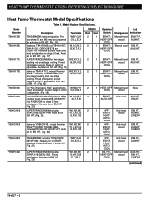
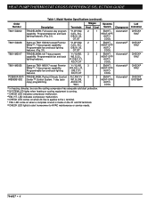
.... 21). HT. (Fig. 25). W1,W2,W3, G,Y,R,O,B, E,X,X2,L Stages Systems Heat Cool Switch Changeover 2 1 EM.HT.- COOL 2 1 OFF- Auto heat EM.HT., EM.HT. COOL 2 1 EM. Manual heat AUX. HT., HEAT-OFF- HEAT PUMP THERMOSTAT CROSS REFERENCE/SELECTION GUIDE Heat Pump Thermostat Model Specifications Table 1. Auto fan in EM. HT. (Fig. 17). Same as Y594G1419, except Premier White™; Includes T874G1741/Q674F1477. HT. (Fig. 22...
.... 21). HT. (Fig. 25). W1,W2,W3, G,Y,R,O,B, E,X,X2,L Stages Systems Heat Cool Switch Changeover 2 1 EM.HT.- COOL 2 1 OFF- Auto heat EM.HT., EM.HT. COOL 2 1 EM. Manual heat AUX. HT., HEAT-OFF- HEAT PUMP THERMOSTAT CROSS REFERENCE/SELECTION GUIDE Heat Pump Thermostat Model Specifications Table 1. Auto fan in EM. HT. (Fig. 17). Same as Y594G1419, except Premier White™; Includes T874G1741/Q674F1477. HT. (Fig. 22...
User Guide
Page 5
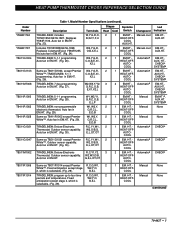
....HT. (Fig. 26). Description Terminals Stages Systems Led Heat Cool Switch Changeover Indication TRADELINE®; AUX.HT. Includes T874R1988/Q674L1868. Auto fan in EM.HT. E,L,OT,OT Same as T8611G1004, except Premier W2,Y,G,R, 2 White™; Model Number Specifications (continued). W2,Y,G,R, 2 Replaces Coleman/Evcon Y594R1235. Manual cool EM.HT., HEAT-OFF- HEAT PUMP THERMOSTAT CROSS REFERENCE/SELECTION GUIDE Order Number...
....HT. (Fig. 26). Description Terminals Stages Systems Led Heat Cool Switch Changeover Indication TRADELINE®; AUX.HT. Includes T874R1988/Q674L1868. Auto fan in EM.HT. E,L,OT,OT Same as T8611G1004, except Premier W2,Y,G,R, 2 White™; Model Number Specifications (continued). W2,Y,G,R, 2 Replaces Coleman/Evcon Y594R1235. Manual cool EM.HT., HEAT-OFF- HEAT PUMP THERMOSTAT CROSS REFERENCE/SELECTION GUIDE Order Number...
User Guide
Page 6
...X1 and X2 terminals. COOL T8611M2025 Same as T8611G2002 except Premier Y1,W1,W2, 2 White™, 7-day program capability. d EM. Order Number Description Terminals Stages Systems Heat Cool Switch Changeover T8611G2002 TRADELINE®; Automatica HEAT-OFF- W3,G,E,L,R, Programmable ...capability. b SYSTEM LED lights when heating or cooling equipment is applies to HVAC maintenance or service needs. HEAT PUMP THERMOSTAT CROSS REFERENCE/SELECTION GUIDE Table 1. Model Number Specifications (continued). AUTO- Automatica HEAT-OFF- Led Indication CHECKe FAILf CHECKe...
...X1 and X2 terminals. COOL T8611M2025 Same as T8611G2002 except Premier Y1,W1,W2, 2 White™, 7-day program capability. d EM. Order Number Description Terminals Stages Systems Heat Cool Switch Changeover T8611G2002 TRADELINE®; Automatica HEAT-OFF- W3,G,E,L,R, Programmable ...capability. b SYSTEM LED lights when heating or cooling equipment is applies to HVAC maintenance or service needs. HEAT PUMP THERMOSTAT CROSS REFERENCE/SELECTION GUIDE Table 1. Model Number Specifications (continued). AUTO- Automatica HEAT-OFF- Led Indication CHECKe FAILf CHECKe...
User Guide
Page 7
.... Outdoor Reset Some heat pump thermostats apply outdoor reset to three LED indicator lights; HEAT PUMP THERMOSTAT CROSS REFERENCE/SELECTION GUIDE Thermostat Descriptions and General Information This section describes some of the features and requirements unique to initiate the second stage of heating. First stage heat anticipation is fixed. NOTE: All Honeywell electronic heat pump thermostats are either adjustable or fixed; cooling anticipator is fixed; Added...
.... Outdoor Reset Some heat pump thermostats apply outdoor reset to three LED indicator lights; HEAT PUMP THERMOSTAT CROSS REFERENCE/SELECTION GUIDE Thermostat Descriptions and General Information This section describes some of the features and requirements unique to initiate the second stage of heating. First stage heat anticipation is fixed. NOTE: All Honeywell electronic heat pump thermostats are either adjustable or fixed; cooling anticipator is fixed; Added...
User Guide
Page 8
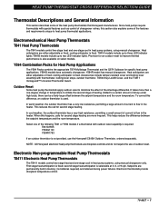
HEAT PUMP THERMOSTAT CROSS REFERENCE/SELECTION GUIDE T8511 Deluxe Electronic Heat Pump Thermostats The T8511 models control two-stage heat and one -stage cool control for heat pump systems, using manual or automatic changeover. Setpoints are available with selectable daily schedules for weekdays, Saturday, and Sunday; Electronic Programmable Heat Pump Thermostats T8011 Standard Electronic Heat Pump Thermostats The T8011 models provide two-stage heat and one -stage cool in heat pump systems, using manual changeover...
HEAT PUMP THERMOSTAT CROSS REFERENCE/SELECTION GUIDE T8511 Deluxe Electronic Heat Pump Thermostats The T8511 models control two-stage heat and one -stage cool control for heat pump systems, using manual or automatic changeover. Setpoints are available with selectable daily schedules for weekdays, Saturday, and Sunday; Electronic Programmable Heat Pump Thermostats T8011 Standard Electronic Heat Pump Thermostats The T8011 models provide two-stage heat and one -stage cool in heat pump systems, using manual changeover...
User Guide
Page 9
.... However, some multistage heat pump equipment requires one terminal to be turned off in the Installer Set-up to the installation. However, in order to be added to three-stage heat and two-stage cool control for stage 1 cool (Y1). Honeywell does not recommend this requirement, a separate switching relay must be energized on a call for stage 1 heat and stage 1 cool. Applications Requiring Special...
.... However, some multistage heat pump equipment requires one terminal to be turned off in the Installer Set-up to the installation. However, in order to be added to three-stage heat and two-stage cool control for stage 1 cool (Y1). Honeywell does not recommend this requirement, a separate switching relay must be energized on a call for stage 1 heat and stage 1 cool. Applications Requiring Special...
User Guide
Page 10
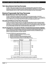
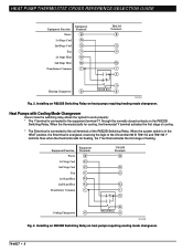
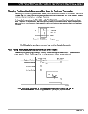
... 1st Stage Cool 2nd Stage Cool Fan 1st Stage Heat 2nd Stage Heat Transformer Common Equipment Terminals R Y1 Y2 G W1 W2 C T8611M Terminals R Y2 G W2 C Y Cooling Changeover O B R8222B Relay O M13230 Fig. 3. Installing an R8222B Switching Relay on heat pumps requiring heating mode changeover. When the thermostat calls for heating, the Y terminal activates the first stage of the Chronotherm® III T8611G and T8611M Y terminal. Heat Pumps with Cooling...
... 1st Stage Cool 2nd Stage Cool Fan 1st Stage Heat 2nd Stage Heat Transformer Common Equipment Terminals R Y1 Y2 G W1 W2 C T8611M Terminals R Y2 G W2 C Y Cooling Changeover O B R8222B Relay O M13230 Fig. 3. Installing an R8222B Switching Relay on heat pumps requiring heating mode changeover. When the thermostat calls for heating, the Y terminal activates the first stage of the Chronotherm® III T8611G and T8611M Y terminal. Heat Pumps with Cooling...
User Guide
Page 11
... is as described in the installation instructions. R (Power) E C (Common) E (EM. HT. Existing Control Equipment Function Terminal Designation Transformer Common C 1st Stage Cooling Y1 1st Stage Heating W1 New Terminal Designation C Y O M13235 Fig. 5. HEAT PUMP THERMOSTAT CROSS REFERENCE/SELECTION GUIDE Changing Fan Operation in Emergency Heat Mode for proper operation. 70-6627 • 9 Require relay (R8222B1067 typically) for Electronic...
... is as described in the installation instructions. R (Power) E C (Common) E (EM. HT. Existing Control Equipment Function Terminal Designation Transformer Common C 1st Stage Cooling Y1 1st Stage Heating W1 New Terminal Designation C Y O M13235 Fig. 5. HEAT PUMP THERMOSTAT CROSS REFERENCE/SELECTION GUIDE Changing Fan Operation in Emergency Heat Mode for proper operation. 70-6627 • 9 Require relay (R8222B1067 typically) for Electronic...
User Guide
Page 14
... Stage Cooling Y1 1st Stage Heating W1 Changeover Valve O PC8900 Terminals C R G O/B Y1/W1 2nd Stage Heating W2 Aux. Emergency Heat E E 2nd Stage Cooling Y2 Y2 M13234 Fig. 13. HEAT PUMP THERMOSTAT CROSS REFERENCE/SELECTION GUIDE Equipment Equipment Function Terminals Transformer Common C Power R Fan G 1st Stage Heating W1 1st Stage Cooling Y1 Changeover Valve B PC8900 Terminals C R G O/B Y1/W1 2nd Stage Heating W2 Aux. Relay wiring connections for PC8900 in heat pump...
... Stage Cooling Y1 1st Stage Heating W1 Changeover Valve O PC8900 Terminals C R G O/B Y1/W1 2nd Stage Heating W2 Aux. Emergency Heat E E 2nd Stage Cooling Y2 Y2 M13234 Fig. 13. HEAT PUMP THERMOSTAT CROSS REFERENCE/SELECTION GUIDE Equipment Equipment Function Terminals Transformer Common C Power R Fan G 1st Stage Heating W1 1st Stage Cooling Y1 Changeover Valve B PC8900 Terminals C R G O/B Y1/W1 2nd Stage Heating W2 Aux. Relay wiring connections for PC8900 in heat pump...

User Guide
Page 15
... of an AUTO position in the system switching (EX: Q674F with EM. C2-Stage 2 Cooling. Each schematic indicates switch operation by being drawn in the compressor and indicates the malfunction by activating the EMERGENCY HEAT LED on the switching subbase. HEAT PUMP THERMOSTAT CROSS REFERENCE/SELECTION GUIDE Understanding Circuits To understand wiring diagrams, it is important...
... of an AUTO position in the system switching (EX: Q674F with EM. C2-Stage 2 Cooling. Each schematic indicates switch operation by being drawn in the compressor and indicates the malfunction by activating the EMERGENCY HEAT LED on the switching subbase. HEAT PUMP THERMOSTAT CROSS REFERENCE/SELECTION GUIDE Understanding Circuits To understand wiring diagrams, it is important...

User Guide
Page 17
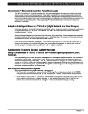
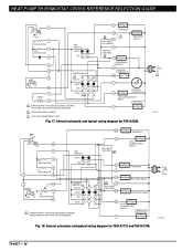
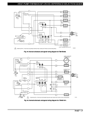
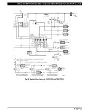
... SWITCH 1 POWER SUPPLY. Internal schematic and typical wiring diagram for T841A1308. 70-6627 • 15 RELAY SYSTEM MONITOR X LACO Y HEAT CHANGEOVER VALVE COMPRESSOR CONTACTOR O COOL CHANGEOVER VALVE CHP M6060A Fig. 16. HEAT PUMP THERMOSTAT CROSS REFERENCE/SELECTION GUIDE Typical System Hookup Diagrams L1 L2 (HOT) RTD 1 1 ODT 1 H1 C1 FALL H1/C1 ANTICIPATOR FAN SWITCH...
... SWITCH 1 POWER SUPPLY. Internal schematic and typical wiring diagram for T841A1308. 70-6627 • 15 RELAY SYSTEM MONITOR X LACO Y HEAT CHANGEOVER VALVE COMPRESSOR CONTACTOR O COOL CHANGEOVER VALVE CHP M6060A Fig. 16. HEAT PUMP THERMOSTAT CROSS REFERENCE/SELECTION GUIDE Typical System Hookup Diagrams L1 L2 (HOT) RTD 1 1 ODT 1 H1 C1 FALL H1/C1 ANTICIPATOR FAN SWITCH...
User Guide
Page 18
.... 17. HEAT RELAY AUX. HEAT LED (GREEN) B EM. HEAT OFF 1 RESET 4 COOL 1 POWER SUPPLY. COMPRESSOR MONITOR R OUTDOOR THERMOSTAT X2 T OUTDOOR O THERMISTOR COOL CHANGEOVER RELAY COMPRESSOR CONTACTOR Y 2 FIELD REMOVABLE JUMPER. 3 AUTO FAN IN EMERGENCY HEAT. HEAT LED (RED) W3 RELAY COOL CHANGEOVER RELAY...OVERLOAD PROTECTION AS REQUIRED. HEAT RELAY B HEAT CHANGEOVER RELAY COMPRESSOR CONTACTOR Y Fig. 18. L2 1 L1 (HOT) M13249 70-6627 • 16 HT. HT. HEAT LED (RED) FAN RELAY 2 F AUX. HEAT OFF COOL 1 POWER SUPPLY. HEAT PUMP TH ERMOSTAT CROSS REFERENCE/...
.... 17. HEAT RELAY AUX. HEAT LED (GREEN) B EM. HEAT OFF 1 RESET 4 COOL 1 POWER SUPPLY. COMPRESSOR MONITOR R OUTDOOR THERMOSTAT X2 T OUTDOOR O THERMISTOR COOL CHANGEOVER RELAY COMPRESSOR CONTACTOR Y 2 FIELD REMOVABLE JUMPER. 3 AUTO FAN IN EMERGENCY HEAT. HEAT LED (RED) W3 RELAY COOL CHANGEOVER RELAY...OVERLOAD PROTECTION AS REQUIRED. HEAT RELAY B HEAT CHANGEOVER RELAY COMPRESSOR CONTACTOR Y Fig. 18. L2 1 L1 (HOT) M13249 70-6627 • 16 HT. HT. HEAT LED (RED) FAN RELAY 2 F AUX. HEAT OFF COOL 1 POWER SUPPLY. HEAT PUMP TH ERMOSTAT CROSS REFERENCE/...
User Guide
Page 19
... C815A OUTDOOR THERMISTOR T FAN RELAY G CHANGEOVER VALVE O R X2 OUTDOOR THERMOSTAT W AUX. Fig. 20. HEAT PUMP THERMOSTAT CROSS REFERENCE/SELECTION GUIDE H1/C1 ANTICIPATOR H1 C1 FALL FAN SWITCH AUTO ON W1 HEAT RELAY 1 W2 HEAT RELAY 2 B HEAT CHANGEOVER VALVE G FAN RELAY H2 ANTICIPATOR H2 FALL SYSTEM SWITCH HEAT OFF COOL 1 POWER SUPPLY. PROVIDE DISCONNECT MEANS AND OVERLOAD PROTECTION AS...
... C815A OUTDOOR THERMISTOR T FAN RELAY G CHANGEOVER VALVE O R X2 OUTDOOR THERMOSTAT W AUX. Fig. 20. HEAT PUMP THERMOSTAT CROSS REFERENCE/SELECTION GUIDE H1/C1 ANTICIPATOR H1 C1 FALL FAN SWITCH AUTO ON W1 HEAT RELAY 1 W2 HEAT RELAY 2 B HEAT CHANGEOVER VALVE G FAN RELAY H2 ANTICIPATOR H2 FALL SYSTEM SWITCH HEAT OFF COOL 1 POWER SUPPLY. PROVIDE DISCONNECT MEANS AND OVERLOAD PROTECTION AS...
User Guide
Page 20
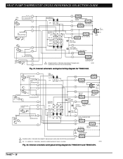
... typical wiring diagram for Y594G1419 and Y594G1476. 70-6627 • 18 HEAT AUTO COOL W2 E AUX. HT. HT. HT. RELAY L EM. COMPRESSOR CONTACTOR M8702 Fig. 21. HEAT RELAY CHECK LED (RED) COMPRESSOR FAULT X2 EM. Internal schematic and typical wiring diagram for Y594G1633. HEAT PUMP THERMOSTAT CROSS REFERENCE/SELECTION GUIDE FALL 1 H1 ANTICIPATOR 2 H1 4 6 H2 ANTICIPATOR...
... typical wiring diagram for Y594G1419 and Y594G1476. 70-6627 • 18 HEAT AUTO COOL W2 E AUX. HT. HT. HT. RELAY L EM. COMPRESSOR CONTACTOR M8702 Fig. 21. HEAT RELAY CHECK LED (RED) COMPRESSOR FAULT X2 EM. Internal schematic and typical wiring diagram for Y594G1633. HEAT PUMP THERMOSTAT CROSS REFERENCE/SELECTION GUIDE FALL 1 H1 ANTICIPATOR 2 H1 4 6 H2 ANTICIPATOR...
User Guide
Page 21
... REMOVABLE JUMPER. HEAT LED (GRN) AUX. HEAT OFF R L EM. HEAT PUMP THERMOSTAT CROSS REFERENCE/SELECTION GUIDE 1 2 H1 C1 FALL 3 4 H2 FALL 5 6 11 AUTO ON FAN SWITCH SYSTEM SWITCH EM. Fig. 24. HEAT LED (GREEN) EM. HEAT LED (RED) G FAN RELAY W 2 U AUX. HEATER RELAY B COMPRESSOR MONITOR F R 1 L1 (HOT) L2 T X2 OUTDOOR THERMOSTAT O COMPRESSOR CONTACTOR Y OUTDOOR SENSOR COOL CHANGEOVER VALVE M8701...
... REMOVABLE JUMPER. HEAT LED (GRN) AUX. HEAT OFF R L EM. HEAT PUMP THERMOSTAT CROSS REFERENCE/SELECTION GUIDE 1 2 H1 C1 FALL 3 4 H2 FALL 5 6 11 AUTO ON FAN SWITCH SYSTEM SWITCH EM. Fig. 24. HEAT LED (GREEN) EM. HEAT LED (RED) G FAN RELAY W 2 U AUX. HEATER RELAY B COMPRESSOR MONITOR F R 1 L1 (HOT) L2 T X2 OUTDOOR THERMOSTAT O COMPRESSOR CONTACTOR Y OUTDOOR SENSOR COOL CHANGEOVER VALVE M8701...
User Guide
Page 22
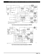
... diagram for Y594R1425. 70-6627 • 20 LED (RED) AUX. HEAT OFF COOL 11 1 POWER SUPPLY. HT. O COOL CHANGEOVER VALVE L COMPRESSOR MONITOR FAN RELAY G R EM. RELAY X 3 X2 HEAT CHANGEOVER VALVE B W1 RELAY W1 2 COMPRESSOR CONTACTOR Y L1 (HOT) L2 1 M8713 Fig. 25. HT. HT. HEAT PUMP THERMOSTAT CROSS REFERENCE/SELECTION GUIDE W3 W3 RELAY H1 ANTICIPATOR 1 C ANTICIPATOR 2 FAN...
... diagram for Y594R1425. 70-6627 • 20 LED (RED) AUX. HEAT OFF COOL 11 1 POWER SUPPLY. HT. O COOL CHANGEOVER VALVE L COMPRESSOR MONITOR FAN RELAY G R EM. RELAY X 3 X2 HEAT CHANGEOVER VALVE B W1 RELAY W1 2 COMPRESSOR CONTACTOR Y L1 (HOT) L2 1 M8713 Fig. 25. HT. HT. HEAT PUMP THERMOSTAT CROSS REFERENCE/SELECTION GUIDE W3 W3 RELAY H1 ANTICIPATOR 1 C ANTICIPATOR 2 FAN...
User Guide
Page 23
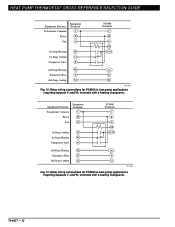
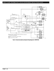
...OVERLOAD PROTECTION AS REQUIRED. 2 DENOTES THERMOSTAT TO SUBBASE INTERCONNECT. B HEAT CHANGEOVER VALVE HIGH LIMIT HEAT 1 1 POWER SUPPLY. HT. HEAT PUMP THERMOSTAT CROSS REFERENCE/SELECTION GUIDE 2 POWER SUPPLY THERMOSTAT LOGIC CIRCUIT SUBBASE LOGIC/ CONTROL CIRCUIT FAN SWITCH ON AUTO HIGH LIMIT EM. COOL CHANGEOVER VALVE O COOL C. Y X1 3 CHECK LED...FAN RELAY G SYSTEM SWITCH EM. LED (RED) R C/X AUX. RELAY E EM. LED (GREEN) L HEAT 2 MONITOR W2 AUX. HT. Typical wiring diagram for T8611G1004 and T8611G1103. O. L1 (HOT) L2 1 70-6627 • 21
...OVERLOAD PROTECTION AS REQUIRED. 2 DENOTES THERMOSTAT TO SUBBASE INTERCONNECT. B HEAT CHANGEOVER VALVE HIGH LIMIT HEAT 1 1 POWER SUPPLY. HT. HEAT PUMP THERMOSTAT CROSS REFERENCE/SELECTION GUIDE 2 POWER SUPPLY THERMOSTAT LOGIC CIRCUIT SUBBASE LOGIC/ CONTROL CIRCUIT FAN SWITCH ON AUTO HIGH LIMIT EM. COOL CHANGEOVER VALVE O COOL C. Y X1 3 CHECK LED...FAN RELAY G SYSTEM SWITCH EM. LED (RED) R C/X AUX. RELAY E EM. LED (GREEN) L HEAT 2 MONITOR W2 AUX. HT. Typical wiring diagram for T8611G1004 and T8611G1103. O. L1 (HOT) L2 1 70-6627 • 21
User Guide
Page 30
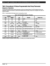
... Em Heat Stage 1 heating B or O/Ba, E and G (select models) Auto Em Heat Stage 2 heating B or O/Ba, E and W2 and G (select models) Auto Auto None O/Ba, O or Bb a Configure O/B (select models) in the Energize column vary depending on the Fan and System Settings. HEAT PUMP THERMOSTAT CROSS REFERENCE/SELECTION GUIDE T8611 Chronotherm IV Deluxe Programmable Heat Pump Thermostat Sequence of Operation The thermostat energizes...
... Em Heat Stage 1 heating B or O/Ba, E and G (select models) Auto Em Heat Stage 2 heating B or O/Ba, E and W2 and G (select models) Auto Auto None O/Ba, O or Bb a Configure O/B (select models) in the Energize column vary depending on the Fan and System Settings. HEAT PUMP THERMOSTAT CROSS REFERENCE/SELECTION GUIDE T8611 Chronotherm IV Deluxe Programmable Heat Pump Thermostat Sequence of Operation The thermostat energizes...
User Guide
Page 35
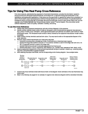
... for Using This Heat Pump Cross Reference This cross reference, alphabetized by the equipment manufacturer model number, if available. 3. The Honeywell model number is typical. - See example below. To use the corresponding control hookup diagram. Make a listing of wiring terminals used for first stage heat and cool, or to write on the new thermostat may find a Chronotherm...
... for Using This Heat Pump Cross Reference This cross reference, alphabetized by the equipment manufacturer model number, if available. 3. The Honeywell model number is typical. - See example below. To use the corresponding control hookup diagram. Make a listing of wiring terminals used for first stage heat and cool, or to write on the new thermostat may find a Chronotherm...


