User Guide
Page 2
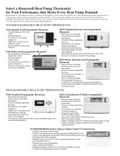
... heat/one cool; ming easier for quick and easy access to -read backlit display. • Adaptive Intelligent Recovery™ optimizes heat pump energy savings. • Outdoor temperature display available with optional outdoor temperature sensor. Honeywell heat pump thermostats are ideal for quick, easy readability. • Fan and system switches are located by LCD for the installer and the homeowner. • Easy-to-read backlit display. • Most frequently used for optimum temperature control...
... heat/one cool; ming easier for quick and easy access to -read backlit display. • Adaptive Intelligent Recovery™ optimizes heat pump energy savings. • Outdoor temperature display available with optional outdoor temperature sensor. Honeywell heat pump thermostats are ideal for quick, easy readability. • Fan and system switches are located by LCD for the installer and the homeowner. • Easy-to-read backlit display. • Most frequently used for optimum temperature control...
User Guide
Page 3
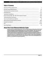
... Operation 26-28 Thermostat Manufacturer Cross Reference ...29-32 Tips for Using This Heat Pump Cross Reference ... 33 Wiring Connections for Honeywell Heat Pump Thermostats 34-35 Manufacturer Cross Reference ...36-116 Index ...117-118 Index to heat pump thermostat applications. HEAT PUMP THERMOSTAT CROSS REFERENCE/SELECTION GUIDE Table of Contents About This Cross Reference/Selection Guide ... 1 Heat Pump Thermostat Model Specifications ... 2-4 Thermostat Descriptions and General Information ... 5-12 Understanding Circuits ...13-14 Typical System Hookup Diagrams...
... Operation 26-28 Thermostat Manufacturer Cross Reference ...29-32 Tips for Using This Heat Pump Cross Reference ... 33 Wiring Connections for Honeywell Heat Pump Thermostats 34-35 Manufacturer Cross Reference ...36-116 Index ...117-118 Index to heat pump thermostat applications. HEAT PUMP THERMOSTAT CROSS REFERENCE/SELECTION GUIDE Table of Contents About This Cross Reference/Selection Guide ... 1 Heat Pump Thermostat Model Specifications ... 2-4 Thermostat Descriptions and General Information ... 5-12 Understanding Circuits ...13-14 Typical System Hookup Diagrams...
User Guide
Page 7
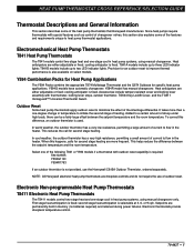
... is fixed; Electronic Non-programmable Heat Pump Thermostats T8411 Electronic Heat Pump Thermostats The T8411 models control two-stage heat and one -stage cool in memory (no batteries required) and retained during power failures. cooling anticipator is selectable at 3, 6, or 9 cph. Y594G models have automatic changeover; second stage heat anticipation is fixed. Setpoints are droopless controls and do not require the use the Honeywell C815A Outdoor Thermistor, ordered separately. cooling anticipator is not provided, use of outdoor reset. It takes...
... is fixed; Electronic Non-programmable Heat Pump Thermostats T8411 Electronic Heat Pump Thermostats The T8411 models control two-stage heat and one -stage cool in memory (no batteries required) and retained during power failures. cooling anticipator is selectable at 3, 6, or 9 cph. Y594G models have automatic changeover; second stage heat anticipation is fixed. Setpoints are droopless controls and do not require the use the Honeywell C815A Outdoor Thermistor, ordered separately. cooling anticipator is not provided, use of outdoor reset. It takes...
User Guide
Page 8
...; Electronic Programmable Heat Pump Thermostats T8011 Standard Electronic Heat Pump Thermostats The T8011 models provide two-stage heat and one -stage cool in memory (no batteries required) and retained during power outages. Battery backup, with low battery indication, maintains clock and memory during power failures. Jumper the Y2 and W2 terminals.a 3. First stage heat anticipation is wired to control multistage heat pump equipment. However, there is no jumper is a three-stage heat/two-stage cool thermostat used to the Y2 terminal. Configure the O/B terminal...
...; Electronic Programmable Heat Pump Thermostats T8011 Standard Electronic Heat Pump Thermostats The T8011 models provide two-stage heat and one -stage cool in memory (no batteries required) and retained during power outages. Battery backup, with low battery indication, maintains clock and memory during power failures. Jumper the Y2 and W2 terminals.a 3. First stage heat anticipation is wired to control multistage heat pump equipment. However, there is no jumper is a three-stage heat/two-stage cool thermostat used to the Y2 terminal. Configure the O/B terminal...
User Guide
Page 9
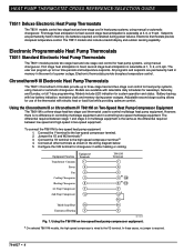
... Chronotherm® IV Thermostats with programmable fan operation are ideal for night setback and energy savings. These models provide full 7-day programming capability. Conventional recovery starts recovery at the beginning of heating. * The O terminal is connected to the coil terminals on a call for heat, the thermostat Y terminal activates the first stage of the programmed time period and uses the equipment to the installation. Honeywell does not recommend this requirement, a separate switching relay must be energized...
... Chronotherm® IV Thermostats with programmable fan operation are ideal for night setback and energy savings. These models provide full 7-day programming capability. Conventional recovery starts recovery at the beginning of heating. * The O terminal is connected to the coil terminals on a call for heat, the thermostat Y terminal activates the first stage of the programmed time period and uses the equipment to the installation. Honeywell does not recommend this requirement, a separate switching relay must be energized...
User Guide
Page 10
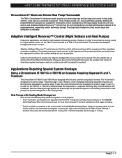
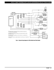
... GUIDE Equipment Equipment Function Terminals Power R 1st Stage Cool Y1 2nd Stage Cool Y2 Fan G 1st Stage Heat W1 2nd Stage Heat W2 Transformer Common C T8611M Terminals R Y2 G W2 C Y Heating Changeover B O R8222B Relay B M13231 Fig. 2. Installing an R8222B Switching Relay on heat pumps requiring heating mode changeover. Heat Pumps with Cooling Mode Changeover Here is how the switching relay allows the system to work properly: * The Y terminal is connected to the coil terminals of the R8222B Switching Relay. Equipment Function Power 1st Stage Cool 2nd Stage...
... GUIDE Equipment Equipment Function Terminals Power R 1st Stage Cool Y1 2nd Stage Cool Y2 Fan G 1st Stage Heat W1 2nd Stage Heat W2 Transformer Common C T8611M Terminals R Y2 G W2 C Y Heating Changeover B O R8222B Relay B M13231 Fig. 2. Installing an R8222B Switching Relay on heat pumps requiring heating mode changeover. Heat Pumps with Cooling Mode Changeover Here is how the switching relay allows the system to work properly: * The Y terminal is connected to the coil terminals of the R8222B Switching Relay. Equipment Function Power 1st Stage Cool 2nd Stage...
User Guide
Page 11
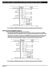
... in emergency heat mode for electronic thermostats. HT. Heat Pump Manufacturer Relay Wiring Connections The wiring connections for some thermostats to specific types of systems. To change the fan operation on some types of heat pump equipment require a separate relay for the wiring connections of these types of equipment. Relay wiring connections for proper operation. 70-6627 • 9 Heat) G G (Fan) Thermostat R8222B Relay Equipment M13232 Fig. 4 Changing fan operation in EM. Existing Control Equipment Function Terminal Designation Transformer Common C 1st Stage...
... in emergency heat mode for electronic thermostats. HT. Heat Pump Manufacturer Relay Wiring Connections The wiring connections for some thermostats to specific types of systems. To change the fan operation on some types of heat pump equipment require a separate relay for the wiring connections of these types of equipment. Relay wiring connections for proper operation. 70-6627 • 9 Heat) G G (Fan) Thermostat R8222B Relay Equipment M13232 Fig. 4 Changing fan operation in EM. Existing Control Equipment Function Terminal Designation Transformer Common C 1st Stage...
User Guide
Page 25
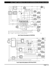
... SENSOR THERMOSTAT LOGIC STAGE 2 RELAY STAGE 1 RELAY SYSTEM SWITCH EM. M11333 Fig. 29. LED (RED) R C AUX. LED (GREEN) L MONITOR W2 AUX. HEAT OFF COOL L1 R (HOT) L2 AUXILARY HEAT RELAY 1 W2 RELAY L CHANGEOVER VALVE HEAT B CHANGEOVER VALVE COOL O COMPRESSOR CONTACTOR Y 2 COMPRESSOR CONTACTOR HEAT W1 POWER SUPPLY FAN SWITCH ON AUTO EMERGENCY HEAT RELAY E FAN RELAY G C 1 POWER SUPPLY. HT. PROVIDE DISCONNECT MEANS AND OVERLOAD PROTECTION AS REQUIRED. 2 REMOVE JUMPER FOR SYSTEM WITH ISOLATED STAGE 1 HEATING AND COOLING CONNECTIONS. 3 DENOTES THERMOSTAT...
... SENSOR THERMOSTAT LOGIC STAGE 2 RELAY STAGE 1 RELAY SYSTEM SWITCH EM. M11333 Fig. 29. LED (RED) R C AUX. LED (GREEN) L MONITOR W2 AUX. HEAT OFF COOL L1 R (HOT) L2 AUXILARY HEAT RELAY 1 W2 RELAY L CHANGEOVER VALVE HEAT B CHANGEOVER VALVE COOL O COMPRESSOR CONTACTOR Y 2 COMPRESSOR CONTACTOR HEAT W1 POWER SUPPLY FAN SWITCH ON AUTO EMERGENCY HEAT RELAY E FAN RELAY G C 1 POWER SUPPLY. HT. PROVIDE DISCONNECT MEANS AND OVERLOAD PROTECTION AS REQUIRED. 2 REMOVE JUMPER FOR SYSTEM WITH ISOLATED STAGE 1 HEATING AND COOLING CONNECTIONS. 3 DENOTES THERMOSTAT...
User Guide
Page 27
... IN COOL MODE. 4 FACTORY-INSTALLED JUMPER; REMOVE IF A HEAT RELAY IS CONNECTED TO W1. 3 O/B G FAIL LED (RED) X1 X2 CHECK LED (RED) L OT 2 OT Fig. 31. Typical wiring diagram for T8611G2002 and T8611G2028. HEAT PUMP THERMOSTAT CROSS REFERENCE/SELECTION GUIDE L1 1 (HOT) L2 R POWER SUPPLY THERMOSTAT LOGIC W2 W1 E C COMPRESSOR CONTACTOR HEAT W1 AUXILIARY HEAT RELAY W2 4 EMERGENCY HEAT RELAY E COMPRESSOR CONTACTOR Y1 Y O/B G 1 POWER SUPPLY. PROVIDE DISCONNECT MEANS AND OVERLOAD PROTECTION AS REQUIRED. 2 WIRES TO OT TERMINALS SHOULD NOT...
... IN COOL MODE. 4 FACTORY-INSTALLED JUMPER; REMOVE IF A HEAT RELAY IS CONNECTED TO W1. 3 O/B G FAIL LED (RED) X1 X2 CHECK LED (RED) L OT 2 OT Fig. 31. Typical wiring diagram for T8611G2002 and T8611G2028. HEAT PUMP THERMOSTAT CROSS REFERENCE/SELECTION GUIDE L1 1 (HOT) L2 R POWER SUPPLY THERMOSTAT LOGIC W2 W1 E C COMPRESSOR CONTACTOR HEAT W1 AUXILIARY HEAT RELAY W2 4 EMERGENCY HEAT RELAY E COMPRESSOR CONTACTOR Y1 Y O/B G 1 POWER SUPPLY. PROVIDE DISCONNECT MEANS AND OVERLOAD PROTECTION AS REQUIRED. 2 WIRES TO OT TERMINALS SHOULD NOT...
User Guide
Page 35
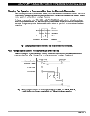
... controls temperature, indoor air quality, ventilation, humidity, and zoning. The Honeywell model number is typical. - You may not be used for first stage heat and cool, or to those terminals shown with lines to C R M13251 7. Connect only those diagrams in this cross reference. 4. Identify if device has manual or automatic changeover from manual changeover to write on the diagram. e.g., a working family may have. - After selecting the proper thermostat, use...
... controls temperature, indoor air quality, ventilation, humidity, and zoning. The Honeywell model number is typical. - You may not be used for first stage heat and cool, or to those terminals shown with lines to C R M13251 7. Connect only those diagrams in this cross reference. 4. Identify if device has manual or automatic changeover from manual changeover to write on the diagram. e.g., a working family may have. - After selecting the proper thermostat, use...
User Guide
Page 37
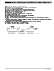
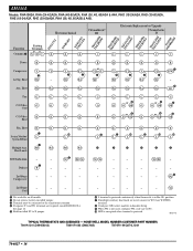
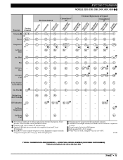
... remove factory-installed jumper. µ If multiple auxiliary heat loads are used, connect to W2 (Aux W8900B) terminal. ¸ Used on two-speed compressor heat pump applications. ¹ Used on heat pumps that energize the compressor on both first stage cooling and first stage heating through a common Y terminal. Ƹ Q674F1022 switching subbase available when separate first stage heat and cool terminals are required, install R8222D1014; (See page 12.) ² When W2 is not used . ƺ Jumper W2 and Y2 if stage 2 heating and cooling...
... remove factory-installed jumper. µ If multiple auxiliary heat loads are used, connect to W2 (Aux W8900B) terminal. ¸ Used on two-speed compressor heat pump applications. ¹ Used on heat pumps that energize the compressor on both first stage cooling and first stage heating through a common Y terminal. Ƹ Q674F1022 switching subbase available when separate first stage heat and cool terminals are required, install R8222D1014; (See page 12.) ² When W2 is not used . ƺ Jumper W2 and Y2 if stage 2 heating and cooling...
User Guide
Page 38
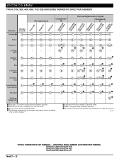
... in Installer Setup. ¾ When W2 is not used , connect to W2 (Aux W8900B) terminal. º Configure O/B (select models) in Em. X1 X2 - - - - ¾ - - Cool ³ Not available on all models. · Do not remove factory-installed jumper. » Terminal must be connected to the transformer common. ¿ If separate Y1 and W1 terminals are used , configure W2 cycle rate to X jumper. position. ¶ If multiple auxiliary heat loads are required, install R8222D1014. AMANA Models...
... in Installer Setup. ¾ When W2 is not used , connect to W2 (Aux W8900B) terminal. º Configure O/B (select models) in Em. X1 X2 - - - - ¾ - - Cool ³ Not available on all models. · Do not remove factory-installed jumper. » Terminal must be connected to the transformer common. ¿ If separate Y1 and W1 terminals are used , configure W2 cycle rate to X jumper. position. ¶ If multiple auxiliary heat loads are required, install R8222D1014. AMANA Models...
User Guide
Page 41
...; L L L ¾ ¾ L L EM. Compressor - See Fig. 26. ¶ Field-installed X2 to X jumper (provided). º If multiple auxiliary heat loads are used , configure W2 cycle rate to NC. » Terminal X (C, X1) must be connected to W2 (Aux W8900B) terminal. ¾ LED is energized when terminal is for multiple second stage loads such as contactors, sequencers, or relays. ´ Do not remove factory-installed jumper. ² Optional CHECK LED...
...; L L L ¾ ¾ L L EM. Compressor - See Fig. 26. ¶ Field-installed X2 to X jumper (provided). º If multiple auxiliary heat loads are used , configure W2 cycle rate to NC. » Terminal X (C, X1) must be connected to W2 (Aux W8900B) terminal. ¾ LED is energized when terminal is for multiple second stage loads such as contactors, sequencers, or relays. ´ Do not remove factory-installed jumper. ² Optional CHECK LED...
User Guide
Page 42
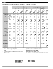
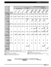
... Stage - - - - Compressor ³ Configure O/B (select models) in Installer Setup. · When W2 is not used, configure W2 cycle rate to NC. » If multiple auxiliary heat loads are used, connect to X jumper (provided). ¾ LED is energized when terminal is powered. µ L terminal is powered continuously when thermostat is for multiple second stage heating loads such as contactors, sequencers, or relays. HONEYWELL MODEL NUMBER T872N1036/Q672F1299 T874R1129/Q674L1181 T872N1164/Q672L1185 T874R1152/Q674L1207 T874N1024/Q674F1261 Aux...
... Stage - - - - Compressor ³ Configure O/B (select models) in Installer Setup. · When W2 is not used, configure W2 cycle rate to NC. » If multiple auxiliary heat loads are used, connect to X jumper (provided). ¾ LED is energized when terminal is powered. µ L terminal is powered continuously when thermostat is for multiple second stage heating loads such as contactors, sequencers, or relays. HONEYWELL MODEL NUMBER T872N1036/Q672F1299 T874R1129/Q674L1181 T872N1164/Q672L1185 T874R1152/Q674L1207 T874N1024/Q674F1261 Aux...

User Guide
Page 43
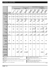
... Indication X - E E W3 W3 - - Compressor - - - ³ Configure O/B (select models) in Em. See Fig. 26. ¾ Field-installed X2 to X jumper (provided). µ If multiple auxiliary heat loads are used , configure W2 cycle rate to NC. » If provided on X1 and X2 terminals. Ƹ L terminal is powered continuously when thermostat is for multiple second stage heating loads such as contactors, sequencers, or relays. ´ Model 545 typical. HONEYWELL MODEL NUMBER (CUSTOMER PART NUMBER) T872G1166...
... Indication X - E E W3 W3 - - Compressor - - - ³ Configure O/B (select models) in Em. See Fig. 26. ¾ Field-installed X2 to X jumper (provided). µ If multiple auxiliary heat loads are used , configure W2 cycle rate to NC. » If provided on X1 and X2 terminals. Ƹ L terminal is powered continuously when thermostat is for multiple second stage heating loads such as contactors, sequencers, or relays. ´ Model 545 typical. HONEYWELL MODEL NUMBER (CUSTOMER PART NUMBER) T872G1166...
User Guide
Page 45
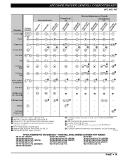
...; Terminal must be connected to the transformer common. · For auxiliary heat LED indication, jumper X2 to E. » Relay required (R8222B1067 typically) for wiring diagram. ¿ Optional LED indication activated with completed circuit on Q674. Heat E Common 1st Stage - M13148 TYPICAL THERMOSTATS AND SUBBASES - For emergency heat LED indication, jumper X2 to W2 on X1 and X2 terminals. ´ Configure O/B (select models) in Installer Setup. ² Configure Y1/W1 terminal in installer setup. ¶ L terminal is powered...
...; Terminal must be connected to the transformer common. · For auxiliary heat LED indication, jumper X2 to E. » Relay required (R8222B1067 typically) for wiring diagram. ¿ Optional LED indication activated with completed circuit on Q674. Heat E Common 1st Stage - M13148 TYPICAL THERMOSTATS AND SUBBASES - For emergency heat LED indication, jumper X2 to W2 on X1 and X2 terminals. ´ Configure O/B (select models) in Installer Setup. ² Configure Y1/W1 terminal in installer setup. ¶ L terminal is powered...
User Guide
Page 53
... to obtain replacements for multiple auxiliary heat loads such as shown. · Configure O/B (select models) in Installer Setup. » Optional LED indication activated with completed circuit on X1 and X2 terminals. ¿ R8222B1067 relays required to operate system. See page 10 for wiring diagram. ´ Terminal must be provided as contactors, sequencers, or relays. ¶ Do not remove factory-installed jumper. º Field-installed X2 to NC. Heat Aux. Compressor W3...
... to obtain replacements for multiple auxiliary heat loads such as shown. · Configure O/B (select models) in Installer Setup. » Optional LED indication activated with completed circuit on X1 and X2 terminals. ¿ R8222B1067 relays required to operate system. See page 10 for wiring diagram. ´ Terminal must be provided as contactors, sequencers, or relays. ¶ Do not remove factory-installed jumper. º Field-installed X2 to NC. Heat Aux. Compressor W3...
User Guide
Page 54
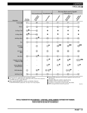
... transformer common. · When W2 is not used, configure W2 cycle rate to NC. » Do not remove factory-installed jumper. ¿ To eliminate automatic fan in emergency heat mode, connect switching relay as shown on page 9. ´ Configure O/B (select models) in Installer Setup. ² LED is energized when terminal is powered. ¶ L terminal is powered continuously when thermostat is in Em. HONEYWELL MODEL NUMBER (CUSTOMER PART NUMBER) T874G1501 (3600-375)/Q674F1378 T874G1576 (3600-373)/Q674F1402 T874R1368...
... transformer common. · When W2 is not used, configure W2 cycle rate to NC. » Do not remove factory-installed jumper. ¿ To eliminate automatic fan in emergency heat mode, connect switching relay as shown on page 9. ´ Configure O/B (select models) in Installer Setup. ² LED is energized when terminal is powered. ¶ L terminal is powered continuously when thermostat is in Em. HONEYWELL MODEL NUMBER (CUSTOMER PART NUMBER) T874G1501 (3600-375)/Q674F1378 T874G1576 (3600-373)/Q674F1402 T874R1368...
User Guide
Page 59
... Installer Setup. ² Optional LED indication activated with improved zero droop performance. » Do not remove factory-installed jumper. ¿ Optional CHECK LED on X1 and X2 terminals. ¶ LED is energized when terminal is powered. º L terminal is powered continuously when thermostat is not used, configure W2 cycle rate to transformer common. · Tape off. M13180 3AAT86B1A1 3AAT83F1B2 TYPICAL THERMOSTATS AND SUBBASES - Heat Aux. W2 Compressor ³ Terminal X (C) must be connected...
... Installer Setup. ² Optional LED indication activated with improved zero droop performance. » Do not remove factory-installed jumper. ¿ Optional CHECK LED on X1 and X2 terminals. ¶ LED is energized when terminal is powered. º L terminal is powered continuously when thermostat is not used, configure W2 cycle rate to transformer common. · Tape off. M13180 3AAT86B1A1 3AAT83F1B2 TYPICAL THERMOSTATS AND SUBBASES - Heat Aux. W2 Compressor ³ Terminal X (C) must be connected...
User Guide
Page 60
... multiple auxiliary heat loads are used , configure W2 cycle rate to transformer common. » Tape off . Fan G G G G G G G G G G C/O Valve - P - - - - - Electronic thermostat replaces outdoor reset with TRADELINE® replacement thermostats. · Terminal X (C) must be connected to NC. ¸ LED is energized when terminal is powered. ¹ L terminal is powered continuously when thermostat is in Installer Setup. µ When W2 is for multiple auxiliary heat loads such as contactors, sequencers, or relays. ´ Do not remove factory-installed jumper. ²...
... multiple auxiliary heat loads are used , configure W2 cycle rate to transformer common. » Tape off . Fan G G G G G G G G G G C/O Valve - P - - - - - Electronic thermostat replaces outdoor reset with TRADELINE® replacement thermostats. · Terminal X (C) must be connected to NC. ¸ LED is energized when terminal is powered. ¹ L terminal is powered continuously when thermostat is in Installer Setup. µ When W2 is for multiple auxiliary heat loads such as contactors, sequencers, or relays. ´ Do not remove factory-installed jumper. ²...


