Honeywell HPFF12 Support and Manuals
Get Help and Manuals for this Honeywell item
View All Support Options Below
Free Honeywell HPFF12 manuals!
Problems with Honeywell HPFF12?
Ask a Question
Free Honeywell HPFF12 manuals!
Problems with Honeywell HPFF12?
Ask a Question
Popular Honeywell HPFF12 Manual Pages
Operation Manual - Page 5
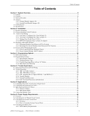
... 5.3.2: Split Alarm Mode ...45 5.4: Connecting Multiple Units ...46
Section 6: Power Supply Requirements 48 6.1: Overview...48 6.2: Calculating the AC Branch Circuit Current...48 6.3: Calculating the System Current Draw ...49 6.3.1: Overview ...49 6.3.2: How to Calculate System Current Draw 50 6.4: Calculating the Battery Size ...51 6.4.1: NFPA Battery Requirements ...51
HPFF12 NAC Expander -
Operation Manual - Page 9

...NAC outputs. P/N 53576:B 11/24/2010
9 It contains an internal battery charger capable of the most innovative fire alarm remote power supplies available that complies with 12 VDC or 24 VDC control panels. these models. (Equipment enclosures available through authorized Honeywell Fire Systems distributors.)
HPFF12, and HPFF12CM power supply models operate at 240 VAC/50 Hz. The Fire Alarm...
Operation Manual - Page 10

... Individual NAC Trouble LEDs • Maximum current for any one
Class A (Style Z) NACs (special application). - For lead-acid batteries only. - Filtered for full-wave-rectified polarity-reversing inputs or reducing spurious noise to accommodate Honeywell Fire Systems branded panels: Honeywell, Notifier, Gamewell FCI, Silent Knight, and FireLite Alarms.
• 24 VDC remote power supply. •...
Operation Manual - Page 11

... to the TB1 on page 17. 3. P/N 53576:B 11/24/2010
11 Start-up Procedure
1. Aids installer or repair personnel to find the location of initiating device input signal for Trouble indication at device or FACP. - Configure the power supply jumpers as described in Section 5, "Applications", on the AC mains circuit breaker connected to 22 AWG...
Operation Manual - Page 12

...system requires a common battery set, as a single battery connected to any user wiring point, including +24 VDC. Larger capacity batteries can charge in ...power supplies are located on the control circuit board; The HPFF12 models have an installed 12.0 A power supply. CAUTION: THE BATTERY CHARGER IS AUTOMATICALLY DISABLED DURING ALARM, SO BATTERIES
WILL NOT BE CHARGED WHEN THE POWER SUPPLY...
Operation Manual - Page 14

...; Supervised, non-power-limited. • Supports lead-acid type batteries only. • Float charge voltage: 26.6 VDC. • Charger disabled if battery voltage falls below for all outputs: HPFF12, HPFF12CM, HPFF12E, HPFF12CME:
12.0 A • Output circuit types:
- P/N 53576:B 11/24/2010 System Overview
Specifications
End-of 75 mA from batteries.
14
HPFF12 NAC Expander -
terminals...
Operation Manual - Page 30

....
See Section 2.5, "Power-Limited Wiring Requirements".
P/N 53576:B 11/24/2010 For a list of a six-output addressable module can be used in the HPFF12CM(E) units. Alternately, two outputs of compatible optional modules that can also be connected to remain in Figure 2.14 for Control & Relay Modules from Honeywell Fire Systems
30
HPFF12 NAC Expander - Mounting...
Operation Manual - Page 31

... Your specific application may be used in the large equipment enclosure. Any conduit knockouts may require different conduit knockouts to remain in the cabinet. For power-limited applications, use of this is available from any non-power-limited circuit wiring. Power-Limited Wiring Requirements
Installation
2.4.2 Mounting Six-Circuit Modules from Honeywell Fire System
2.5 Power-Limited...
Operation Manual - Page 39
... Auto
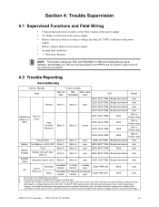
Field Wiring (NAC & +/- Section 4: Trouble Supervision
4.1 Supervised Functions and Field Wiring
• Field-wiring fault (short or open) on the NAC outputs of the power supply • AC failure or brownout at the power supply • Battery failure (no battery or battery voltage less than 20.5 VDC) condition at the power
supply • Battery charger failure on TB3 are not...
Operation Manual - Page 40

...
LED3: SIG3 TRBL
Steady Illumination
SW1 or Power cycle
LED4: SIG4 TRBL
Steady Illumination
SW1 or Power cycle
Ground Fault
(Note 1) (Note 2)
closed LED5: GF TRBL Steady Illumination Auto
Battery No battery or LED1: SIG1 TRBL
Steady Illumination
SW1 or Power cycle
Field Wiring (NAC & +/- Trouble Supervision
Trouble Reporting
Alarm
Alarm
Trouble contacts
Fault
TB2: AC
TB2: TB3...
Operation Manual - Page 45
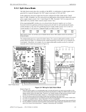
...two outputs of 1&2 and 3&4. Install jumpers supplied
with two synchronized (System Sensor protocol) and two non-synchronized outputs. When the power supply is connected to an addressable control module which controls output circuits 3 & 4. Section 4.1, "Supervised Functions and Field Wiring". 2. There must be used and mounted on . HPFF12 NAC Expander - Control module #2 will...
Operation Manual - Page 50

... ] =
Auxiliary Output Current Draw from Column 2 and Column 3 to the specifications of current that the power supply must support during a loss of devices in alarm. Current limitation on page 50.
• Calculation Column 1 -
Power Supply Requirements
Calculating the System Current Draw
6.3.2 How to Calculate System Current Draw
Use Table 6.4 to Table 6.5. Sum the total current for...
Operation Manual - Page 51

... the sum by 5 minutes in alarm
6.4.2 Selecting and Locating Batteries
Select batteries that meet or exceed the total ampere hours calculated in AH) required to support the power supply under the loss of the large equipment enclosure.
This total load determines the battery size (in Table 6.5. The power supply can be used for Standby and Alarm conditions, then sum...
Operation Manual - Page 59

...dimensions 18, 19, 20
Calculating AC branch circuit current 48 Battery Size 51 Power supply currents 48
System Current Draw 49, 50
Calculating fire alarm load 49 Calculating power supply requirements
procedures 48 Charger Disable... contacts (also see TROUBLE and AC FAIL) 11
G
Ground Fault Detection 41 Ground Fault Disable Jumper (J2) 12 ground monitoring 12
H
HPFF12CM installation 21 HPP31076 29
I...
Operation Manual - Page 60

... Dip switch settings
Programming input/output functions 36
S
Secondary power supply (defined) 49 Selecting and Locating Batteries 51 Selective silence 44
Semi-flush Mounting 19, 27 SIGNAL 1, SIGNAL 2 40, 41
Silencing 38 Silencing, see Selective silence Six-circuit modules 53
Specifications 13-16
Split alarm 38 Split alarm mode 45 Standards 7 Standby load calculations 51 Start...
Honeywell HPFF12 Reviews
We have not received any reviews for Honeywell yet.