Honeywell HPF24S6 Support and Manuals
Get Help and Manuals for this Honeywell item
View All Support Options Below
Free Honeywell HPF24S6 manuals!
Problems with Honeywell HPF24S6?
Ask a Question
Free Honeywell HPF24S6 manuals!
Problems with Honeywell HPF24S6?
Ask a Question
Popular Honeywell HPF24S6 Manual Pages
Installation Manual - Page 2
... systems must be installed in as many as horns and bells, can be technically compatible with conditions such as epilepsy.
• Studies have been properly maintained and replaced regularly. It is inadequate maintenance. Smoke detectors are not created by NFPA, local codes, and Authorities Having Jurisdiction (AHJ).
• Language and instructional requirements must be...
Installation Manual - Page 3
... unit until manuals are adequate for operation at 0-49º C/32-120º F and at a relative humidity 93% ± 2% RH (noncondensing) at his or her own expense. When possible, make all cable entries from digital apparatus set out in reduced terminal contact pressure and difficulty with long-term reliability:
WARNING - HPF24S Series Power Supplies -
Installation Manual - Page 4

... appropriate version for a specific application. If you think should be improved or corrected •Your suggestion for how to correct/improve documentation
Send email messages to:
FireSystems.TechPubs@honeywell.com
Please note this email address is for each product prior to commissioning any technical issues, please contact Technical Services.
4
HPF24S Series Power Supplies -
P/N 52751:F2...
Installation Manual - Page 5
...LED Indicators...10 1.6: Specifications...10 1.7: General...13
Section 2: Installation...14
2.1: Backbox Mounting ...14 2.2: NAC Circuit Wiring...16
2.2.1: Style Y (Class B) ...16 2.2.2: ZNAC-4 Class A Option Module...16 2.3: Addressable Module Mounting ...17 2.4: NEC Power-limited (Class 2) Wiring Requirements 18
Section 3: Programming Options 20
3.1: DIP Switch Settings ...21 3.2: Programmable...
Installation Manual - Page 8
... be configured as resettable or nonresettable • NAC Trouble LED - The HPF24S6E and HPF24S8E offer the same features as the HPF24S6 and HPF24S8 respectively. If an NAC or power supply fault is connected to the remote power supply input circuit(s). Output circuits may be configured as 24 VDC resettable or nonresettable power outputs. P/N 52751:F2 7/11/2014 The four...
Installation Manual - Page 9
...the power supply. - Install the power supply as described in "Jumpers" on page 20. 4. Make certain that the AC mains circuit breaker is 120 VAC, 60 Hz, 3.2 amps. - Connect primary power source wiring while observing the following procedure: - Configure the power supply jumpers as described in "Programming Options" on page 10. 2. Apply AC power by jumper JP1 • Power supply trouble...
Installation Manual - Page 10
...not connected.
-
indicates a charger fault or loss of the power supply circuit board. Primary AC Power - Note that a battery is disconnected, only the Battery Trouble LED will turn on.
1.6 Specifications
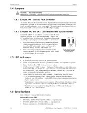
Refer to jumper the top two pins. TB1 • HPF24S6(C) & HPF24S8(C): 120 VAC, 60 Hz, 3.2 amps maximum • HPF24S6E & HPF24S8E: 240 VAC, 50 Hz, 1.6 amps maximum...
Installation Manual - Page 11
...
HPF24S Series Power Supplies - JP4 • Supervised, nonpower-limited • Supports lead acid ...Power Output - Maximum total continuous current for all outputs: HPF24S6 - 6.0 amps HPF24S8 - 8.0 amps • Output Circuit Types: -
Four resettable or nonresettable 24 VDC power...Specifications
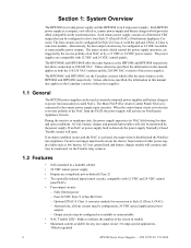
System Overview
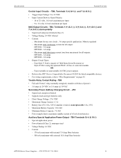
Control Input Circuits - Trouble Relay Contact Rating - Maximum total...
Installation Manual - Page 16
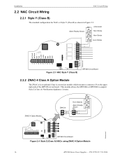
... Style Y (Class B) as shown in Figure 2.3.
This module allows the HPF24S6 or HPF24S8 to connector J3 on the upper right side of the HPF24S circuit board. ZNAC-4 Option Module
ZNAC-4
Horn Strobes
Alarm Polarity Shown
24fsclsa.wmf
J3 HPF24S Circuit Board
Figure 2.4 Style Z (Class A) NACs using ZNAC-4 Option Module
16
HPF24S Series Power Supplies -
Installation Manual - Page 22
...
ON
Wheelock
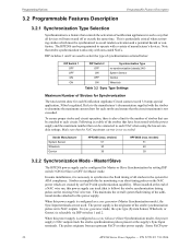
Table 3.2 Sync Type Settings
Maximum Number of a NAC wire run .
strobes) 51 40 39
3.2.2 Synchronization Mode -
In some installations, it is configured as a sync follower (Slave Synchronization mode), the power supply's NAC outputs track the strobe synchronization pulses present at the supply's Sync Input terminals. When this power supply can be synchronized to each...
Installation Manual - Page 27
... station is in trouble, the LED will blink the highest circuit number in this figure, refer to the SLC manual wiring conversion charts for legacy and newer versions of the modules.
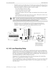
4.2 AC Loss Reporting Delay
The reporting of AC power by setting SW1 DIP switch 4 to the ON position. HPF24S Series Power Supplies - Changing the AC...
Installation Manual - Page 29
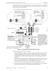
... screw terminals. HPF24S Series Power Supplies - This allows
Control Module*
EOL Power
Relay Module*
power wiring to remain inside the cabinet.
When the HPF-24S power supply is connected between TB4, Terminals 5 & 6 for independent trouble monitoring.
2. Power +).
3. An End-of -Line Resistor across TB4, Terminals 5 & 6). Break wires to the SLC manual wiring conversion charts for...
Installation Manual - Page 31

... Circuit. As an alternative, the trouble contacts at TB5 of the power supply can also be replaced with any setting but OFF/OFF)
3 = OFF...installed between terminals 5 & 6 for independent trouble monitoring.
3. For a list of -Line Resistor across Terminals 5 & 6).
Do not loop wires under screw terminals. The Output 4 door holder circuit will result in this figure, refer to the SLC manual...
Installation Manual - Page 33
... Aux. HPF24S Series Power Supplies - The power supply must be used for independent trouble monitoring.
2. P/N 52751:F2 7/11/2014
33 Break wires to Control Input 1 or a nonresettable power source, such as nonresettable by setting the power supply for Split Alarm mode. NOTE: All four outputs can be configured as resettable or all four can be installed between the auxiliary 24...
Installation Manual - Page 34
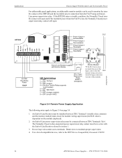
...-Line Resistor must be installed between TB4, Terminals 5 & 6. Do not loop wires under screw terminals. For a list of the modules.
24fsapp4tpH.wmf
Figure 5.4 Remote Power Supply Application
The following notes apply to the HPP Device Compatibility Document #54399.
34
HPF24S Series Power Supplies - If the HPF24S enters a trouble condition, the Normally Closed trouble contact will open...
Honeywell HPF24S6 Reviews
We have not received any reviews for Honeywell yet.