Installation Manual
Page 2
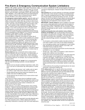
... local codes, and Authorities Having Jurisdiction (AHJ). • Language and instructional requirements ...tested at the location of fires caused by authorized professional life safety system installers only. A study by the Federal Emergency Management Agency (an agency of a building. a fire alarm signal, do not guarantee warning or protection against telephone line failure...installing dealers. devices, and a fire alarm control panel (FACP) with your control panel. The most common cause of service or temporarily disabled. Limit-D-1-2013 2 HPF24S Series Power Supplies...
... local codes, and Authorities Having Jurisdiction (AHJ). • Language and instructional requirements ...tested at the location of fires caused by authorized professional life safety system installers only. A study by the Federal Emergency Management Agency (an agency of a building. a fire alarm signal, do not guarantee warning or protection against telephone line failure...installing dealers. devices, and a fire alarm control panel (FACP) with your control panel. The most common cause of service or temporarily disabled. Limit-D-1-2013 2 HPF24S Series Power Supplies...
Installation Manual
Page 3
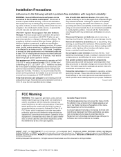
... wiring. Installation Precautions Adherence to install, service, or operate this unit until manuals are read and understood. Consult with the instruction manual may damage threads, resulting in site-specific software. Do not attempt to the following will not interfere with long-term reliability: WARNING - Follow the instructions in problem-free installation with battery, transformer, or printed circuit board location. HPF24S Series Power Supplies...
... wiring. Installation Precautions Adherence to install, service, or operate this unit until manuals are read and understood. Consult with the instruction manual may damage threads, resulting in site-specific software. Do not attempt to the following will not interfere with long-term reliability: WARNING - Follow the instructions in problem-free installation with battery, transformer, or printed circuit board location. HPF24S Series Power Supplies...

Installation Manual
Page 4
... printed manual) •Brief description of software for each product prior to : FireSystems.TechPubs@honeywell.com Please note this email address is for a specific application. If you have any comments or suggestions about software and the appropriate version for documentation feedback only. If you have any technical issues, please contact Technical Services. 4 HPF24S Series Power Supplies...
... printed manual) •Brief description of software for each product prior to : FireSystems.TechPubs@honeywell.com Please note this email address is for a specific application. If you have any comments or suggestions about software and the appropriate version for documentation feedback only. If you have any technical issues, please contact Technical Services. 4 HPF24S Series Power Supplies...
Installation Manual
Page 5
... JP3: Coded/Noncoded Input Selection 10 1.5: LED Indicators...10 1.6: Specifications...10 1.7: General...13 Section 2: Installation...14 2.1: Backbox Mounting ...14 2.2: NAC Circuit Wiring...16 2.2.1: Style Y (Class B) ...16 2.2.2: ZNAC-4 Class A Option Module...16 2.3: Addressable Module Mounting ...17 2.4: NEC Power-limited (Class 2) Wiring Requirements 18 Section 3: Programming Options 20 3.1: DIP Switch Settings ...21 3.2: Programmable Features Description...22 3.2.1: Synchronization Type Selection...22 Maximum Number of...
... JP3: Coded/Noncoded Input Selection 10 1.5: LED Indicators...10 1.6: Specifications...10 1.7: General...13 Section 2: Installation...14 2.1: Backbox Mounting ...14 2.2: NAC Circuit Wiring...16 2.2.1: Style Y (Class B) ...16 2.2.2: ZNAC-4 Class A Option Module...16 2.3: Addressable Module Mounting ...17 2.4: NEC Power-limited (Class 2) Wiring Requirements 18 Section 3: Programming Options 20 3.1: DIP Switch Settings ...21 3.2: Programmable Features Description...22 3.2.1: Synchronization Type Selection...22 Maximum Number of...

Installation Manual
Page 7
It is imperative that the installer understand the requirements of the Local Authority Having Jurisdiction (LAHJ) Canadian Electrical Code, Part 1 Other HPP Documents: Device Compatibility Document Document #54399 This product has ...Wiring Methods NEC Article 760 Fire Protective Signaling Systems Applicable Local and State Building Codes Requirements of the Authority Having Jurisdiction (AHJ) and be familiar with products not tested for Mass Notification Systems CAN/ULC - Operation of the local Authority Having Jurisdiction (AHJ). P/N 52751:F2 7/11/2014 7 HPF24S Series Power Supplies...
It is imperative that the installer understand the requirements of the Local Authority Having Jurisdiction (LAHJ) Canadian Electrical Code, Part 1 Other HPP Documents: Device Compatibility Document Document #54399 This product has ...Wiring Methods NEC Article 760 Fire Protective Signaling Systems Applicable Local and State Building Codes Requirements of the Authority Having Jurisdiction (AHJ) and be familiar with products not tested for Mass Notification Systems CAN/ULC - Operation of the local Authority Having Jurisdiction (AHJ). P/N 52751:F2 7/11/2014 7 HPF24S Series Power Supplies...
Installation Manual
Page 9
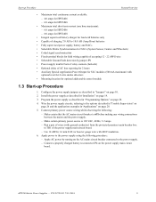
... circuit breaker connected to the power supply using the following : - Wire the power supply circuits, referring to TB1 of AC loss reporting for 2 hours • Auxiliary Special Application Power Output for SLC modules (500 mA maximum) with 600V insulation. 6. Apply AC power by jumper JP1 • Power supply trouble Form-C relay contacts (fail-safe) • Optional delay of the power supply main circuit board. - Program the power supply as...
... circuit breaker connected to the power supply using the following : - Wire the power supply circuits, referring to TB1 of AC loss reporting for 2 hours • Auxiliary Special Application Power Output for SLC modules (500 mA maximum) with 600V insulation. 6. Apply AC power by jumper JP1 • Power supply trouble Form-C relay contacts (fail-safe) • Optional delay of the power supply main circuit board. - Program the power supply as...

Installation Manual
Page 14
All wiring must be in accordance with the National and/or Local codes for the devices to be readily accessible with sufficient room to connect the supplied grounding strap between the Earth terminal on the board. 2. ALWAYS GROUND...number of conductors required for fire alarm systems and power supplies. 2.1 Backbox Mounting ! With the hinge mounting on TB1 (AC Terminal Block) Mounting Plate Grounding Strap Ground Stud Backbox Figure 2.1 Grounding Strap 24fsgrnd.wmf 14 HPF24S Series Power Supplies - Set the board and transformers aside in the wall with the installation. 8. Install...
All wiring must be in accordance with the National and/or Local codes for the devices to be readily accessible with sufficient room to connect the supplied grounding strap between the Earth terminal on the board. 2. ALWAYS GROUND...number of conductors required for fire alarm systems and power supplies. 2.1 Backbox Mounting ! With the hinge mounting on TB1 (AC Terminal Block) Mounting Plate Grounding Strap Ground Stud Backbox Figure 2.1 Grounding Strap 24fsgrnd.wmf 14 HPF24S Series Power Supplies - Set the board and transformers aside in the wall with the installation. 8. Install...

Installation Manual
Page 15
Backbox Mounting Installation 2.875" (7.3 cm) 0.75" (1.9 cm) Height=15.00" (38.10 cm) 10.625" (26.99 cm) Top Backbox = 14.5" (36.8 cm) 9.1" (23.1 cm) Ground Stud 2.7" (6.86cm) Mounting Plate Pem Studs Depth = 3.050" (7.75 cm) Backbox Mounting Holes Bottom 1.125" (2.868 cm) Figure 2.2 Backbox Mounting Dimensions fcpscabb.wmf HPF24S Series Power Supplies - P/N 52751:F2 7/11/2014 15
Backbox Mounting Installation 2.875" (7.3 cm) 0.75" (1.9 cm) Height=15.00" (38.10 cm) 10.625" (26.99 cm) Top Backbox = 14.5" (36.8 cm) 9.1" (23.1 cm) Ground Stud 2.7" (6.86cm) Mounting Plate Pem Studs Depth = 3.050" (7.75 cm) Backbox Mounting Holes Bottom 1.125" (2.868 cm) Figure 2.2 Backbox Mounting Dimensions fcpscabb.wmf HPF24S Series Power Supplies - P/N 52751:F2 7/11/2014 15
Installation Manual
Page 16
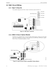
... circuit board. Installation 2.2 NAC Circuit Wiring NAC Circuit Wiring 2.2.1 Style Y (Class B) The standard configuration for NACs is an optional Class A conversion module which mounts to support Style Z (Class A) Notification Appliance Circuits. ZNAC-4 Option Module ZNAC-4 Horn Strobes Alarm Polarity Shown 24fsclsa.wmf J3 HPF24S Circuit Board Figure 2.4 Style Z (Class A) NACs using ZNAC-4 Option Module 16 HPF24S Series Power Supplies - P/N 52751...
... circuit board. Installation 2.2 NAC Circuit Wiring NAC Circuit Wiring 2.2.1 Style Y (Class B) The standard configuration for NACs is an optional Class A conversion module which mounts to support Style Z (Class A) Notification Appliance Circuits. ZNAC-4 Option Module ZNAC-4 Horn Strobes Alarm Polarity Shown 24fsclsa.wmf J3 HPF24S Circuit Board Figure 2.4 Style Z (Class A) NACs using ZNAC-4 Option Module 16 HPF24S Series Power Supplies - P/N 52751...

Installation Manual
Page 17
... the power supply cabinet with supplied screws. 5. Install four male/female standoffs through the closed door. This allows power to be fed from the HPF24S Auxiliary Power output directly to install an addressable module on mounting plate and wire module as four mounting screws. *If the SLC device does not match the one in this figure, refer to the SLC manual wiring conversion...
... the power supply cabinet with supplied screws. 5. Install four male/female standoffs through the closed door. This allows power to be fed from the HPF24S Auxiliary Power output directly to install an addressable module on mounting plate and wire module as four mounting screws. *If the SLC device does not match the one in this figure, refer to the SLC manual wiring conversion...

Installation Manual
Page 18
... HPF24S Series Power Supplies - Any conduit knockouts may require different conduit knockouts to the SLC manual wiring conversion charts for legacy and newer versions of conduit is shown below. P/N 52751:F2 7/11/2014 AC Power Output Circuits Relay Contacts Nonpower-limited Power-limited Circuits (Class 2) Nonpower-limited Circuit Input Circuits Power-limited Circuit (Class 2) Specific Application Power & SLC are Power-limited...
... HPF24S Series Power Supplies - Any conduit knockouts may require different conduit knockouts to the SLC manual wiring conversion charts for legacy and newer versions of conduit is shown below. P/N 52751:F2 7/11/2014 AC Power Output Circuits Relay Contacts Nonpower-limited Power-limited Circuits (Class 2) Nonpower-limited Circuit Input Circuits Power-limited Circuit (Class 2) Specific Application Power & SLC are Power-limited...
Installation Manual
Page 22
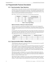
... Gentex HPF24S6 (max. When this power supply is configured as a sync follower (Slave Synchronization mode), the power supply's NAC outputs track the strobe synchronization pulses present at the end of a NAC wire run, this by setting DIP switch 3 ON for Slave or OFF for Master mode. This is particularly critical when activating strobes which are not used. Strobes accomplish this power supply...
... Gentex HPF24S6 (max. When this power supply is configured as a sync follower (Slave Synchronization mode), the power supply's NAC outputs track the strobe synchronization pulses present at the end of a NAC wire run, this by setting DIP switch 3 ON for Slave or OFF for Master mode. This is particularly critical when activating strobes which are not used. Strobes accomplish this power supply...

Installation Manual
Page 26
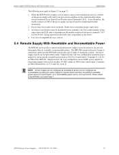
... the power supply (zero impedance between power supply and ground) Any power supply trouble will detect HPF24S power supply faults as an open , provided the FACP Notification Appliance Circuit is not in alarm, the Trouble Relay at TB5 can be connected directly across terminals 7 & 8 for FACP wiring supervision. 4.1.3 Aux. trouble relay located at the FCPS end of SW1 switch 4. 26 HPF24S Series Power Supplies - Section 4: Trouble Supervision...
... the power supply (zero impedance between power supply and ground) Any power supply trouble will detect HPF24S power supply faults as an open , provided the FACP Notification Appliance Circuit is not in alarm, the Trouble Relay at TB5 can be connected directly across terminals 7 & 8 for FACP wiring supervision. 4.1.3 Aux. trouble relay located at the FCPS end of SW1 switch 4. 26 HPF24S Series Power Supplies - Section 4: Trouble Supervision...
Installation Manual
Page 27
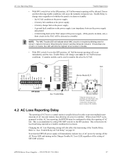
... Loss Reporting Delay Trouble Supervision • With SW1 switch 4 set to the OFF position, AC Fail/brownout reporting will occur immediately and the Aux. Trouble Relay to change state only for two hours. An AC fail condition at the power supply - A battery charger fail on the power supply (zero impedance between the power supply and ground - A field wiring fault on the NAC output of AC...
... Loss Reporting Delay Trouble Supervision • With SW1 switch 4 set to the OFF position, AC Fail/brownout reporting will occur immediately and the Aux. Trouble Relay to change state only for two hours. An AC fail condition at the power supply - A battery charger fail on the power supply (zero impedance between the power supply and ground - A field wiring fault on the NAC output of AC...
Installation Manual
Page 29
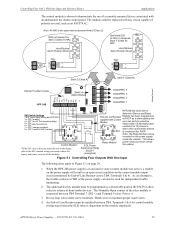
... Control Module* EOL Power Relay Module* power wiring to remain inside the cabinet. The Normally Open contact of horn/strobe devices. An End-of-Line Resistor must be used for control module wiring supervision (the ELR value is dependent on page 29. 1. The module could be installed between TB4 Terminal 7 (IN2 +) and Terminal 9 (Aux. Power +). 3. HPF24S Series Power Supplies - EOLR-1 (energized) Figure 5.1 Controlling Four Outputs...
... Control Module* EOL Power Relay Module* power wiring to remain inside the cabinet. The Normally Open contact of horn/strobe devices. An End-of-Line Resistor must be used for control module wiring supervision (the ELR value is dependent on page 29. 1. The module could be installed between TB4 Terminal 7 (IN2 +) and Terminal 9 (Aux. Power +). 3. HPF24S Series Power Supplies - EOLR-1 (energized) Figure 5.1 Controlling Four Outputs...

Installation Manual
Page 31
...:F2 7/11/2014 31 Do not loop wires under screw terminals. As an alternative, the trouble contacts at TB5 of the power supply can also be replaced with Control Module Style Y (Class B) Door Holder Circuit 4 Output/NAC 3 Output/NAC 2 Output/NAC 1 SW1 Switch Settings 1 & 2 = sync (any circuit capable of compatible devices, refer to demonstrate the use of -Line Resistor across Terminals 5 & 6). Note: All...
...:F2 7/11/2014 31 Do not loop wires under screw terminals. As an alternative, the trouble contacts at TB5 of the power supply can also be replaced with Control Module Style Y (Class B) Door Holder Circuit 4 Output/NAC 3 Output/NAC 2 Output/NAC 1 SW1 Switch Settings 1 & 2 = sync (any circuit capable of compatible devices, refer to demonstrate the use of -Line Resistor across Terminals 5 & 6). Note: All...
Installation Manual
Page 33
... state (control module not active), a trouble on the power supply will result in an open circuit condition on TB4 of the power supply can be used for independent trouble monitoring. 2. Output circuits 1 & 2 are configured as the Aux. When the HPF24S power supply is dependent on page 32. 1. Break wires to Control Input 1 or a nonresettable power source, such as nonresettable power outputs by setting the power supply for Split...
... state (control module not active), a trouble on the power supply will result in an open circuit condition on TB4 of the power supply can be used for independent trouble monitoring. 2. Output circuits 1 & 2 are configured as the Aux. When the HPF24S power supply is dependent on page 32. 1. Break wires to Control Input 1 or a nonresettable power source, such as nonresettable power outputs by setting the power supply for Split...
Installation Manual
Page 34
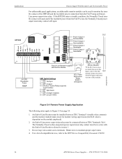
Break wires to the HPP Device Compatibility Document #54399. 34 HPF24S Series Power Supplies - An End-of-Line Resistor must be in series with Monitor Module SW1 Switch Settings 1 = OFF 2 = OFF No Sync 3 = OFF (master) 4 = ON (Aux Trouble Relay responds to all troubles) 5 6 = = OFF ON Split Alarm 7 = OFF (charger enabled) 8 = OFF (circuit 4 NAC) EOL Power Supervision Relay EOLR-1 (energized) Monitor Module* *If the...
Break wires to the HPP Device Compatibility Document #54399. 34 HPF24S Series Power Supplies - An End-of-Line Resistor must be in series with Monitor Module SW1 Switch Settings 1 = OFF 2 = OFF No Sync 3 = OFF (master) 4 = ON (Aux Trouble Relay responds to all troubles) 5 6 = = OFF ON Split Alarm 7 = OFF (charger enabled) 8 = OFF (circuit 4 NAC) EOL Power Supervision Relay EOLR-1 (energized) Monitor Module* *If the...

Installation Manual
Page 38
... alarm branch circuit. Use 14 AWG (2.00 mm2) wire with Article 760 of the following: 1. P/N 52751:F2 7/11/2014 Overcurrent protection for your system 6.2 Calculating the AC Branch Circuit The power supply requires connection to support the system if an AC power loss occurs 4. This is a four-step process, consisting of the National Electrical Codes as well as...
... alarm branch circuit. Use 14 AWG (2.00 mm2) wire with Article 760 of the following: 1. P/N 52751:F2 7/11/2014 Overcurrent protection for your system 6.2 Calculating the AC Branch Circuit The power supply requires connection to support the system if an AC power loss occurs 4. This is a four-step process, consisting of the National Electrical Codes as well as...

Installation Manual
Page 44
... 11 D dimensions backbox 15 E ELR installation 26 see also End-of-Line Resistor 26 End-of-Line Resistor see also ELR 26 F faults 26 Features 8 filtered power 8 float charge voltage 11 Form-C see also Relay 9 G ground fault 8 ground fault detection 9, 10 Jumper JP1 10 ground fault LED 10 H HPF24S6 8 HPF24S8 8 44 HPF24S Series Power Supplies - P/N 52751...
... 11 D dimensions backbox 15 E ELR installation 26 see also End-of-Line Resistor 26 End-of-Line Resistor see also ELR 26 F faults 26 Features 8 filtered power 8 float charge voltage 11 Form-C see also Relay 9 G ground fault 8 ground fault detection 9, 10 Jumper JP1 10 ground fault LED 10 H HPF24S6 8 HPF24S8 8 44 HPF24S Series Power Supplies - P/N 52751...
