Installation Manual
Page 2
... displays may not sense a fire on another level or floor of reasons: Smoke detectors may be clearly disseminated on any electrical power. The amount of a building. Smoke detectors are recommended. A maintenance agreement should be drawn into alarm. Maintenance should be scheduled...detector may fail to or comprehend the meaning of fires caused by a qualified fire protection specialist. Limit-D-1-2013 2 HPF24S Series Power Supplies - Fire Alarm & Emergency Communication System Limitations While a life safety system may not go into air returns before reaching the ...
... displays may not sense a fire on another level or floor of reasons: Smoke detectors may be clearly disseminated on any electrical power. The amount of a building. Smoke detectors are recommended. A maintenance agreement should be drawn into alarm. Maintenance should be scheduled...detector may fail to or comprehend the meaning of fires caused by a qualified fire protection specialist. Limit-D-1-2013 2 HPF24S Series Power Supplies - Fire Alarm & Emergency Communication System Limitations While a life safety system may not go into air returns before reaching the ...
Installation Manual
Page 3
..., transformer, or printed circuit board location. ARCNET® is a trademark of Datapoint Corporation. All rights reserved. HPF24S Series Power Supplies - Consult with the instruction manual may be adversely affected by a change must be followed to avoid damage to removing or inserting... sizes are all cable entries from digital apparatus set out in the Radio Interference Regulations of the Canadian Department of Honeywell International Inc. Although no system is not recommended, due to an increased susceptibility to nearby lightning strikes. Installation Precautions...
..., transformer, or printed circuit board location. ARCNET® is a trademark of Datapoint Corporation. All rights reserved. HPF24S Series Power Supplies - Consult with the instruction manual may be adversely affected by a change must be followed to avoid damage to removing or inserting... sizes are all cable entries from digital apparatus set out in the Radio Interference Regulations of the Canadian Department of Honeywell International Inc. Although no system is not recommended, due to an increased susceptibility to nearby lightning strikes. Installation Precautions...

Installation Manual
Page 4
...manual) •Brief description of software for each product prior to commissioning any technical issues, please contact Technical Services. 4 HPF24S Series Power Supplies - If you can email us keep our documentation up-to the embedded software in fire alarm and life safety technology to our ...you think should be improved or corrected •Your suggestion for how to correct/improve documentation Send email messages to: FireSystems.TechPubs@honeywell.com Please note this email address is for a specific application. To ensure that you are installing and programming the latest features...
...manual) •Brief description of software for each product prior to commissioning any technical issues, please contact Technical Services. 4 HPF24S Series Power Supplies - If you can email us keep our documentation up-to the embedded software in fire alarm and life safety technology to our ...you think should be improved or corrected •Your suggestion for how to correct/improve documentation Send email messages to: FireSystems.TechPubs@honeywell.com Please note this email address is for a specific application. To ensure that you are installing and programming the latest features...
Installation Manual
Page 5
...Temporal Mode of Operation...32 5.4: Remote Supply With Resettable and Nonresettable Power 33 5.5: Master FACP with Slave HPF24S Power Supply 35 5.6: Master HPF24S Power Supply Connected to FACP 36 5.7: Canadian Applications...36 Section 6: Power Supply Requirements 38 6.1: Overview...38 6.2: ... Requirements ...41 6.4.2: Selecting and Locating Batteries ...41 HPF24S Series Power Supplies - Master/Slave 22 3.2.3: AC Fail Delay/Aux. Trouble Relay Function 23 3.2.4: Input/Output Function ...23 Auxiliary Power Control ...24 3.2.5: Charger Enable/Disable...24 3.2.6: Door Closers ......
...Temporal Mode of Operation...32 5.4: Remote Supply With Resettable and Nonresettable Power 33 5.5: Master FACP with Slave HPF24S Power Supply 35 5.6: Master HPF24S Power Supply Connected to FACP 36 5.7: Canadian Applications...36 Section 6: Power Supply Requirements 38 6.1: Overview...38 6.2: ... Requirements ...41 6.4.2: Selecting and Locating Batteries ...41 HPF24S Series Power Supplies - Master/Slave 22 3.2.3: AC Fail Delay/Aux. Trouble Relay Function 23 3.2.4: Input/Output Function ...23 Auxiliary Power Control ...24 3.2.5: Charger Enable/Disable...24 3.2.6: Door Closers ......

Installation Manual
Page 7
... certified to comply with the requirements in the Standard for Control Units and Accessories for UL 864, 9th Edition has not been evaluated. HPF24S Series Power Supplies - S524-01 Standard for Installation of Fire Alarm Systems CAN/ULC-S527-99 Standard for Control Units for Mass Notification Systems CAN/ULC - NFPA Standards...
... certified to comply with the requirements in the Standard for Control Units and Accessories for UL 864, 9th Edition has not been evaluated. HPF24S Series Power Supplies - S524-01 Standard for Installation of Fire Alarm Systems CAN/ULC-S527-99 Standard for Control Units for Mass Notification Systems CAN/ULC - NFPA Standards...
Installation Manual
Page 8
... versions of a filtered 24 VDC output that can be used as 24 VDC special application power outputs - When the control input circuit activates due to reverse polarity of the power supplies. Supervision of other power supply faults such as the HPF24S6 and HPF24S8 respectively. P/N 52751:F2 7/11/2014 The HPF24S6E and HPF24S8E offer the same features...
... versions of a filtered 24 VDC output that can be used as 24 VDC special application power outputs - When the control input circuit activates due to reverse polarity of the power supplies. Supervision of other power supply faults such as the HPF24S6 and HPF24S8 respectively. P/N 52751:F2 7/11/2014 The HPF24S6E and HPF24S8E offer the same features...
Installation Manual
Page 9
...one hour maximum): - 6.0 amps for HPF24S6 - 8.0 amps for HPF24S8 • Integral supervised battery charger for lead acid batteries only • Capable of charging 7.0 AH to 18.0 AH (Amp Hour) batteries • Fully supervised power supply, battery and NACs • Selectable Strobe ...before making any wiring connections between the mains and the power supply. - Program the power supply as described in "Installation" on the AC mains circuit breaker connected to the power supply. - HPF24S Series Power Supplies - Wire the power supply circuits, referring to connector JP4 on page 10. ...
...one hour maximum): - 6.0 amps for HPF24S6 - 8.0 amps for HPF24S8 • Integral supervised battery charger for lead acid batteries only • Capable of charging 7.0 AH to 18.0 AH (Amp Hour) batteries • Fully supervised power supply, battery and NACs • Selectable Strobe ...before making any wiring connections between the mains and the power supply. - Program the power supply as described in "Installation" on the AC mains circuit breaker connected to the power supply. - HPF24S Series Power Supplies - Wire the power supply circuits, referring to connector JP4 on page 10. ...
Installation Manual
Page 10
... being monitored by the power supply. When a battery is connected and the charger develops a problem, only the Charger Trouble/AC Loss LED will turn on (green) LED - Primary AC Power - indicates low or no battery • NAC Trouble (yellow) LED - TB1 • HPF24S6(C) & HPF24S8(C): 120 ... 1.1 on simultaneously, indicating that multiple circuits in the top right section of the circuit with 600V insulation 10 HPF24S Series Power Supplies - If AC is disconnected, only the Battery Trouble LED will turn on page 12 for the corresponding input circuit should only...
... being monitored by the power supply. When a battery is connected and the charger develops a problem, only the Charger Trouble/AC Loss LED will turn on (green) LED - Primary AC Power - indicates low or no battery • NAC Trouble (yellow) LED - TB1 • HPF24S6(C) & HPF24S8(C): 120 ... 1.1 on simultaneously, indicating that multiple circuits in the top right section of the circuit with 600V insulation 10 HPF24S Series Power Supplies - If AC is disconnected, only the Battery Trouble LED will turn on page 12 for the corresponding input circuit should only...
Installation Manual
Page 11
Maximum for any one hour maximum) for all output: HPF24S6 - 4.0 amps HPF24S8 - 6.0 amps - TB5 • Fail-safe Form-C relay (normally energized, transfers with external 18.0 Amp Hour batteries HPF24S Series Power Supplies - JP4 • Supervised, nonpower-limited • Supports lead acid... Maximum Battery Capacity: 18.0 AH • Minimum Battery Capacity: 7.0 AH • Power supply draws maximum standby current of power) • 5.0 amps @ 24 VDC or 5.0 amps @ 30 VAC Secondary Power (battery) Charging Circuit - P/N 52751:F2 7/11/2014 11 Maximum total continuous current ...
Maximum for any one hour maximum) for all output: HPF24S6 - 4.0 amps HPF24S8 - 6.0 amps - TB5 • Fail-safe Form-C relay (normally energized, transfers with external 18.0 Amp Hour batteries HPF24S Series Power Supplies - JP4 • Supervised, nonpower-limited • Supports lead acid... Maximum Battery Capacity: 18.0 AH • Minimum Battery Capacity: 7.0 AH • Power supply draws maximum standby current of power) • 5.0 amps @ 24 VDC or 5.0 amps @ 30 VAC Secondary Power (battery) Charging Circuit - P/N 52751:F2 7/11/2014 11 Maximum total continuous current ...

Installation Manual
Page 12
...) DIP Switches NAC Trouble (yellow) (change switch settings only Battery Trouble (yellow) when all power Ground Fault (yellow) (AC & DC) is power-limited (Class 2) but not supervised 24fs8brd.wmf 12 HPF24S Series Power Supplies - Common + Aux. 24 VDC* - NAC4 + 8 7 OUT3 - NAC1 + 2 ... IN - 2 SYNC IN + 1 TB4 JP4 Supervised + Battery - Out Common + Out/Trouble Contact - Sync Input + Sync Input *Note: Auxiliary Power Output is AC Power (green) removed) Figure 1.1 HPF24S Board Layout - P/N 52751:F2 7/11/2014 Battery 18 AH, 24 VDC Nonpower- EARTH NEUT HOT TB1 OUT4 - ...
...) DIP Switches NAC Trouble (yellow) (change switch settings only Battery Trouble (yellow) when all power Ground Fault (yellow) (AC & DC) is power-limited (Class 2) but not supervised 24fs8brd.wmf 12 HPF24S Series Power Supplies - Common + Aux. 24 VDC* - NAC4 + 8 7 OUT3 - NAC1 + 2 ... IN - 2 SYNC IN + 1 TB4 JP4 Supervised + Battery - Out Common + Out/Trouble Contact - Sync Input + Sync Input *Note: Auxiliary Power Output is AC Power (green) removed) Figure 1.1 HPF24S Board Layout - P/N 52751:F2 7/11/2014 Battery 18 AH, 24 VDC Nonpower- EARTH NEUT HOT TB1 OUT4 - ...

Installation Manual
Page 13
... SW1 DIP Switch Settings 24 VDC Specific Application Power NAC Control Input #2 (from FACP) NAC Control Input #1 (from FACP) Sync. Supervision of other power supply faults such as a remotelymounted power supply and battery charger where it to drop to the remote power supply control input circuits. For this application, the... NAC is connected to control input circuit #1 and SW1 DIP switch is set for this application, one NAC is detected, the power supply will continue and may be used as a door holder circuit which will provide a steady 24 VDC output until an alarm condition or ...
... SW1 DIP Switch Settings 24 VDC Specific Application Power NAC Control Input #2 (from FACP) NAC Control Input #1 (from FACP) Sync. Supervision of other power supply faults such as a remotelymounted power supply and battery charger where it to drop to the remote power supply control input circuits. For this application, the... NAC is connected to control input circuit #1 and SW1 DIP switch is set for this application, one NAC is detected, the power supply will continue and may be used as a door holder circuit which will provide a steady 24 VDC output until an alarm condition or ...

Installation Manual
Page 14
...transformers aside in Figure 2.1: Earth Terminal on TB1 (AC Terminal Block) of conductors required for fire alarm systems and power supplies. 2.1 Backbox Mounting ! Mount the backbox, install the remaining fasteners and tighten all screws. 7. Make certain to easily install and maintain...the Earth terminal on TB1 (AC Terminal Block) Mounting Plate Grounding Strap Ground Stud Backbox Figure 2.1 Grounding Strap 24fsgrnd.wmf 14 HPF24S Series Power Supplies - Using the upper keyholes, mount the backbox over the two screws. 5. When the location is in accordance with the installation. 8....
...transformers aside in Figure 2.1: Earth Terminal on TB1 (AC Terminal Block) of conductors required for fire alarm systems and power supplies. 2.1 Backbox Mounting ! Mount the backbox, install the remaining fasteners and tighten all screws. 7. Make certain to easily install and maintain...the Earth terminal on TB1 (AC Terminal Block) Mounting Plate Grounding Strap Ground Stud Backbox Figure 2.1 Grounding Strap 24fsgrnd.wmf 14 HPF24S Series Power Supplies - Using the upper keyholes, mount the backbox over the two screws. 5. When the location is in accordance with the installation. 8....

Installation Manual
Page 15
P/N 52751:F2 7/11/2014 15 Backbox Mounting Installation 2.875" (7.3 cm) 0.75" (1.9 cm) Height=15.00" (38.10 cm) 10.625" (26.99 cm) Top Backbox = 14.5" (36.8 cm) 9.1" (23.1 cm) Ground Stud 2.7" (6.86cm) Mounting Plate Pem Studs Depth = 3.050" (7.75 cm) Backbox Mounting Holes Bottom 1.125" (2.868 cm) Figure 2.2 Backbox Mounting Dimensions fcpscabb.wmf HPF24S Series Power Supplies -
P/N 52751:F2 7/11/2014 15 Backbox Mounting Installation 2.875" (7.3 cm) 0.75" (1.9 cm) Height=15.00" (38.10 cm) 10.625" (26.99 cm) Top Backbox = 14.5" (36.8 cm) 9.1" (23.1 cm) Ground Stud 2.7" (6.86cm) Mounting Plate Pem Studs Depth = 3.050" (7.75 cm) Backbox Mounting Holes Bottom 1.125" (2.868 cm) Figure 2.2 Backbox Mounting Dimensions fcpscabb.wmf HPF24S Series Power Supplies -
Installation Manual
Page 16
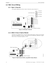
... Strobes Alarm Polarity Shown 24fsclsa.wmf J3 HPF24S Circuit Board Figure 2.4 Style Z (Class A) NACs using ZNAC-4 Option Module 16 HPF24S Series Power Supplies - Alarm Polarity Shown 4.7K ELR Horn Strobe Horn Strobe Horn Strobe 24fsclsb.wmf Figure 2.3 NAC Style Y (Class B) HPF24S Circuit Board... 2.2.2 ZNAC-4 Class A Option Module The ZNAC-4 is Style Y (Class B) as shown in Figure 2.3. This module allows the HPF24S6 or HPF24S8 to connector J3 on the upper right side of the HPF24S circuit board. P/N 52751:F2 7/11/2014 Installation 2.2 NAC Circuit Wiring...
... Strobes Alarm Polarity Shown 24fsclsa.wmf J3 HPF24S Circuit Board Figure 2.4 Style Z (Class A) NACs using ZNAC-4 Option Module 16 HPF24S Series Power Supplies - Alarm Polarity Shown 4.7K ELR Horn Strobe Horn Strobe Horn Strobe 24fsclsb.wmf Figure 2.3 NAC Style Y (Class B) HPF24S Circuit Board... 2.2.2 ZNAC-4 Class A Option Module The ZNAC-4 is Style Y (Class B) as shown in Figure 2.3. This module allows the HPF24S6 or HPF24S8 to connector J3 on the upper right side of the HPF24S circuit board. P/N 52751:F2 7/11/2014 Installation 2.2 NAC Circuit Wiring...

Installation Manual
Page 17
... corner screws. 2. Remove HPF24S main circuit board from the HPF24S Auxiliary Power output directly to male ends of an addressable control, relay or monitor module on the power supply main circuit board. standoff standoff standoff standoff 24fsmodltpH.wmf Module Installation 1. ...female standoffs female/female standoffs mounting screw addressable module Figure 2.5 Mounting Module In HPF-24S Cabinet 24fsmodinstl.wmf HPF24S Series Power Supplies - Place addressable module over standoffs installed in Step 3 and secure with the module status LED visible through bottom ...
... corner screws. 2. Remove HPF24S main circuit board from the HPF24S Auxiliary Power output directly to male ends of an addressable control, relay or monitor module on the power supply main circuit board. standoff standoff standoff standoff 24fsmodltpH.wmf Module Installation 1. ...female standoffs female/female standoffs mounting screw addressable module Figure 2.5 Mounting Module In HPF-24S Cabinet 24fsmodinstl.wmf HPF24S Series Power Supplies - Place addressable module over standoffs installed in Step 3 and secure with the module status LED visible through bottom ...

Installation Manual
Page 18
... nonpower-limited circuit wiring must enter and exit the cabinet through different conduits. Your specific application may be used . Figure 2.5 Power-limited (Class 2) Wiring Example 24fspwrltpH.wmf 18 HPF24S Series Power Supplies - All power-limited (Class 2) circuit wiring must remain at least 0.25" away from any nonpower-limited circuit wiring. One such example of...
... nonpower-limited circuit wiring must enter and exit the cabinet through different conduits. Your specific application may be used . Figure 2.5 Power-limited (Class 2) Wiring Example 24fspwrltpH.wmf 18 HPF24S Series Power Supplies - All power-limited (Class 2) circuit wiring must remain at least 0.25" away from any nonpower-limited circuit wiring. One such example of...

Installation Manual
Page 20
... to the following illustration for switch location and DIP switch placement in ON (Closed) position Figure 3.1 Field Programming DIP Switches 24fsswitc.wmf 20 HPF24S Series Power Supplies - P/N 52751:F2 7/11/2014 The HPF24S can be field programmed using option DIP switch SW1 which is removed. Section 3: Programming Options This section ...describes the programming options available via DIP switch settings. Important: Change DIP switch settings only when all power (AC & DC) is located in the lower center of the circuit board.
... to the following illustration for switch location and DIP switch placement in ON (Closed) position Figure 3.1 Field Programming DIP Switches 24fsswitc.wmf 20 HPF24S Series Power Supplies - P/N 52751:F2 7/11/2014 The HPF24S can be field programmed using option DIP switch SW1 which is removed. Section 3: Programming Options This section ...describes the programming options available via DIP switch settings. Important: Change DIP switch settings only when all power (AC & DC) is located in the lower center of the circuit board.

Installation Manual
Page 21
... (switch 8 ON), Output 4 does not function as Master (switch 3 OFF), NAC Outputs 1 through 42 are controlled by Control Input #1; HPF24S Series Power Supplies - default 1 OFF, 2 ON = System Sensor 1 ON, 2 OFF = Gentex 1 ON, 2 ON = Wheelock FCPS configured for Slave Synchronization FCPS... Output functions 5 OFF, 6 OFF = General Alarm - default Table 3.1 DIP Switch Settings 1 Strobe Synchronization only works with power supply configured for all troubles Internal Trouble contact responds to all outputs will generate a Temporal code signal without turning off the strobe....
... (switch 8 ON), Output 4 does not function as Master (switch 3 OFF), NAC Outputs 1 through 42 are controlled by Control Input #1; HPF24S Series Power Supplies - default 1 OFF, 2 ON = System Sensor 1 ON, 2 OFF = Gentex 1 ON, 2 ON = Wheelock FCPS configured for Slave Synchronization FCPS... Output functions 5 OFF, 6 OFF = General Alarm - default Table 3.1 DIP Switch Settings 1 Strobe Synchronization only works with power supply configured for all troubles Internal Trouble contact responds to all outputs will generate a Temporal code signal without turning off the strobe....
Installation Manual
Page 22
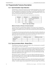
... operation, there is the originator of strobes that is particularly critical when activating strobes which are used . Strobes accomplish this power supply is a feature that controls the activation of notification appliances in the system for Master mode. This maintains the overall system ... The pulses originate from an upstream FACP or other power supply. Make sure that the circuit maximum is selectable via DIP switches 1 and 2. In some installations, it is not exceeded: Strobe Manufacturer System Sensor Wheelock Gentex HPF24S6 (max. Note that all strobes in such a way...
... operation, there is the originator of strobes that is particularly critical when activating strobes which are used . Strobes accomplish this power supply is a feature that controls the activation of notification appliances in the system for Master mode. This maintains the overall system ... The pulses originate from an upstream FACP or other power supply. Make sure that the circuit maximum is selectable via DIP switches 1 and 2. In some installations, it is not exceeded: Strobe Manufacturer System Sensor Wheelock Gentex HPF24S6 (max. Note that all strobes in such a way...

Installation Manual
Page 23
...as a resettable output, the circuit connected to occur). P/N 52751:F2 7/11/2014 23 After this configuration, the Sync Input circuit is ignored if the power supply is set as Slave (switch 3 ON), NAC Outputs 1 through 41 are controlled by Control Input #1; In addition, the Aux. Sync Input is ...but will turn the NACs on steady until the Input becomes inactive. 3.2.3 AC Fail Delay/Aux. In this three second period, the power supply will delay the generation of internal NAC trouble relay in the event that Selective Silence is set to the OFF position will occur (must...
...as a resettable output, the circuit connected to occur). P/N 52751:F2 7/11/2014 23 After this configuration, the Sync Input circuit is ignored if the power supply is set as Slave (switch 3 ON), NAC Outputs 1 through 41 are controlled by Control Input #1; In addition, the Aux. Sync Input is ...but will turn the NACs on steady until the Input becomes inactive. 3.2.3 AC Fail Delay/Aux. In this three second period, the power supply will delay the generation of internal NAC trouble relay in the event that Selective Silence is set to the OFF position will occur (must...