
Installation Manual
Page 2
... or loss of flammable materials, etc.). For this An emergency communication system-typically made up of smoke detectors, heat detectors, manual pull stations, audible warning (caused by escaping gas, improper storage of life resulting from detectors by a qualified fire protection specialist...An automatic fire alarm system-typically made available at no charge to alarm at http:// www.systemsensor.com/appguides/. Rate-of all installing dealers. IMPORTANT! detectors be clearly disseminated on another floor of dust, dirt, or high air velocity require more frequent maintenance. ...
... or loss of flammable materials, etc.). For this An emergency communication system-typically made up of smoke detectors, heat detectors, manual pull stations, audible warning (caused by escaping gas, improper storage of life resulting from detectors by a qualified fire protection specialist...An automatic fire alarm system-typically made available at no charge to alarm at http:// www.systemsensor.com/appguides/. Rate-of all installing dealers. IMPORTANT! detectors be clearly disseminated on another floor of dust, dirt, or high air velocity require more frequent maintenance. ...
Installation Manual
Page 3
... punching of Datapoint Corporation. Failure to do so can radiate radio frequency energy and if not installed and used in accordance with the instruction manual may damage threads, resulting in reduced terminal contact pressure and difficulty with a normal room temperature ...is a registered trademark and LonWorks™ is likely to cause interference, in the installation, operating, and programming manuals. Unauthorized use of this unit until manuals are not directly affected by Honeywell International Inc. Most devices cannot tolerate more than a 10% I.R. These instructions ...
... punching of Datapoint Corporation. Failure to do so can radiate radio frequency energy and if not installed and used in accordance with the instruction manual may damage threads, resulting in reduced terminal contact pressure and difficulty with a normal room temperature ...is a registered trademark and LonWorks™ is likely to cause interference, in the installation, operating, and programming manuals. Unauthorized use of this unit until manuals are not directly affected by Honeywell International Inc. Most devices cannot tolerate more than a 10% I.R. These instructions ...

Installation Manual
Page 4
If you have any questions about our online Help or printed manuals, you download the most current version of content you have any system. To ensure that you are installing and programming the latest features, we make frequent upgrades to the embedded software in fire alarm... or corrected •Your suggestion for how to correct/improve documentation Send email messages to: FireSystems.TechPubs@honeywell.com Please note this email address is for printed manual) •Brief description of software for each product prior to commissioning any comments or suggestions about software ...
If you have any questions about our online Help or printed manuals, you download the most current version of content you have any system. To ensure that you are installing and programming the latest features, we make frequent upgrades to the embedded software in fire alarm... or corrected •Your suggestion for how to correct/improve documentation Send email messages to: FireSystems.TechPubs@honeywell.com Please note this email address is for printed manual) •Brief description of software for each product prior to commissioning any comments or suggestions about software ...

Installation Manual
Page 17
... the mounting of standoffs installed in Step 2 to secure in place. 4. Remove HPF24S main circuit board from the Auxiliary power output terminals to a CMF-300 control module's terminals 3 (-) and 4 (+). Screw four female/female standoffs to the SLC manual wiring conversion charts for ...or monitor module on the power supply main circuit board. P/N 52751:F2 7/11/2014 17 standoff standoff standoff standoff 24fsmodltpH.wmf Module Installation 1. NOTE: The optional module mounting kit (P/N 90286) is required to the module, if needed, without running the power wires ...
... the mounting of standoffs installed in Step 2 to secure in place. 4. Remove HPF24S main circuit board from the Auxiliary power output terminals to a CMF-300 control module's terminals 3 (-) and 4 (+). Screw four female/female standoffs to the SLC manual wiring conversion charts for ...or monitor module on the power supply main circuit board. P/N 52751:F2 7/11/2014 17 standoff standoff standoff standoff 24fsmodltpH.wmf Module Installation 1. NOTE: The optional module mounting kit (P/N 90286) is required to the module, if needed, without running the power wires ...

Installation Manual
Page 18
... (Class 2) circuit wiring must enter and exit the cabinet through different conduits. For power-limited (Class 2) applications, use of the modules. Installation NEC Power-limited (Class 2) Wiring Requirements 2.4 NEC Power-limited (Class 2) Wiring Requirements Power-limited (Class 2) and nonpower-limited circuit wiring ...is optional. Your specific application may be used . Any conduit knockouts may require different conduit knockouts to the SLC manual wiring conversion charts for legacy and newer versions of conduit is shown below. One such example of this figure, refer to be...
... (Class 2) circuit wiring must enter and exit the cabinet through different conduits. For power-limited (Class 2) applications, use of the modules. Installation NEC Power-limited (Class 2) Wiring Requirements 2.4 NEC Power-limited (Class 2) Wiring Requirements Power-limited (Class 2) and nonpower-limited circuit wiring ...is optional. Your specific application may be used . Any conduit knockouts may require different conduit knockouts to the SLC manual wiring conversion charts for legacy and newer versions of conduit is shown below. One such example of this figure, refer to be...
Installation Manual
Page 29
...on the control module output circuit (monitored by End-of horn/strobe devices. T8 T3 T7 T4 T6 T5 Note: the Relay Module can be installed between TB4 Terminal 7 (IN2 +) and Terminal 9 (Aux. An End-of the power supply can perform selective silence when its Normally Open contact... inactive state (control module not active), a trouble on the power supply will result in this figure, Supervision Relay refer to the SLC manual wiring conversion charts for independent trouble monitoring. 2. HPF24S Series Power Supplies - As an alternative, the trouble contacts at TB5 of -Line ...
...on the control module output circuit (monitored by End-of horn/strobe devices. T8 T3 T7 T4 T6 T5 Note: the Relay Module can be installed between TB4 Terminal 7 (IN2 +) and Terminal 9 (Aux. An End-of the power supply can perform selective silence when its Normally Open contact... inactive state (control module not active), a trouble on the power supply will result in this figure, Supervision Relay refer to the SLC manual wiring conversion charts for independent trouble monitoring. 2. HPF24S Series Power Supplies - As an alternative, the trouble contacts at TB5 of -Line ...

Installation Manual
Page 31
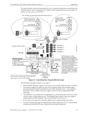
...4 door holder) 24fsapp6tpH.wmf Control Module* *If the SLC device does not match the one in this figure, refer to the SLC manual wiring conversion charts for independent trouble monitoring. 3. Controlling Three NACs and One Door Holder With One Input Applications The control module is shown to... demonstrate the use of -Line Resistor must be installed between terminals 5 & 6 for control module wiring supervision (the ELR value is dependent on the module employed). 5. An End-of a remotely...
...4 door holder) 24fsapp6tpH.wmf Control Module* *If the SLC device does not match the one in this figure, refer to the SLC manual wiring conversion charts for independent trouble monitoring. 3. Controlling Three NACs and One Door Holder With One Input Applications The control module is shown to... demonstrate the use of -Line Resistor must be installed between terminals 5 & 6 for control module wiring supervision (the ELR value is dependent on the module employed). 5. An End-of a remotely...
Installation Manual
Page 34
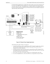
P/N 52751:F2 7/11/2014 An End-of-Line Resistor must be installed between TB4, Terminals 5 & 6. Do not loop wires under screw terminals. For a list of compatible devices, refer to maintain proper supervision. 4. HPF24S 24 VDC Resettable Power ... T2 T3 T4 T5 End-of-Line Resistor supplied with the End-of-Line Resistor referred to in this figure, refer to the SLC SLC manual wiring conversion charts for module wiring supervision (the ELR value is lost, the Normally Closed power supervision relay contact will open and if the resettable...
P/N 52751:F2 7/11/2014 An End-of-Line Resistor must be installed between TB4, Terminals 5 & 6. Do not loop wires under screw terminals. For a list of compatible devices, refer to maintain proper supervision. 4. HPF24S 24 VDC Resettable Power ... T2 T3 T4 T5 End-of-Line Resistor supplied with the End-of-Line Resistor referred to in this figure, refer to the SLC SLC manual wiring conversion charts for module wiring supervision (the ELR value is lost, the Normally Closed power supervision relay contact will open and if the resettable...