User Manual
Page 3
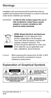
... performed only by qualified and experienced technicians to conform to all local codes and to ensure compliance with separate collection systems). Caution When powering the camera from 24 VAC, a UPS source should be disposed of, at the end of CSA Certified/UL Listed Class 2 power adapters to maintain your warranty. Correct...
... performed only by qualified and experienced technicians to conform to all local codes and to ensure compliance with separate collection systems). Caution When powering the camera from 24 VAC, a UPS source should be disposed of, at the end of CSA Certified/UL Listed Class 2 power adapters to maintain your warranty. Correct...
User Manual
Page 5
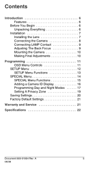
Contents Introduction 6 Features 6 Before You Begin 6 Unpacking Everything 6 Installation 7 Installing the Lens 7 Connecting the Camera 8 Connecting LAMP Contact 9 Adjusting The Back Focus 9 Mounting the Camera 10 Making Final Adjustments 10 Programming 11 OSD Menu Controls 11 SETUP Menu 12 SETUP Menu Functions 13 SPECIAL Menu 14 SPECIAL Menu Functions 15 Adding a Camera ID Display 16 Programming Day and Night Modes 17 Setting A Privacy Zone 19 Saving Settings 20 Factory Default Settings 21 Warranty and Service 21 Specifications 22 Document 800-01954 Rev A 5 08/08
Contents Introduction 6 Features 6 Before You Begin 6 Unpacking Everything 6 Installation 7 Installing the Lens 7 Connecting the Camera 8 Connecting LAMP Contact 9 Adjusting The Back Focus 9 Mounting the Camera 10 Making Final Adjustments 10 Programming 11 OSD Menu Controls 11 SETUP Menu 12 SETUP Menu Functions 13 SPECIAL Menu 14 SPECIAL Menu Functions 15 Adding a Camera ID Display 16 Programming Day and Night Modes 17 Setting A Privacy Zone 19 Saving Settings 20 Factory Default Settings 21 Warranty and Service 21 Specifications 22 Document 800-01954 Rev A 5 08/08
User Manual
Page 6
... Check that the items received match those listed on the order form and packing slip. Introduction The Honeywell HCD544 Day/Night Color Camera (HCD544) is designed for general surveillance applications and is ideally suited for contact information). The HCD544 packing box should include, in low-light conditions • Minimum illumination of this guide carefully before...
... Check that the items received match those listed on the order form and packing slip. Introduction The Honeywell HCD544 Day/Night Color Camera (HCD544) is designed for general surveillance applications and is ideally suited for contact information). The HCD544 packing box should include, in low-light conditions • Minimum illumination of this guide carefully before...
User Manual
Page 7
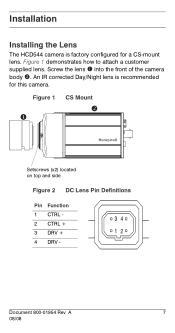
Installation Installing the Lens The HCD544 camera is recommended for a CS-mount lens. Screw the lens ! CS Mount " Setscrews (x2) located on top and side Figure 2 DC Lens Pin Definitions Pin Function 1 CTRL - 34 2 CTRL + 3 DRV + 12 4 DRV - Document 800-01954 Rev A 7 08/08 Figure 1 demonstrates how to attach a customer supplied lens. An IR corrected Day/Night lens is factory configured for this camera. Figure 1 ! into the front of the camera body ".
Installation Installing the Lens The HCD544 camera is recommended for a CS-mount lens. Screw the lens ! CS Mount " Setscrews (x2) located on top and side Figure 2 DC Lens Pin Definitions Pin Function 1 CTRL - 34 2 CTRL + 3 DRV + 12 4 DRV - Document 800-01954 Rev A 7 08/08 Figure 1 demonstrates how to attach a customer supplied lens. An IR corrected Day/Night lens is factory configured for this camera. Figure 1 ! into the front of the camera body ".
User Manual
Page 8
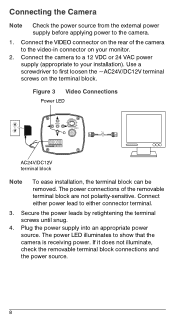
... To ease installation, the terminal block can be removed. Use a screwdriver to the video-in connector on your installation). Connecting the Camera Note Check the power source from the external power supply before applying power to either connector terminal. 3. If it does not illuminate,...the removable terminal block connections and the power source. 8 Connect either power lead to the camera. 1. Connect the camera to a 12 VDC or 24 VAC power supply (appropriate to show that the camera is receiving power. The power LED illuminates to your monitor. 2. Plug the power supply...
... To ease installation, the terminal block can be removed. Use a screwdriver to the video-in connector on your installation). Connecting the Camera Note Check the power source from the external power supply before applying power to either connector terminal. 3. If it does not illuminate,...the removable terminal block connections and the power source. 8 Connect either power lead to the camera. 1. Connect the camera to a 12 VDC or 24 VAC power supply (appropriate to show that the camera is receiving power. The power LED illuminates to your monitor. 2. Plug the power supply...
User Manual
Page 9
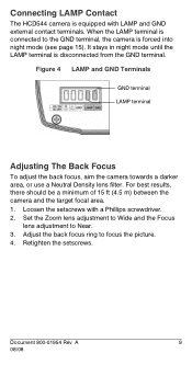
... forced into night mode (see page 15). Document 800-01954 Rev A 9 08/08 Retighten the setscrews. Connecting LAMP Contact The HCD544 camera is equipped with a Phillips screwdriver. 2. Loosen the setscrews with LAMP and GND external contact terminals. Adjust the back focus ring to focus the ...picture. 4. For best results, there should be a minimum of 15 ft (4.5 m) between the camera and the target focal area. 1. Figure 4 LAMP and GND Terminals GND terminal LAMP terminal Adjusting The Back Focus To adjust the back focus, aim the...
... forced into night mode (see page 15). Document 800-01954 Rev A 9 08/08 Retighten the setscrews. Connecting LAMP Contact The HCD544 camera is equipped with a Phillips screwdriver. 2. Loosen the setscrews with LAMP and GND external contact terminals. Adjust the back focus ring to focus the ...picture. 4. For best results, there should be a minimum of 15 ft (4.5 m) between the camera and the target focal area. 1. Figure 4 LAMP and GND Terminals GND terminal LAMP terminal Adjusting The Back Focus To adjust the back focus, aim the...
User Manual
Page 10
... 13). Confirm the exposure on the monitor screen. 10 They are used to mount the camera on a bracket or tripod. The mounting bracket must be capable of supporting the weight of the camera and its lens. Making Final Adjustments Adjust the focus for your desired field of view; that... mounting bracket must be capable of supporting up to four times the combined weight of the camera and lens. Mounting the Camera Mounting points are provided on the top and bottom of the camera and are designed to accept standard sized mounting bolts. If necessary, adjust the brightness using the...
... 13). Confirm the exposure on the monitor screen. 10 They are used to mount the camera on a bracket or tripod. The mounting bracket must be capable of supporting the weight of the camera and its lens. Making Final Adjustments Adjust the focus for your desired field of view; that... mounting bracket must be capable of supporting up to four times the combined weight of the camera and lens. Mounting the Camera Mounting points are provided on the top and bottom of the camera and are designed to accept standard sized mounting bolts. If necessary, adjust the brightness using the...
User Manual
Page 11
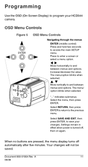
... minutes. ".." Select SAVE AND EXIT, then press ENTER, to and between menus and options. The menu/option blinks when selected. #, $ Move vertically to save your HCD544 camera. indicates submenus. The menu/ option blinks when selected. Press to enter a screen or select a menu option. !, " Move horizontally to access the main SETUP menu. OSD...
... minutes. ".." Select SAVE AND EXIT, then press ENTER, to and between menus and options. The menu/option blinks when selected. #, $ Move vertically to save your HCD544 camera. indicates submenus. The menu/ option blinks when selected. Press to enter a screen or select a menu option. !, " Move horizontally to access the main SETUP menu. OSD...
User Manual
Page 12
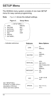
... 13 for easy camera programming. MANUAL .. ON OFF 18 dB~30 dB OFF See SPECIAL Menu. 12 Note Figure 6 shows the default settings. Figure 6 Setup Menu 1 LENS MANUAL 2 SHUTTER ESC .. 3 WHITE BAL AWC .. 4 BACKLIGHT OFF 5 AGC 30dB 6 SPECIAL .. 7 EXIT MENU .. .. ESC .. AWC PUSH/LOCK USER .. SETUP Menu The HCD544 menu system consists...
... 13 for easy camera programming. MANUAL .. ON OFF 18 dB~30 dB OFF See SPECIAL Menu. 12 Note Figure 6 shows the default settings. Figure 6 Setup Menu 1 LENS MANUAL 2 SHUTTER ESC .. 3 WHITE BAL AWC .. 4 BACKLIGHT OFF 5 AGC 30dB 6 SPECIAL .. 7 EXIT MENU .. .. ESC .. AWC PUSH/LOCK USER .. SETUP Menu The HCD544 menu system consists...
User Manual
Page 14
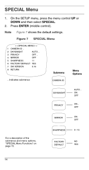
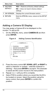
... (middle control). OFF MIRROR ON OFF For a description of the submenus and menu options, "SPECIAL Menu Functions" on page 15. SPECIAL Menu 1. Figure 7 SPECIAL Menu 1 CAMERA ID .. 2 DAY&NIGHT AUTO .. 3 PRIVACY OFF .. 4 MIRROR OFF 5 SHARPNESS 11 6 FACTORY DEFAULT YES 7 SW VERSION 0.16 8 RETURN .. On the SETUP menu, press the menu control...
... (middle control). OFF MIRROR ON OFF For a description of the submenus and menu options, "SPECIAL Menu Functions" on page 15. SPECIAL Menu 1. Figure 7 SPECIAL Menu 1 CAMERA ID .. 2 DAY&NIGHT AUTO .. 3 PRIVACY OFF .. 4 MIRROR OFF 5 SHARPNESS 11 6 FACTORY DEFAULT YES 7 SW VERSION 0.16 8 RETURN .. On the SETUP menu, press the menu control...
User Manual
Page 15
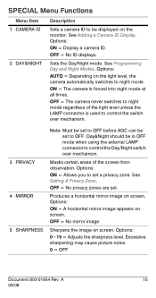
... may cause picture noise. 0 = OFF Document 800-01954 Rev A 15 08/08 OFF = No privacy zones are set to night mode. OFF = The camera never switches to night mode regardless of the screen from observation. OFF = No mirror image Sharpens the image on screen. Options: ON = Display... the light level unless the LAMP connector is forced into night mode at all times. Produces a horizontal mirror image on the monitor. See Adding a Camera ID Display. Day&Night should be in OFF mode when using the external LAMP connector to set a privacy zone. Options: ON = Allows you to...
... may cause picture noise. 0 = OFF Document 800-01954 Rev A 15 08/08 OFF = No privacy zones are set to night mode. OFF = The camera never switches to night mode regardless of the screen from observation. OFF = No mirror image Sharpens the image on screen. Options: ON = Display... the light level unless the LAMP connector is forced into night mode at all times. Produces a horizontal mirror image on the monitor. See Adding a Camera ID Display. Day&Night should be in OFF mode when using the external LAMP connector to set a privacy zone. Options: ON = Allows you to...
User Manual
Page 16
... to confirm the position. 16 then press ENTER to be displayed on screen. On the SPECIAL menu, select CAMERA ID and then press ENTER. Figure 8 Adding Camera Identification 1 POSITION R.BOT a ABCDEFGHIJKLMNOPQRST b UVWXYZabcdefghijklmn c opqrstuvwxyz12345678 d 9 2 ID: RETURN 2. Displays the current... firmware version Exits the SPECIAL menu; returns to the SETUP menu Adding a Camera ID Display You may assign a Camera ID to be located on the monitor. Select POS to position where you would like the ID to accept it. ...
... to confirm the position. 16 then press ENTER to be displayed on screen. On the SPECIAL menu, select CAMERA ID and then press ENTER. Figure 8 Adding Camera Identification 1 POSITION R.BOT a ABCDEFGHIJKLMNOPQRST b UVWXYZabcdefghijklmn c opqrstuvwxyz12345678 d 9 2 ID: RETURN 2. Displays the current... firmware version Exits the SPECIAL menu; returns to the SETUP menu Adding a Camera ID Display You may assign a Camera ID to be located on the monitor. Select POS to position where you would like the ID to accept it. ...
User Manual
Page 17
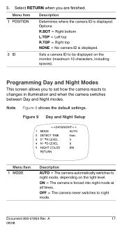
...Note Figure 9 shows the default settings. Programming Day and Night Modes This screen allows you are finished. ON = The camera is displayed. 2 ID Sets a camera ID to night mode, depending on the monitor (maximum 10 characters, including spaces). Document 800-01954 Rev A 17 08/... 5 8 5 NIGHT COLOR BW RETURN Menu Item 1 MODE Description AUTO = The camera automatically switches to be displayed on the light level. OFF = The camera never switches to changes in illumination and when the camera switches between Day and Night modes. 5. Select RETURN when you to set how the...
...Note Figure 9 shows the default settings. Programming Day and Night Modes This screen allows you are finished. ON = The camera is displayed. 2 ID Sets a camera ID to night mode, depending on the monitor (maximum 10 characters, including spaces). Document 800-01954 Rev A 17 08/... 5 8 5 NIGHT COLOR BW RETURN Menu Item 1 MODE Description AUTO = The camera automatically switches to be displayed on the light level. OFF = The camera never switches to changes in illumination and when the camera switches between Day and Night modes. 5. Select RETURN when you to set how the...
User Manual
Page 18
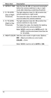
...;D LEVEL. 5 NIGHT COLOR Sets the color mode in 5-second increments) before the camera switches to day or night mode after detecting a switching threshold. The light detection level (4~15) at which the camera switches to day mode. The lower the value, the darker the lighting must be before... the camera switches. The higher the value, the brighter the lighting must be before the camera switches. The light detection level (1~12) at which the camera switches to night mode. Menu Item Description 2 DETECT TIME 3 D➝N...
...;D LEVEL. 5 NIGHT COLOR Sets the color mode in 5-second increments) before the camera switches to day or night mode after detecting a switching threshold. The light detection level (4~15) at which the camera switches to day mode. The lower the value, the darker the lighting must be before... the camera switches. The higher the value, the brighter the lighting must be before the camera switches. The light detection level (1~12) at which the camera switches to night mode. Menu Item Description 2 DETECT TIME 3 D➝N...
User Manual
Page 19
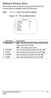
... end position, from this area. that is set. Setting A Privacy Zone Set an area of the scene from viewing OFF = No privacy zone is , the camera does not display video from 0~122 Document 800-01954 Rev A 19 08/08 Figure 10 Privacy Mode Setup 1 CONTROL OFF 2 H START 0 3 H END 0 4 V START 0 5 V END 0 RETURN...
... end position, from this area. that is set. Setting A Privacy Zone Set an area of the scene from viewing OFF = No privacy zone is , the camera does not display video from 0~122 Document 800-01954 Rev A 19 08/08 Figure 10 Privacy Mode Setup 1 CONTROL OFF 2 H START 0 3 H END 0 4 V START 0 5 V END 0 RETURN...
User Manual
Page 20
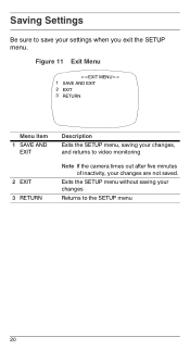
Exits the SETUP menu without saving your changes Returns to save your changes are not saved. Saving Settings Be sure to the SETUP menu 20 Figure 11 Exit Menu 1 SAVE AND EXIT 2 EXIT 3 RETURN Menu Item 1 SAVE AND EXIT 2 EXIT 3 RETURN Description Exits the SETUP menu, saving your changes, and returns to video monitoring Note If the camera times out after five minutes of inactivity, your settings when you exit the SETUP menu.
Exits the SETUP menu without saving your changes Returns to save your changes are not saved. Saving Settings Be sure to the SETUP menu 20 Figure 11 Exit Menu 1 SAVE AND EXIT 2 EXIT 3 RETURN Menu Item 1 SAVE AND EXIT 2 EXIT 3 RETURN Description Exits the SETUP menu, saving your changes, and returns to video monitoring Note If the camera times out after five minutes of inactivity, your settings when you exit the SETUP menu.

User Manual
Page 22
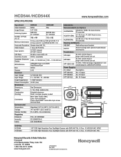
...: S/N Ratio: Auto Gain Control: Automatic Electronic Shutter: White Balance: BLC: Gamma: Electrical Input Voltage: Input Range: Surge Suppression: Power Consumption: Mechanical Dimensions: Weight: Construction: (housing) HCD544 (NTSC) HCD544X (PAL) 1/3" CCD NTSC PAL 525 lines, 2:1 interlace 625/50 lines, 2:1 interlace 768 x 494 752 x 582 0.5 lux color/0.25 lux B/W @ 50 IRE, f1.2 0.3 ...Lock/AWC Auto/ Manual/User Off/On 0.45 12 VDC/24 VAC 11-16 VDC, 17-28 VAC 1.5 kW transient 4.5 W (max) See Dimensions 1.1 lb (.5 kg), camera only Extruded aluminum Finish: cool gray powder coated 22
...: S/N Ratio: Auto Gain Control: Automatic Electronic Shutter: White Balance: BLC: Gamma: Electrical Input Voltage: Input Range: Surge Suppression: Power Consumption: Mechanical Dimensions: Weight: Construction: (housing) HCD544 (NTSC) HCD544X (PAL) 1/3" CCD NTSC PAL 525 lines, 2:1 interlace 625/50 lines, 2:1 interlace 768 x 494 752 x 582 0.5 lux color/0.25 lux B/W @ 50 IRE, f1.2 0.3 ...Lock/AWC Auto/ Manual/User Off/On 0.45 12 VDC/24 VAC 11-16 VDC, 17-28 VAC 1.5 kW transient 4.5 W (max) See Dimensions 1.1 lb (.5 kg), camera only Extruded aluminum Finish: cool gray powder coated 22
Brochure
Page 1
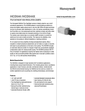
...shutter for changes in retail, financial, and other commercial markets. The HCD544 produces 540 TV lines of resolution for applications requiring the highest level of the camera. The camera uses internal logic or an external LAMP connector to control the switchover from...performance down to capture more detail using the increased sensitivity of the camera in very low light. HCD544 /HCD544X TRUE DAY/NIGHT HIGH RESOLUTION CAMERA www.honeywellvideo.com The Honeywell HCD544 True Day/Night camera is designed for high resolution 24/7 surveillance applications, including those using ...
...shutter for changes in retail, financial, and other commercial markets. The HCD544 produces 540 TV lines of resolution for applications requiring the highest level of the camera. The camera uses internal logic or an external LAMP connector to control the switchover from...performance down to capture more detail using the increased sensitivity of the camera in very low light. HCD544 /HCD544X TRUE DAY/NIGHT HIGH RESOLUTION CAMERA www.honeywellvideo.com The Honeywell HCD544 True Day/Night camera is designed for high resolution 24/7 surveillance applications, including those using ...
Brochure
Page 2
... GND LAMP GND .49" (12.5 mm) Ordering HCD544 HCD544X 1/3" CCD High Resolution True Day/Night Camera with DSP, 540 TVL, 0.3 lux, 12 VDC/24 VAC, NTSC 1/3" CCD High Resolution True Day/Night Camera with DSP, 540 TVL, 0.3 lux, 12 VDC/24 VAC, PAL Honeywell Security & Data Collection Honeywell 2700 Blankenbaker Pkwy, Suite 150 Louisville, KY...
... GND LAMP GND .49" (12.5 mm) Ordering HCD544 HCD544X 1/3" CCD High Resolution True Day/Night Camera with DSP, 540 TVL, 0.3 lux, 12 VDC/24 VAC, NTSC 1/3" CCD High Resolution True Day/Night Camera with DSP, 540 TVL, 0.3 lux, 12 VDC/24 VAC, PAL Honeywell Security & Data Collection Honeywell 2700 Blankenbaker Pkwy, Suite 150 Louisville, KY...

