
User Manual
Page 2
... with the manufacturer's instructions. • Do not install near water. • Clean only with the apparatus. • Refer all servicing to qualified service personnel. 2 Revisions Issue A Date 08/08 Revisions New document Important Safety Information • Read and keep these instructions. • Heed all warnings. • Follow all instructions. • Do not use this apparatus near any heat...
... with the manufacturer's instructions. • Do not install near water. • Clean only with the apparatus. • Refer all servicing to qualified service personnel. 2 Revisions Issue A Date 08/08 Revisions New document Important Safety Information • Read and keep these instructions. • Heed all warnings. • Follow all instructions. • Do not use this apparatus near any heat...
User Manual
Page 3
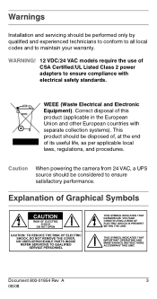
... Listed Class 2 power adapters to ensure compliance with separate collection systems). This product should be considered to maintain your warranty. WEEE (Waste Electrical and Electronic Equipment). Warnings Installation and servicing should be performed only by qualified and experienced technicians to conform to all local codes and to ensure satisfactory performance. Caution When powering the camera from 24...
... Listed Class 2 power adapters to ensure compliance with separate collection systems). This product should be considered to maintain your warranty. WEEE (Waste Electrical and Electronic Equipment). Warnings Installation and servicing should be performed only by qualified and experienced technicians to conform to all local codes and to ensure satisfactory performance. Caution When powering the camera from 24...

User Manual
Page 4
...supplied with this equipment does cause harmful interference to radio or television reception, which can radiate radio frequency energy and, if not installed and used in a particular installation... Caution Changes or ...digital device, pursuant to operate the equipment. This equipment generates, uses, and can be determined by turning the equipment off and on a circuit different from that interference will not occur in accordance with the instructions, may cause harmful interference to which the receiver is connected. • Consult the dealer or a radio/TV technician for help...
...supplied with this equipment does cause harmful interference to radio or television reception, which can radiate radio frequency energy and, if not installed and used in a particular installation... Caution Changes or ...digital device, pursuant to operate the equipment. This equipment generates, uses, and can be determined by turning the equipment off and on a circuit different from that interference will not occur in accordance with the instructions, may cause harmful interference to which the receiver is connected. • Consult the dealer or a radio/TV technician for help...
User Manual
Page 5
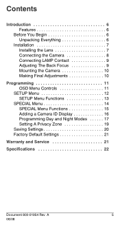
Contents Introduction 6 Features 6 Before You Begin 6 Unpacking Everything 6 Installation 7 Installing the Lens 7 Connecting the Camera 8 Connecting LAMP Contact 9 Adjusting The Back Focus 9 Mounting the Camera 10 Making Final Adjustments 10 Programming 11 OSD Menu Controls 11 SETUP Menu 12 SETUP Menu Functions 13 SPECIAL Menu 14 SPECIAL Menu Functions 15 Adding a Camera ID Display 16 Programming Day and Night Modes 17 Setting A Privacy Zone 19 Saving Settings 20 Factory Default Settings 21 Warranty and Service 21 Specifications 22 Document 800-01954 Rev A 5 08/08
Contents Introduction 6 Features 6 Before You Begin 6 Unpacking Everything 6 Installation 7 Installing the Lens 7 Connecting the Camera 8 Connecting LAMP Contact 9 Adjusting The Back Focus 9 Mounting the Camera 10 Making Final Adjustments 10 Programming 11 OSD Menu Controls 11 SETUP Menu 12 SETUP Menu Functions 13 SPECIAL Menu 14 SPECIAL Menu Functions 15 Adding a Camera ID Display 16 Programming Day and Night Modes 17 Setting A Privacy Zone 19 Saving Settings 20 Factory Default Settings 21 Warranty and Service 21 Specifications 22 Document 800-01954 Rev A 5 08/08
User Manual
Page 6
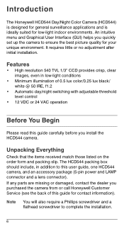
...; Minimum illumination of 0.5 lux color/0.25 lux black/ white @ 50 IRE, f1.2 • Automatic day/night switching with adjustable threshold level control • 12 VDC or 24 VAC operation Before You Begin Please read this guide carefully before you purchased the camera from or call Honeywell Customer Service (see the back of this user guide, one HCD544 camera, and an accessory package (5-pin power and LAMP connector and a lens connector).
...; Minimum illumination of 0.5 lux color/0.25 lux black/ white @ 50 IRE, f1.2 • Automatic day/night switching with adjustable threshold level control • 12 VDC or 24 VAC operation Before You Begin Please read this guide carefully before you purchased the camera from or call Honeywell Customer Service (see the back of this user guide, one HCD544 camera, and an accessory package (5-pin power and LAMP connector and a lens connector).
User Manual
Page 7
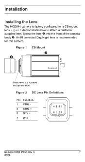
into the front of the camera body ". Figure 1 ! Screw the lens ! An IR corrected Day/Night lens is factory configured for this camera. CS Mount " Setscrews (x2) located on top and side Figure 2 DC Lens Pin Definitions Pin Function 1 CTRL - 34 2 CTRL + 3 DRV + 12 4 DRV - Document 800-01954 Rev A 7 08/08 Figure 1 demonstrates how to attach a customer supplied lens. Installation Installing the Lens The HCD544 camera is recommended for a CS-mount lens.
into the front of the camera body ". Figure 1 ! Screw the lens ! An IR corrected Day/Night lens is factory configured for this camera. CS Mount " Setscrews (x2) located on top and side Figure 2 DC Lens Pin Definitions Pin Function 1 CTRL - 34 2 CTRL + 3 DRV + 12 4 DRV - Document 800-01954 Rev A 7 08/08 Figure 1 demonstrates how to attach a customer supplied lens. Installation Installing the Lens The HCD544 camera is recommended for a CS-mount lens.
User Manual
Page 8
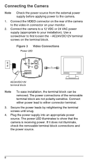
... camera is receiving power. The power LED illuminates to either connector terminal. 3. Connect the VIDEO connector on the rear of the removable terminal block are not polarity-sensitive. Secure the power leads by retightening the terminal screws until snug. 4. If it does not illuminate, check the removable terminal block connections and the power source. 8 Plug the power supply into an appropriate power source. Use a screwdriver to the video-in connector...
... camera is receiving power. The power LED illuminates to either connector terminal. 3. Connect the VIDEO connector on the rear of the removable terminal block are not polarity-sensitive. Secure the power leads by retightening the terminal screws until snug. 4. If it does not illuminate, check the removable terminal block connections and the power source. 8 Plug the power supply into an appropriate power source. Use a screwdriver to the video-in connector...
User Manual
Page 9
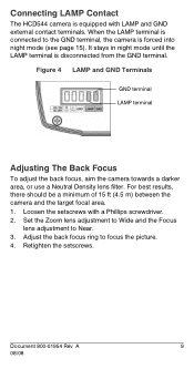
.... 1. Set the Zoom lens adjustment to Wide and the Focus lens adjustment to the GND terminal, the camera is forced into night mode (see page 15). Document 800-01954 Rev A 9 08/08 When the LAMP terminal is connected to Near. 3. Figure 4 LAMP and GND Terminals GND terminal LAMP terminal Adjusting The Back Focus To adjust the back focus, aim the camera towards a darker area, or use a Neutral...
.... 1. Set the Zoom lens adjustment to Wide and the Focus lens adjustment to the GND terminal, the camera is forced into night mode (see page 15). Document 800-01954 Rev A 9 08/08 When the LAMP terminal is connected to Near. 3. Figure 4 LAMP and GND Terminals GND terminal LAMP terminal Adjusting The Back Focus To adjust the back focus, aim the camera towards a darker area, or use a Neutral...
User Manual
Page 10
... Control) on the monitor screen. 10 Confirm the exposure on page 13). Mounting the Camera Mounting points are provided on the top and bottom of the camera and are designed to accept standard sized mounting bolts. The mounting bracket must be capable of supporting the weight of the camera and its lens. If necessary, adjust the brightness using the OSD menu controls (see a clear image. Making Final Adjustments Adjust the focus...
... Control) on the monitor screen. 10 Confirm the exposure on page 13). Mounting the Camera Mounting points are provided on the top and bottom of the camera and are designed to accept standard sized mounting bolts. The mounting bracket must be capable of supporting the weight of the camera and its lens. If necessary, adjust the brightness using the OSD menu controls (see a clear image. Making Final Adjustments Adjust the focus...
User Manual
Page 11
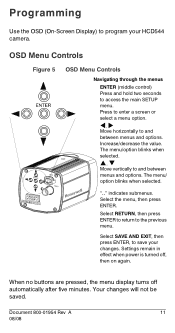
... menu/ option blinks when selected. Settings remain in effect when power is turned off automatically after five minutes. When no buttons are pressed, the menu display turns off , then on again. ".." Select the menu, then press ENTER. Select SAVE AND EXIT, then press ENTER, to save your HCD544 camera. Increase/decrease the value. OSD Menu Controls Figure 5 OSD Menu Controls Navigating through the menus ENTER (middle control...
... menu/ option blinks when selected. Settings remain in effect when power is turned off automatically after five minutes. When no buttons are pressed, the menu display turns off , then on again. ".." Select the menu, then press ENTER. Select SAVE AND EXIT, then press ENTER, to save your HCD544 camera. Increase/decrease the value. OSD Menu Controls Figure 5 OSD Menu Controls Navigating through the menus ENTER (middle control...
User Manual
Page 12
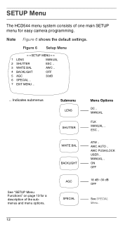
... "SETUP Menu Functions" on page 13 for easy camera programming. MANUAL FLK MANUAL .. ESC .. MANUAL .. Note Figure 6 shows the default settings. AWC AUTO .. Submenu LENS SHUTTER WHITE BAL BACKLIGHT AGC SPECIAL Menu Options DC .. ATW .. AWC PUSH/LOCK USER .. ON OFF 18 dB~30 dB OFF See SPECIAL Menu. 12 SETUP Menu The HCD544 menu system consists of one main SETUP menu for a description of the submenus and menu options. Figure 6 Setup Menu 1 LENS MANUAL 2 SHUTTER...
... "SETUP Menu Functions" on page 13 for easy camera programming. MANUAL FLK MANUAL .. ESC .. MANUAL .. Note Figure 6 shows the default settings. AWC AUTO .. Submenu LENS SHUTTER WHITE BAL BACKLIGHT AGC SPECIAL Menu Options DC .. ATW .. AWC PUSH/LOCK USER .. ON OFF 18 dB~30 dB OFF See SPECIAL Menu. 12 SETUP Menu The HCD544 menu system consists of one main SETUP menu for a description of the submenus and menu options. Figure 6 Setup Menu 1 LENS MANUAL 2 SHUTTER...
User Manual
Page 13
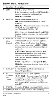
... to video monitoring. MANUAL = Adjusts the shutter speed from 1/601/100,000 of a second (NTSC), or 1/50-1/100,000 of AGC gain. Controls color on -screen flickering. OFF = DAY&NIGHT mode must be OFF to adjust the brightness level. SETUP Menu Functions Menu Item Description 1 LENS Selects Lens type. Press ENTER with DC selected to turn AGC OFF. 6 SPECIAL .. returns to change the mode. AWC AUTO = A faster AWB mode with DC lens. 3 WHITE...
... to video monitoring. MANUAL = Adjusts the shutter speed from 1/601/100,000 of a second (NTSC), or 1/50-1/100,000 of AGC gain. Controls color on -screen flickering. OFF = DAY&NIGHT mode must be OFF to adjust the brightness level. SETUP Menu Functions Menu Item Description 1 LENS Selects Lens type. Press ENTER with DC selected to turn AGC OFF. 6 SPECIAL .. returns to change the mode. AWC AUTO = A faster AWB mode with DC lens. 3 WHITE...
User Manual
Page 14
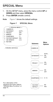
SHARPNESS 0~15 FACTORY NO DEFAULT YES 14 SPECIAL Menu 1. Figure 7 SPECIAL Menu 1 CAMERA ID .. 2 DAY&NIGHT AUTO .. 3 PRIVACY OFF .. 4 MIRROR OFF 5 SHARPNESS 11 6 FACTORY DEFAULT YES 7 SW VERSION 0.16 8 RETURN .. On the SETUP menu, press the menu control UP or DOWN and then select SPECIAL. 2. Press ENTER (middle control). ON OFF ON .. indicates submenus Submenu CAMERA ID Menu Options DAY&NIGHT PRIVACY AUTO .. Note Figure 7 shows the default settings. OFF MIRROR ON...
SHARPNESS 0~15 FACTORY NO DEFAULT YES 14 SPECIAL Menu 1. Figure 7 SPECIAL Menu 1 CAMERA ID .. 2 DAY&NIGHT AUTO .. 3 PRIVACY OFF .. 4 MIRROR OFF 5 SHARPNESS 11 6 FACTORY DEFAULT YES 7 SW VERSION 0.16 8 RETURN .. On the SETUP menu, press the menu control UP or DOWN and then select SPECIAL. 2. Press ENTER (middle control). ON OFF ON .. indicates submenus Submenu CAMERA ID Menu Options DAY&NIGHT PRIVACY AUTO .. Note Figure 7 shows the default settings. OFF MIRROR ON...
User Manual
Page 15
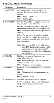
... night mode regardless of the screen from observation. Options: ON = Display a camera ID. See Adding a Camera ID Display. See Programming Day and Night Modes. SPECIAL Menu Functions Menu Item 1 CAMERA ID 2 DAY&NIGHT Description Sets a camera ID to set a privacy zone. Masks certain areas of the light level unless the LAMP connector is forced into night mode at all times. OFF = No privacy zones are set. Options: ON = A horizontal mirror image appears on the monitor...
... night mode regardless of the screen from observation. Options: ON = Display a camera ID. See Adding a Camera ID Display. See Programming Day and Night Modes. SPECIAL Menu Functions Menu Item 1 CAMERA ID 2 DAY&NIGHT Description Sets a camera ID to set a privacy zone. Masks certain areas of the light level unless the LAMP connector is forced into night mode at all times. OFF = No privacy zones are set. Options: ON = A horizontal mirror image appears on the monitor...
User Manual
Page 16
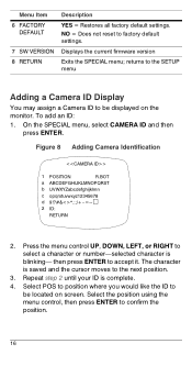
...: RETURN 2. then press ENTER to factory default settings. NO = Does not reset to accept it. Press the menu control UP, DOWN, LEFT, or RIGHT to confirm the position. 16 Select the position using the menu control, then press ENTER to select a character or number-selected character is blinking- Displays the current firmware version Exits the SPECIAL menu; On the SPECIAL menu, select CAMERA ID and then press ENTER. Repeat...
...: RETURN 2. then press ENTER to factory default settings. NO = Does not reset to accept it. Press the menu control UP, DOWN, LEFT, or RIGHT to confirm the position. 16 Select the position using the menu control, then press ENTER to select a character or number-selected character is blinking- Displays the current firmware version Exits the SPECIAL menu; On the SPECIAL menu, select CAMERA ID and then press ENTER. Repeat...
User Manual
Page 17
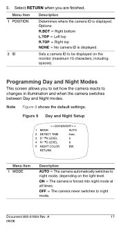
5. Figure 9 Day and Night Setup 1 MODE AUTO 2 DETECT TIME 3 D➝N LEVEL 4 N➝D LEVEL 5sec 5 8 5 NIGHT COLOR BW RETURN Menu Item 1 MODE Description AUTO = The camera automatically switches to be displayed on the light level. ON = The camera is displayed. Menu Item Description 1 POSITION Determines where the camera ID is forced into night mode at all times. Programming Day and Night Modes This screen allows you are finished. Options: R.BOT = Right bottom L.TOP = Left top R.TOP = Right top NONE...
5. Figure 9 Day and Night Setup 1 MODE AUTO 2 DETECT TIME 3 D➝N LEVEL 4 N➝D LEVEL 5sec 5 8 5 NIGHT COLOR BW RETURN Menu Item 1 MODE Description AUTO = The camera automatically switches to be displayed on the light level. ON = The camera is displayed. Menu Item Description 1 POSITION Determines where the camera ID is forced into night mode at all times. Programming Day and Night Modes This screen allows you are finished. Options: R.BOT = Right bottom L.TOP = Left top R.TOP = Right top NONE...
User Manual
Page 19
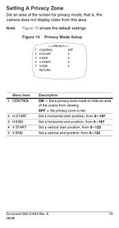
... Set a vertical start position, from 0~122 Set a vertical end position, from this area. that is set. Setting A Privacy Zone Set an area of the scene from viewing OFF = No privacy zone is , the camera does not display video from 0~122 Document 800-01954 Rev A 19 08/08 Note Figure 10 shows the default settings. Figure 10 Privacy Mode Setup 1 CONTROL OFF 2 H START 0 3 H END 0 4 V START 0 5 V END 0 RETURN Menu...
... Set a vertical start position, from 0~122 Set a vertical end position, from this area. that is set. Setting A Privacy Zone Set an area of the scene from viewing OFF = No privacy zone is , the camera does not display video from 0~122 Document 800-01954 Rev A 19 08/08 Note Figure 10 shows the default settings. Figure 10 Privacy Mode Setup 1 CONTROL OFF 2 H START 0 3 H END 0 4 V START 0 5 V END 0 RETURN Menu...

User Manual
Page 22
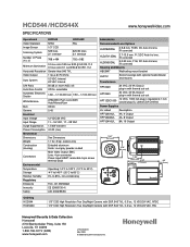
Specifications Operational Image Sensor: Video Standard: Scanning System: Number of Pixels (H x V): Minimum Illumination: Horizontal Resolution: Video Output: Sync System: S/N Ratio: Auto Gain Control: Automatic Electronic Shutter: White Balance: BLC: Gamma: Electrical Input Voltage: Input Range: Surge Suppression: Power Consumption: Mechanical Dimensions: Weight: Construction: (housing) HCD544 (NTSC) HCD544X (PAL) 1/3" CCD NTSC PAL 525 lines, 2:1 interlace 625/50 lines, 2:1 interlace 768 x 494 752 x 582 0.5 lux color/0.25 lux B/W @ 50...
Specifications Operational Image Sensor: Video Standard: Scanning System: Number of Pixels (H x V): Minimum Illumination: Horizontal Resolution: Video Output: Sync System: S/N Ratio: Auto Gain Control: Automatic Electronic Shutter: White Balance: BLC: Gamma: Electrical Input Voltage: Input Range: Surge Suppression: Power Consumption: Mechanical Dimensions: Weight: Construction: (housing) HCD544 (NTSC) HCD544X (PAL) 1/3" CCD NTSC PAL 525 lines, 2:1 interlace 625/50 lines, 2:1 interlace 768 x 494 752 x 582 0.5 lux color/0.25 lux B/W @ 50...
Brochure
Page 1
... then switches to black and white video to capture more detail using the increased sensitivity of resolution for changes in 24/7 surveillance applications. An on the back of the camera. The HCD544 produces 540 TV lines of the CCD to -use in light level, and automatic backlight compensation option for viewing backlit scenes. The HCD544 adapts to varying lighting conditions to black and white. Features • 1/3" CCD with...
... then switches to black and white video to capture more detail using the increased sensitivity of resolution for changes in 24/7 surveillance applications. An on the back of the camera. The HCD544 produces 540 TV lines of the CCD to -use in light level, and automatic backlight compensation option for viewing backlit scenes. The HCD544 adapts to varying lighting conditions to black and white. Features • 1/3" CCD with...
Brochure
Page 2
... sec White Balance ATW/AWC Push Lock/AWC Auto/Manual/User BLC Off/On Gamma 0.45 Electrical Input Voltage 12 VDC/24 VAC Input Range 11 - 16 VDC, 17 - 28 VAC Surge Suppression 1.5 kW transient Power Consumption 4.5 W (max) Mechanical Dimensions See Dimensions Weight 1.1 lb (.5 kg), camera only Construction (housing) Extruded aluminum Finish: cool gray powder coated Connectors Main Video Output: BNC Lens: 4-pin connector Power...
... sec White Balance ATW/AWC Push Lock/AWC Auto/Manual/User BLC Off/On Gamma 0.45 Electrical Input Voltage 12 VDC/24 VAC Input Range 11 - 16 VDC, 17 - 28 VAC Surge Suppression 1.5 kW transient Power Consumption 4.5 W (max) Mechanical Dimensions See Dimensions Weight 1.1 lb (.5 kg), camera only Construction (housing) Extruded aluminum Finish: cool gray powder coated Connectors Main Video Output: BNC Lens: 4-pin connector Power...


