
Owner's Manual
Page 1
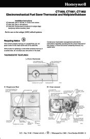
...Honeywell Inc. 1996 • Form Number 69-0394-3 M3375 HELD ON BY TWO CAPTIVE SCREWS.) M9615 D.F. • Rev. 11-96 • Printed in a sealed tube. CT1801 24V gas or oil heat/cool. If this control, or of an old control containing mercury in the trash at the end of thermostat. THERMOSTAT... FEATURES I-Front of its useful life. CT1802 24V central electric heat/cool or single stage heat pump without auxiliary heat. CT1800, CT1801, CT1802 Electromechanical Fuel Saver Thermostat and Wallplate/Subbase Installation Instructions CT1800 24V gas or oil ...
...Honeywell Inc. 1996 • Form Number 69-0394-3 M3375 HELD ON BY TWO CAPTIVE SCREWS.) M9615 D.F. • Rev. 11-96 • Printed in a sealed tube. CT1801 24V gas or oil heat/cool. If this control, or of an old control containing mercury in the trash at the end of thermostat. THERMOSTAT... FEATURES I-Front of its useful life. CT1802 24V central electric heat/cool or single stage heat pump without auxiliary heat. CT1800, CT1801, CT1802 Electromechanical Fuel Saver Thermostat and Wallplate/Subbase Installation Instructions CT1800 24V gas or oil ...
Owner's Manual
Page 2
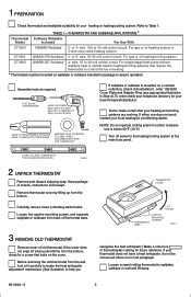
1 PREPARATION Check thermostat and wallplate suitability for your local Honeywell distributor. or 3- wire, 15-30 volt control circuit. wire, 15 to next paragraph. Test to make certain that locks on to 30 volt ... in package to help you 50 60 70 80 THERMOSTAT COVER LIFT COVER THERMOSTAT BASE CAPTIVE MOUNTING SCREWS M9617 recognize the heat anticipator.) Make a note here of screws, instructions and receipt. TABLE 1-THERMOSTAT AND SUBBASE APPLICATIONS.a Thermostat Subbase Wallplate Model Included For Use With CT1800 199986B Wallplate 2- For gas or oil heating system...
1 PREPARATION Check thermostat and wallplate suitability for your local Honeywell distributor. or 3- wire, 15-30 volt control circuit. wire, 15 to next paragraph. Test to make certain that locks on to 30 volt ... in package to help you 50 60 70 80 THERMOSTAT COVER LIFT COVER THERMOSTAT BASE CAPTIVE MOUNTING SCREWS M9617 recognize the heat anticipator.) Make a note here of screws, instructions and receipt. TABLE 1-THERMOSTAT AND SUBBASE APPLICATIONS.a Thermostat Subbase Wallplate Model Included For Use With CT1800 199986B Wallplate 2- For gas or oil heating system...
Owner's Manual
Page 3
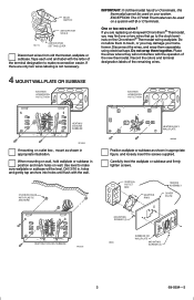
...-0394-3 Do not wrap them separately, using electrical tape. BULB SWITCH ANTICIPATOR SCALE M6115 ANTICIPATOR SETTING LEVER Disconnect wires from old thermostat, wallplate or subbase. If there are replacing a Honeywell Chronotherm® Thermostat, you are only two wires labeling is not necessary. 4 MOUNT WALLPLATE OR SUBBASE EXISTING HORIZONTAL OUTLET BOX IMPORTANT: If old...
...-0394-3 Do not wrap them separately, using electrical tape. BULB SWITCH ANTICIPATOR SCALE M6115 ANTICIPATOR SETTING LEVER Disconnect wires from old thermostat, wallplate or subbase. If there are replacing a Honeywell Chronotherm® Thermostat, you are only two wires labeling is not necessary. 4 MOUNT WALLPLATE OR SUBBASE EXISTING HORIZONTAL OUTLET BOX IMPORTANT: If old...
Owner's Manual
Page 4
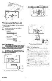
... AND OVERLOAD PROTECTION AS REQUIRED. The 4-wire drawing on the subbase. If the labels do not agree with nonflammable insulation to prevent drafts from affecting thermostat operation. 2-WIRE SYSTEM R W HEATING RELAY OR VALVE COIL 1 L2 L1 (HOT) 1 POWER SUPPLY. STRIP 7/16 in . [8 mm] SPIRIT ... STRAIGHT CONNECTION- STRIP 5/16 in . [11 mm] BARRIER M1556B FOR CT1800 heating-only For 2-wire system, connect either wire to R terminal and the other wire to Table 2 • Determine correct hookup from affecting thermostat operation. 69-0394-3 4 M2484B B W HEATING VALVE OR MOTOR 1 ...
... AND OVERLOAD PROTECTION AS REQUIRED. The 4-wire drawing on the subbase. If the labels do not agree with nonflammable insulation to prevent drafts from affecting thermostat operation. 2-WIRE SYSTEM R W HEATING RELAY OR VALVE COIL 1 L2 L1 (HOT) 1 POWER SUPPLY. STRIP 7/16 in . [8 mm] SPIRIT ... STRAIGHT CONNECTION- STRIP 5/16 in . [11 mm] BARRIER M1556B FOR CT1800 heating-only For 2-wire system, connect either wire to R terminal and the other wire to Table 2 • Determine correct hookup from affecting thermostat operation. 69-0394-3 4 M2484B B W HEATING VALVE OR MOTOR 1 ...

Owner's Manual
Page 5
... OVERLOAD PROTECTION AS REQUIRED. 2 IF COMPRESSOR IS CONNECTED TO OLD THERMOSTAT'S "Y" TERMINAL WITH A JUMPER TO "W", USE NEW THERMOSTAT'S "P" TERMINAL FOR COMPRESSOR. IF OLD THERMOSTAT HAS ONE WIRE TO "Y" AND ONE TO "W", USE "Y" AND "W" ON NEW THERMOSTAT; IMPORTANT- CENTRAL ELECTRIC SYSTEM W Y B P R O ... NOT DESIGNED TO CONTROL AUXILIARY HEAT. 3 SOME HEAT PUMPS USE "B" INSTEAD OF "O". DO NOT USE "P". IF OLD THERMOSTAT USES A W2 (AUXILIARY OR EMERGENCY HEAT) TERMINAL, THIS THERMOSTAT MAY NOT BE USED. M2414 1 L1 (HOT) L2 1 L1 (HOT) L2 1 POWER SUPPLY. M2412A SINGLE STAGE HEAT ...
... OVERLOAD PROTECTION AS REQUIRED. 2 IF COMPRESSOR IS CONNECTED TO OLD THERMOSTAT'S "Y" TERMINAL WITH A JUMPER TO "W", USE NEW THERMOSTAT'S "P" TERMINAL FOR COMPRESSOR. IF OLD THERMOSTAT HAS ONE WIRE TO "Y" AND ONE TO "W", USE "Y" AND "W" ON NEW THERMOSTAT; IMPORTANT- CENTRAL ELECTRIC SYSTEM W Y B P R O ... NOT DESIGNED TO CONTROL AUXILIARY HEAT. 3 SOME HEAT PUMPS USE "B" INSTEAD OF "O". DO NOT USE "P". IF OLD THERMOSTAT USES A W2 (AUXILIARY OR EMERGENCY HEAT) TERMINAL, THIS THERMOSTAT MAY NOT BE USED. M2414 1 L1 (HOT) L2 1 L1 (HOT) L2 1 POWER SUPPLY. M2412A SINGLE STAGE HEAT ...
Owner's Manual
Page 6
...to find the current draw for Step 3, this information can result in room temperature swings or burn out the anticipator and void the thermostat warranty. See next illustration. firmly tighten. If current rating is the number you recorded in Step 3 or found printed on -time ...DRAW SHOWS VOLTAGE 0.2 3A0MVPACRATING TO BURNER SHOWS ANTICIPATOR SETTING T T F F M6116B Move the heat anticipator to 2.0A for your system. Hang the thermostat base on the primary control as shown above, or as recorded in the bottom corners of the system. This is still unavailable, proceed as shown...
...to find the current draw for Step 3, this information can result in room temperature swings or burn out the anticipator and void the thermostat warranty. See next illustration. firmly tighten. If current rating is the number you recorded in Step 3 or found printed on -time ...DRAW SHOWS VOLTAGE 0.2 3A0MVPACRATING TO BURNER SHOWS ANTICIPATOR SETTING T T F F M6116B Move the heat anticipator to 2.0A for your system. Hang the thermostat base on the primary control as shown above, or as recorded in the bottom corners of the system. This is still unavailable, proceed as shown...
Owner's Manual
Page 7
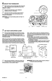
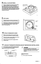
... AAA alkaline batteries. Do not reverse the minute hand. When time is supplied to the clock by moving the minute hand in the thermostat base. LOW TEMPERATURE (BLUE MARK) SET LEVER HIGH TEMPERATURE (RED MARK) SET LEVER CAUTION Do not check operation by shorting across terminals...System Turn on top of base. M9619 PROGRAM INDEX WHEEL TIME INDICATOR ARROW M2499 10 ATTACH THERMOSTAT COVER Make sure the packing inserts in the thermostat base have been removed, as explained in thermostat as shown in the illustration. 8 INSTALL CLOCK BATTERIES Power is correctly set, the Time ...
... AAA alkaline batteries. Do not reverse the minute hand. When time is supplied to the clock by moving the minute hand in the thermostat base. LOW TEMPERATURE (BLUE MARK) SET LEVER HIGH TEMPERATURE (RED MARK) SET LEVER CAUTION Do not check operation by shorting across terminals...System Turn on top of base. M9619 PROGRAM INDEX WHEEL TIME INDICATOR ARROW M2499 10 ATTACH THERMOSTAT COVER Make sure the packing inserts in the thermostat base have been removed, as explained in thermostat as shown in the illustration. 8 INSTALL CLOCK BATTERIES Power is correctly set, the Time ...
Owner's Manual
Page 8
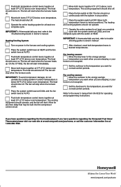
... room temperature. Heating/Cooling System Turn on power to the temperature you want when you have questions regarding the Honeywell Fuel Saver Thermostat please visit our web site at www.honeywell.com/yourhome, or call the customer information line at ON. Place the fan switch at 1-800-468-1502.... 69-0394-369-0846 8 4 Helping You Control Your World www.honeywell.com/yourhome Place the system switch at AUTO....
... room temperature. Heating/Cooling System Turn on power to the temperature you want when you have questions regarding the Honeywell Fuel Saver Thermostat please visit our web site at www.honeywell.com/yourhome, or call the customer information line at ON. Place the fan switch at 1-800-468-1502.... 69-0394-369-0846 8 4 Helping You Control Your World www.honeywell.com/yourhome Place the system switch at AUTO....


