Honeywell CT1503 Support and Manuals
Get Help and Manuals for this Honeywell item

View All Support Options Below
Free Honeywell CT1503 manuals!
Problems with Honeywell CT1503?
Ask a Question
Free Honeywell CT1503 manuals!
Problems with Honeywell CT1503?
Ask a Question
Popular Honeywell CT1503 Manual Pages
Owner's Manual - Page 1
...--24 V central electric heat/cool or single stage heat pump without
auxiliary heat.
NOT FOR USE ON LINE VOLTAGE (120 V) SYSTEMS.
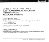
INSTALLATION MANUAL
Any questionsconcerningthe applicationofthis thermostat should be directedto HoneywellConsumer Services at 1-800-468-1502, Monday-Friday 7 3 0 a.m.-500 pm., Central time. CTI503-750 millivolt heat. Rev. 7-91 aHoneywell Inc. 1991 Form Number...
Owner's Manual - Page 2
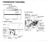
HlGH TEMPERATURE
1 CONTROL LEVER (RED)
LOW TEMPERATURE CONTROL LEVER (BLUE)- PROGRAM PINS A
"---
Ill-Cover removed.
24 HOUR PROGRAM DIAL
'THERMOSTAT COVER
THERMOMETER 1
11.711
Il-Hinged cover lifted.
.. .~
. ,.....
. CAPTIVE MOUNTING
ANTICIPATOR
HIND THERMOSTAT.
THERMOSTAT FEATURES
I-Front of thermostat. H E L D O N BY TWO CAPTIVE SCREWS.)
Owner's Manual - Page 3
... mill volt single-stage heating system.
"1k
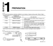
PREPARATION
((1
THERMOSTAT MODEL
SUBBASE OR WALLPLATE INCLUDED
FOR USE WITH
CT1500
199986C Wallplate
2-wire, 15 to 30 volt control circuit. IF NEEDED TO LABELWIRESASTHEYARE OISCONNECTED FROM OLD THERMOSTAT
CT1502 CT1503
Q682B1227 Subbase 199986D Wailp ate
4-wire, 15 to 30 volt control circuit For gas or oil heating system. or...
Owner's Manual - Page 4
....
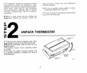
If either one
does not work, contact your heating and cooling systems are working.
THERMOIIAT
.. Call Honeywell Consumer Services (1-800-468-1502) for ordering information, Monday-Friday, 7:30 a.m. Save package of screws, instructions and receipt
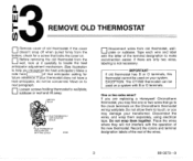
Remove thermostat cover by lifting up from the bottom.
0Carefully remove insert protecting switch bulbs.
0Loosen two captive mounting...
Owner's Manual - Page 5
..., or you may find one or two wires that locks the cover on the Chronotherm thermostat wiring wallplate. IMPORTANT
thermostat cannot be concerned. Place the wires where they will not interfere with B or 0 terminals. If there are replacing a Honeywell Chronotherm thermostat,you may damage your transformer.
Disconnect the wires, and wrap them together. Move on...
Owner's Manual - Page 10
... control circuit.
P
Heat pump compressor control
Push excess wire back into wall. I - M%1*
8
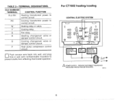
For CT1502 heatinglcooling
CENTRAL ELECTRIC SYSTEM
I 1 II U
CONTACTOR
RELAY OR VALVE COIL
A POWER SUPPLY. OLDSUBBASE TERMINAL
CONTROL FUNCTION
R or RH
Heating transformer power to control circuit
RC
Cooling transformer power to prevent drafts from affecting thermostat operation...
Owner's Manual - Page 11

... insulation to W terminal. M24IB
9
/
1 0
CQZOOA OR 0313A
THERMOPILE
69-0273-9 U S t ' Y AND " W ' O N NEW
THERMOSTAT, DO NOT U S E " P . IF OLD
THERMOSTAT USES A W2 (AUXILIARY OR EMERGENCY HEAT)
TERMINAL, THIS THERMOSTAT MAY NOT BE USED THIS
THERMOSTAT IS NOT DESIGNED TO CONTROL AUXILIARY HEAT
A SOMEHEATPUMPSUSE"B"INSTEAD0F"O'
M211511
0Connect the wires to prevent drafts from...
Owner's Manual - Page 13
...:
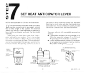
Coqnect the probes of the system. An incorrect setting can result in Step 3 If you have the current draw (anticipator setting) for example) between R (or RH) and W terminals on the primary control at least one minute before taklng reading. NOTE: Not applicable on CT1503 millivolt model.
0The thermostat's adjustable heat anticipator must be found printed on...
Owner's Manual - Page 14
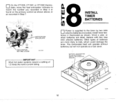
... batteries are dead, replace with two new AAA alkaline batteries. Once a year, or when batteries are more likely to match the number you recorded in Step 4 or found on the primary control as shown above, or as recorded in Step 7
"8INSTALL
F
TIMER BATTERIES
0
\ANTICIPATOR SETTING LEVER
11,7164\
teries in thermostat as a fuel saver...
Owner's Manual - Page 15
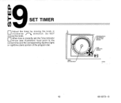
When time is correctly set, the Time Indicator
Arrow (see illustration) must point to the
correct time and the corresponding daytime (lighr)
or nighitime (dark) portion of the program dial.
13
69-0273-9
SET TIMER
0Adjust the timer by moving the knob in
clockwise
direction. Do NOT
reverse the knob.
Owner's Manual - Page 16
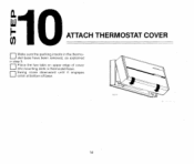
ATTACH THERMOSTAT COVER
0Make sure the packing inserts in thermostat base
0Swing cover downward until it engages catch at bottom of cover into mounting slots in the thermostat base have been removed. as explained in step 3
0Place the two tabs on upper edge of base
..
14 "10 0I-
Owner's Manual - Page 17
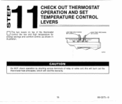
cin l1CHECK OUT THERMOSTAT
OPERATION AND SET
b
TEMPERATURE CONTROL LEVERS
The two levers on top of relay or valve coil; LOW TEMP.lBL"E MARK1 SET LEVER
1
Do NOT check operation by shorting across terminals of the thermostat control the low and high temperature for energy savings and comfort control, as shown in illustration. I
15
69-0273-9
~ this will...
Owner's Manual - Page 18
.... IMPORTANT If thermostat fails any position.
0 Place the system switch at ON. IMPORTANT If thermostat fails any time delay that may be built into the compressor control circuit.
0 ... one complete cycle with the system switch in any test, refer to troubleshooting guide in owner's manual.
The heat should comeon.Thefan will start immediately.
0 Moveboth leverstogether5"F[3"C]belowroom...
Owner's Manual - Page 19
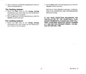
... the energy savings temperature you wantfor normal comfort periods. IF YOU HAVE OUESTIONS REGARDING THE INSTALLATION OF THE HONEYWELL FUEL SAVER THERMOSTAT, PLEASECALL OUR TOLLFREE CONSUMER SERVICES GROUP NUMBER
AT 1-800-468-1502, MONDAY-FRIDAY, 7:30 AM -
5:OO PM ... comfort periods. For heating season:
[?
REFER TO THE OWNERS MANUAL FORM 690333FOR OPERATING AND PROGRAMMING INSTRUCTIONS.
Owner's Manual - Page 20
Residential and Building Controls Division Honeywell Inc. 1985 Douglas Drive No. Golden Valley, MN 55422
Residential and Building Controls Division Honeywell Limited-Honeywell 740 Ellesmere Road Scarborough, Ontario M1P 2VY
Lunltke
Honeywell
Helping You Conlrol Your World
Honeywell CT1503 Reviews
We have not received any reviews for Honeywell yet.