
Owner's Manual
Page 1
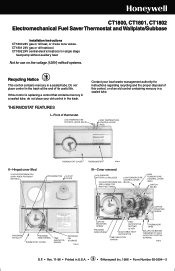
...Installation Instructions CT1800 24V gas or oil heat, or 3 wire zone valves. AAA ALKALINE BATTERY (2) INCLUDED LOW TEMPERATURE CONTROL LEVER 24 HOUR PROGRAM DIAL (BLUE) (GRAY AREA FOR NIGHT SETTINGS) HIGH TEMPERATURE CONTROL LEVER (RED) SWITCH BULBS PROGRAM PIN SLOT PROGRAM INDEX WHEEL THERMOSTAT COVER TIME INDICATOR ARROW PROGRAM PIN STORAGE M9614 CAPTIVE MOUNTING SCREW CAPTIVE MOUNTING SCREW PROGRAM INDEX WHEEL HEAT ANTICIPATOR SETTING LEVER ADJUSTABLE HEAT ANTICIPATOR TIME INDICATOR ARROW THERMOSTAT BASE WALLPLATE (BEHIND THERMOSTAT. THERMOSTAT FEATURES I-Front of an old...
...Installation Instructions CT1800 24V gas or oil heat, or 3 wire zone valves. AAA ALKALINE BATTERY (2) INCLUDED LOW TEMPERATURE CONTROL LEVER 24 HOUR PROGRAM DIAL (BLUE) (GRAY AREA FOR NIGHT SETTINGS) HIGH TEMPERATURE CONTROL LEVER (RED) SWITCH BULBS PROGRAM PIN SLOT PROGRAM INDEX WHEEL THERMOSTAT COVER TIME INDICATOR ARROW PROGRAM PIN STORAGE M9614 CAPTIVE MOUNTING SCREW CAPTIVE MOUNTING SCREW PROGRAM INDEX WHEEL HEAT ANTICIPATOR SETTING LEVER ADJUSTABLE HEAT ANTICIPATOR TIME INDICATOR ARROW THERMOSTAT BASE WALLPLATE (BEHIND THERMOSTAT. THERMOSTAT FEATURES I-Front of an old...
Owner's Manual
Page 2
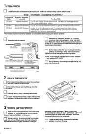
.... For single-stage heat pump without auxiliary heat or central electric heating/cooling systems that anticipator setting for your heating or heating/cooling system. TABLE 1-THERMOSTAT AND SUBBASE APPLICATIONS.a Thermostat Subbase Wallplate Model Included For Use With CT1800 199986B Wallplate 2- wire, 150 to Table 1. CT1801 Q682A1079 Subbase 4- or 5- NOTE: Do not operate cooling sytem if outdoor temperature is mounted on the cover. Assemble tools as required. If your thermostat does not have a heat anticipator, do not...
.... For single-stage heat pump without auxiliary heat or central electric heating/cooling systems that anticipator setting for your heating or heating/cooling system. TABLE 1-THERMOSTAT AND SUBBASE APPLICATIONS.a Thermostat Subbase Wallplate Model Included For Use With CT1800 199986B Wallplate 2- wire, 150 to Table 1. CT1801 Q682A1079 Subbase 4- or 5- NOTE: Do not operate cooling sytem if outdoor temperature is mounted on the cover. Assemble tools as required. If your thermostat does not have a heat anticipator, do not...
Owner's Manual
Page 3
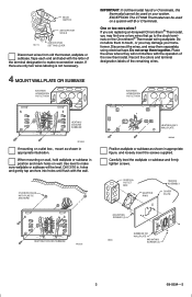
..., using electrical tape. EXISTING HORIZONTAL OUTLET BOX R G FAN ON AUTO O B W Y HEAT COOL OFF HEATING/ COOLING SUBBASE M1553A If mounting on wall. When mounting on a system with the operation of the remaining wires. If there are replacing a Honeywell Chronotherm® Thermostat, you are only two wires labeling is not necessary. 4 MOUNT WALLPLATE OR SUBBASE EXISTING HORIZONTAL OUTLET BOX IMPORTANT: If old thermostat has B or O terminals, this thermostat cannot be used on wall, hold...
..., using electrical tape. EXISTING HORIZONTAL OUTLET BOX R G FAN ON AUTO O B W Y HEAT COOL OFF HEATING/ COOLING SUBBASE M1553A If mounting on wall. When mounting on a system with the operation of the remaining wires. If there are replacing a Honeywell Chronotherm® Thermostat, you are only two wires labeling is not necessary. 4 MOUNT WALLPLATE OR SUBBASE EXISTING HORIZONTAL OUTLET BOX IMPORTANT: If old thermostat has B or O terminals, this thermostat cannot be used on wall, hold...
Owner's Manual
Page 4
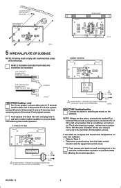
... matching terminals on . STRIP 7/16 in . [8 mm] SPIRIT LEVEL R G FAN ON AUTO O B W Y HEAT COOL OFF M2419 3-WIRE SYSTEM R W FOR WRAPAROUND CONNECTION- Firmly tighten screws. M2485B FOR CT1801 heating/cooling Connect the wires to Table 2 • Determine correct hookup from the listed control function and the equipment control circuit. PROVIDE DISCONNECT MEANS AND OVERLOAD PROTECTION AS REQUIRED. If RC is left unconnected, the air conditioner will not turn on...
... matching terminals on . STRIP 7/16 in . [8 mm] SPIRIT LEVEL R G FAN ON AUTO O B W Y HEAT COOL OFF M2419 3-WIRE SYSTEM R W FOR WRAPAROUND CONNECTION- Firmly tighten screws. M2485B FOR CT1801 heating/cooling Connect the wires to Table 2 • Determine correct hookup from the listed control function and the equipment control circuit. PROVIDE DISCONNECT MEANS AND OVERLOAD PROTECTION AS REQUIRED. If RC is left unconnected, the air conditioner will not turn on...

Owner's Manual
Page 5
... AS REQUIRED. 2 IF COMPRESSOR IS CONNECTED TO OLD THERMOSTAT'S "Y" TERMINAL WITH A JUMPER TO "W", USE NEW THERMOSTAT'S "P" TERMINAL FOR COMPRESSOR. IF OLD THERMOSTAT HAS ONE WIRE TO "Y" AND ONE TO "W", USE "Y" AND "W" ON NEW THERMOSTAT; M2415B 5 69-0394-3 PROVIDE DISCONNECT MEANS AND OVERLOAD PROTECTION AS REQUIRED. 2 INSTALL JUMPER BETWEEN RC AND RH. M2414 1 L1 (HOT) L2 1 L1 (HOT) L2 1 POWER SUPPLY. CENTRAL ELECTRIC SYSTEM W Y B P R O G FAN ON AUTO HEAT COOL OFF COOLING CONTACTOR COIL FAN RELAY HEATING RELAY OR VALVE COIL...
... AS REQUIRED. 2 IF COMPRESSOR IS CONNECTED TO OLD THERMOSTAT'S "Y" TERMINAL WITH A JUMPER TO "W", USE NEW THERMOSTAT'S "P" TERMINAL FOR COMPRESSOR. IF OLD THERMOSTAT HAS ONE WIRE TO "Y" AND ONE TO "W", USE "Y" AND "W" ON NEW THERMOSTAT; M2415B 5 69-0394-3 PROVIDE DISCONNECT MEANS AND OVERLOAD PROTECTION AS REQUIRED. 2 INSTALL JUMPER BETWEEN RC AND RH. M2414 1 L1 (HOT) L2 1 L1 (HOT) L2 1 POWER SUPPLY. CENTRAL ELECTRIC SYSTEM W Y B P R O G FAN ON AUTO HEAT COOL OFF COOLING CONTACTOR COIL FAN RELAY HEATING RELAY OR VALVE COIL...
Owner's Manual
Page 6
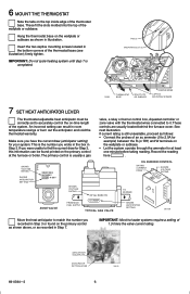
... W terminals on the primary control as shown above, or as follows: • Connect the probes of the wallplate or subbase. This is usually a gas valve, a relay or burner control box, Aquastat controller or zone valve with the thermostat wires connected to match the number you wrote in the box in room temperature swings or burn out the anticipator and void the thermostat warranty. The...
... W terminals on the primary control as shown above, or as follows: • Connect the probes of the wallplate or subbase. This is usually a gas valve, a relay or burner control box, Aquastat controller or zone valve with the thermostat wires connected to match the number you wrote in the box in room temperature swings or burn out the anticipator and void the thermostat warranty. The...
Owner's Manual
Page 7
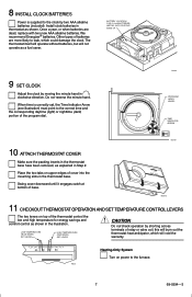
... System Turn on top of the thermostat control the low and high temperature for energy savings and comfort control as shown. BATTERY LOCATION FOR (2) AAA BATTERIES; Once a year, or when batteries are more likely to leak, which will not operate as explained in Step 2. M9618 11 CHECKOUTTHERMOSTAT OPERATION AND SETTEMPERATURE CONTROL LEVERS The two levers on power to the furnace. 7 69-0394-3 8 INSTALL CLOCK BATTERIES Power is correctly set, the Time Indicator...
... System Turn on top of the thermostat control the low and high temperature for energy savings and comfort control as shown. BATTERY LOCATION FOR (2) AAA BATTERIES; Once a year, or when batteries are more likely to leak, which will not operate as explained in Step 2. M9618 11 CHECKOUTTHERMOSTAT OPERATION AND SETTEMPERATURE CONTROL LEVERS The two levers on power to the furnace. 7 69-0394-3 8 INSTALL CLOCK BATTERIES Power is correctly set, the Time Indicator...
Owner's Manual
Page 8
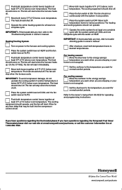
... temperature. Move both temperature control levers together at 1-800-468-1502. 69-0394-369-0846 8 4 Helping You Control Your World www.honeywell.com/yourhome Move both temperature levers to the Troubleshooting Guide in owner's manual. IMPORTANT: If thermostat fails any test, refer to desired temperatures. Place the system switch lever at HEAT and the fan switch lever at OFF. Set the red lever to the temperature you are sleeping or your home...
... temperature. Move both temperature control levers together at 1-800-468-1502. 69-0394-369-0846 8 4 Helping You Control Your World www.honeywell.com/yourhome Move both temperature levers to the Troubleshooting Guide in owner's manual. IMPORTANT: If thermostat fails any test, refer to desired temperatures. Place the system switch lever at HEAT and the fan switch lever at OFF. Set the red lever to the temperature you are sleeping or your home...


