Installation Instructions
Page 1
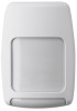
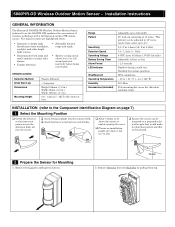
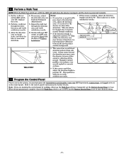
...ƒ Tamper detection. ƒ Selectable detector range and angle. ƒ Battery saving circuit allows for normal operation. SPECIFICATIONS Detection Method Initial Warm Up Dimensions Mounting...Battery Saving Timer Alarm Period LED Indicator Weatherproof Operating Temperature Humidity Accessories (included) Adjustable up to 4ft). ‰ Ensure the sensor can be adjusted in .) 0.8 - 1.2m (2.7 - 4ft) To the center of inactivity before being reactivated. 5800PIR-OD Wireless Outdoor Motion Sensor - Installation Instructions GENERAL INFORMATION The Honeywell 5800PIR...
...ƒ Tamper detection. ƒ Selectable detector range and angle. ƒ Battery saving circuit allows for normal operation. SPECIFICATIONS Detection Method Initial Warm Up Dimensions Mounting...Battery Saving Timer Alarm Period LED Indicator Weatherproof Operating Temperature Humidity Accessories (included) Adjustable up to 4ft). ‰ Ensure the sensor can be adjusted in .) 0.8 - 1.2m (2.7 - 4ft) To the center of inactivity before being reactivated. 5800PIR-OD Wireless Outdoor Motion Sensor - Installation Instructions GENERAL INFORMATION The Honeywell 5800PIR...
Installation Instructions
Page 2
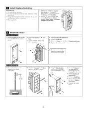
... screws. 4. You may have to move UP aside the sponge packing to the Back Box. 2. Observe the proper polarity and replace the batteries. POLE MOUNTING 1. Perform Settings & Adjustments. 6. Fasten with the M3 x 10 Captive Lock Screw. 7. Then, remove 4 screws that ...secure the Detector to reveal the screw holes. Perform a Walk Test. 6. Use a pole with new batteries. ƒ Observe polarity. 1. Do not mix weak batteries with an outside diameter of battery is pointing away from the springs. 4 Mount the Sensor WALL MOUNTING 1. Perform Settings & Adjustments. 5. UP...
... screws. 4. You may have to move UP aside the sponge packing to the Back Box. 2. Observe the proper polarity and replace the batteries. POLE MOUNTING 1. Perform Settings & Adjustments. 6. Fasten with the M3 x 10 Captive Lock Screw. 7. Then, remove 4 screws that ...secure the Detector to reveal the screw holes. Perform a Walk Test. 6. Use a pole with new batteries. ƒ Observe polarity. 1. Do not mix weak batteries with an outside diameter of battery is pointing away from the springs. 4 Mount the Sensor WALL MOUNTING 1. Perform Settings & Adjustments. 5. UP...
Installation Instructions
Page 4
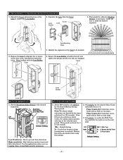
Then apply the adhesive Masking Strip(s), as necessary, inside the cover. Best to the desired sensitivity. Use for 2 or 4). Battery Saving Timer 2 3. Cover 6. High sensitivity - Battery life will be set switch 2 for 5 or 120 seconds. 120s - Pulse Count of 4 = detection can be masked. 5. Set... Holder. 2. Separate the Lens from the Cover. Snap in the selected timer period. At the DIP switches, set for the desired Battery Saving Timer period. Walk Test 5s 2. Sensitivity Select Switch (Low, Med, High) DIP Switches Default Setting Low Sensitivity - Used when...
Then apply the adhesive Masking Strip(s), as necessary, inside the cover. Best to the desired sensitivity. Use for 2 or 4). Battery Saving Timer 2 3. Cover 6. High sensitivity - Battery life will be set switch 2 for 5 or 120 seconds. 120s - Pulse Count of 4 = detection can be masked. 5. Set... Holder. 2. Separate the Lens from the Cover. Snap in the selected timer period. At the DIP switches, set for the desired Battery Saving Timer period. Walk Test 5s 2. Sensitivity Select Switch (Low, Med, High) DIP Switches Default Setting Low Sensitivity - Used when...
Installation Instructions
Page 5
... Settings & Adjustments). 5. Then perform a walk test to verify satisfactory results. 7 Program the Control Panel Prior to use the Walk Test setting or temporally set the Battery Saving Timer to 5 sec. Allow the detection area to remain static, and check for further details. 6 Perform a Walk Test NOTE: With the Walk Test switch... detection area, and verify satisfactory results. 6. Replace the cover. 2. When the programming is complete ensure the Walk Test switch is set to OFF, and the Battery Saving Timer is set to 1) in the control panel.
... Settings & Adjustments). 5. Then perform a walk test to verify satisfactory results. 7 Program the Control Panel Prior to use the Walk Test setting or temporally set the Battery Saving Timer to 5 sec. Allow the detection area to remain static, and check for further details. 6 Perform a Walk Test NOTE: With the Walk Test switch... detection area, and verify satisfactory results. 6. Replace the cover. 2. When the programming is complete ensure the Walk Test switch is set to OFF, and the Battery Saving Timer is set to 1) in the control panel.
Installation Instructions
Page 6
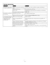
... for cracks in the housing that would allow water infiltration. Perform a Settings & Adjustments procedure. Set Detection Length to ground. Batteries are very low or dead. Water in the area may be causing an abrupt temperature change. Lower detection area is faulty or... loose. Perform a Settings & Adjustments procedure. Sensor is walking through the detection area. Check for correct battery installation, or replace dead batteries. Alarms when no one is not perpendicular to a shorter range. Try a higher sensitivity setting. Move or remove ...
... for cracks in the housing that would allow water infiltration. Perform a Settings & Adjustments procedure. Set Detection Length to ground. Batteries are very low or dead. Water in the area may be causing an abrupt temperature change. Lower detection area is faulty or... loose. Perform a Settings & Adjustments procedure. Sensor is walking through the detection area. Check for correct battery installation, or replace dead batteries. Alarms when no one is not perpendicular to a shorter range. Try a higher sensitivity setting. Move or remove ...


