
Owner's Manual
Page 2
... end of energy savings with your new Honeywell thermostat. Your new thermostat will automatically lower and raise the temperature in a sealed tube, do not place your local waste management authority for instructions regarding recycling and the proper disposal of this control, or of accurate control and reliable operation for years to come. Read this control is your fuel costs, while awakening (or returning home) to...
... end of energy savings with your new Honeywell thermostat. Your new thermostat will automatically lower and raise the temperature in a sealed tube, do not place your local waste management authority for instructions regarding recycling and the proper disposal of this control, or of accurate control and reliable operation for years to come. Read this control is your fuel costs, while awakening (or returning home) to...
Owner's Manual
Page 3
Table of Contents Page Features of Your Thermostat ...4 Setting the Temperature ...7 Inserting Timer Batteries ...8 Setting the Timer ...9 Programming ...10 Setting Subbase Switches ...13 Troubleshooting ...14 Servicing the Thermostat ...22 Cycle Rate Adjustment ...22 Thermometer Adjustment ...23 Warranty ...27 3 69-0643-1
Table of Contents Page Features of Your Thermostat ...4 Setting the Temperature ...7 Inserting Timer Batteries ...8 Setting the Timer ...9 Programming ...10 Setting Subbase Switches ...13 Troubleshooting ...14 Servicing the Thermostat ...22 Cycle Rate Adjustment ...22 Thermometer Adjustment ...23 Warranty ...27 3 69-0643-1
Owner's Manual
Page 4
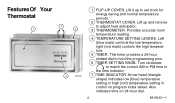
.... 4 TEMPERATURE SETTING LEVERS. Arrow head (triangle shape) indicates low (blue) temperature setting or high (red) temperature setting in control on 24-hour dial. 4 69-0643-1 Left (blue mark) controls the low temperature, right (red mark) controls the high temperature. 5 TIMER. Lift it up and remove to set clock for energy saving and normal temperature periods. 2 THERMOSTAT COVER. This timer provides a 24-hour slotted dial to the time indicator. 7 TIME INDICATOR. Also indicates time on program index wheel. FeaturesOf Your Thermostat 4 1 2 3 M7349 1 FLIP-UP COVER. Turn...
.... 4 TEMPERATURE SETTING LEVERS. Arrow head (triangle shape) indicates low (blue) temperature setting or high (red) temperature setting in control on 24-hour dial. 4 69-0643-1 Left (blue mark) controls the low temperature, right (red mark) controls the high temperature. 5 TIMER. Lift it up and remove to set clock for energy saving and normal temperature periods. 2 THERMOSTAT COVER. This timer provides a 24-hour slotted dial to the time indicator. 7 TIME INDICATOR. Also indicates time on program index wheel. FeaturesOf Your Thermostat 4 1 2 3 M7349 1 FLIP-UP COVER. Turn...

Owner's Manual
Page 5
... specific time of day as set by switching the heating or cooling system on or off. 5 5 6 10 14 9 11 8 7 12 13 M7350 69-0643-1 Provide automatic temperature control by program pins. 9 PROGRAM PINS. Calibrated to indicator nighttime. 12 HEAT ANTICIPATOR SCALEPLATE. Must be inserted into 24hour timer dial slots to match the heating system primary control current. 14 MERCURY BULB AND BIMETAL ELEMENT (2). 8 PROGRAM INDEX WHEEL. Must be adjusted to control program...
... specific time of day as set by switching the heating or cooling system on or off. 5 5 6 10 14 9 11 8 7 12 13 M7350 69-0643-1 Provide automatic temperature control by program pins. 9 PROGRAM PINS. Calibrated to indicator nighttime. 12 HEAT ANTICIPATOR SCALEPLATE. Must be inserted into 24hour timer dial slots to match the heating system primary control current. 14 MERCURY BULB AND BIMETAL ELEMENT (2). 8 PROGRAM INDEX WHEEL. Must be adjusted to control program...
Owner's Manual
Page 6
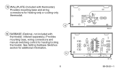
See Setting Subbase Switches section for heating-only or cooling-only thermostat. 15 16 SUBBASE (Optional, not included with thermostat; 15 WALLPLATE (Included with thermostat.) Provides mounting base and wiring connections for additional information. 16 6 M2421 R G FAN ON AUTO O B W Y HEAT COOL OFF M 719 69-0643-1 ordered separately.) Provides mounting base, wiring connections and manual switching control for heating/cooling thermostat.
See Setting Subbase Switches section for heating-only or cooling-only thermostat. 15 16 SUBBASE (Optional, not included with thermostat; 15 WALLPLATE (Included with thermostat.) Provides mounting base and wiring connections for additional information. 16 6 M2421 R G FAN ON AUTO O B W Y HEAT COOL OFF M 719 69-0643-1 ordered separately.) Provides mounting base, wiring connections and manual switching control for heating/cooling thermostat.

Owner's Manual
Page 7
NOTE: You may override the time program by setting both the red and blue levers to the same temperature setpoint. For Cooling: ■ Set the left lever (blue mark) to the energy saving temperature you want when you want when you are sleeping or your home is unoccupied. ■ Set the right lever (red mark) to the temperature you are sleeping or your home is unoccupied. 7 LOW TEMPERATURE SETTING LEVER 50...
NOTE: You may override the time program by setting both the red and blue levers to the same temperature setpoint. For Cooling: ■ Set the left lever (blue mark) to the energy saving temperature you want when you want when you are sleeping or your home is unoccupied. ■ Set the right lever (red mark) to the temperature you are sleeping or your home is unoccupied. 7 LOW TEMPERATURE SETTING LEVER 50...
Owner's Manual
Page 8
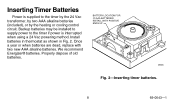
... alkaline batteries (included), or by the heating or cooling control circuit. BATTERY LOCATION FOR (2) AAA BATTERIES; Once a year or when batteries are dead, replace with two new AAA alkaline batteries. Properly dispose of old batteries. INSTALL WITH POSITIVE ENDS UP M8585 Fig. 2-Inserting timer batteries. 8 69-0643-1 We recommend Energizer® batteries. Inserting Timer Batteries Power is supplied to the timer if power is interrupted when using a 24 Vac powering method. Install batteries in thermostat as...
... alkaline batteries (included), or by the heating or cooling control circuit. BATTERY LOCATION FOR (2) AAA BATTERIES; Once a year or when batteries are dead, replace with two new AAA alkaline batteries. Properly dispose of old batteries. INSTALL WITH POSITIVE ENDS UP M8585 Fig. 2-Inserting timer batteries. 8 69-0643-1 We recommend Energizer® batteries. Inserting Timer Batteries Power is supplied to the timer if power is interrupted when using a 24 Vac powering method. Install batteries in thermostat as...
Owner's Manual
Page 9
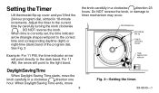
... point directly to the light band. PROGRAM DIAL PROGRAM PIN (6) TIMER SETTING KNOB TIME INDICATOR ARROW Daylight Saving Time M 821 When Daylight Saving Time starts, move 9 TIME INDICATOR ARROW Fig. 3-Setting the timer. 69-0643-1 When Daylight Saving Time ends, move the knob carefully in 10-minute increments. For 11 AM, the arrow will point to timer mechanism may occur. Setting the Timer ■ Lift thermostat flip-up cover and...
... point directly to the light band. PROGRAM DIAL PROGRAM PIN (6) TIMER SETTING KNOB TIME INDICATOR ARROW Daylight Saving Time M 821 When Daylight Saving Time starts, move 9 TIME INDICATOR ARROW Fig. 3-Setting the timer. 69-0643-1 When Daylight Saving Time ends, move the knob carefully in 10-minute increments. For 11 AM, the arrow will point to timer mechanism may occur. Setting the Timer ■ Lift thermostat flip-up cover and...
Owner's Manual
Page 10
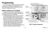
.... A heating program has been preprogrammed. The dial is inserted at 10-minute intervals. ■ Three red and three blue program pins are for high PROGRAM PINS THERMOSTAT COVER PROGRAM PIN SLOT PROGRAM INDEX WHEEL TIME INDICATOR ARROW PROGRAM PIN STORAGE M7348 Fig. 4-Program components. 10 69-0643-1 the blue pins start the high-temperature period; FLIP-UP COVER 24-HOUR PROGRAM DIAL (GRAY AREA FOR NIGHT SETTINGS...
.... A heating program has been preprogrammed. The dial is inserted at 10-minute intervals. ■ Three red and three blue program pins are for high PROGRAM PINS THERMOSTAT COVER PROGRAM PIN SLOT PROGRAM INDEX WHEEL TIME INDICATOR ARROW PROGRAM PIN STORAGE M7348 Fig. 4-Program components. 10 69-0643-1 the blue pins start the high-temperature period; FLIP-UP COVER 24-HOUR PROGRAM DIAL (GRAY AREA FOR NIGHT SETTINGS...

Owner's Manual
Page 11
... the comfort level. See Setting Subbase Switches section. • On heating/cooling systems, you want the energy saving period to start gives the furnace time to heat the house before this time. The furnace will also probably want to six temperature changes with the program index wheel. • On heating/cooling systems, set the heating program: ■ Decide when you must reset the pins when the seasons change a pin if it...
... the comfort level. See Setting Subbase Switches section. • On heating/cooling systems, you want the energy saving period to start gives the furnace time to heat the house before this time. The furnace will also probably want to six temperature changes with the program index wheel. • On heating/cooling systems, set the heating program: ■ Decide when you must reset the pins when the seasons change a pin if it...

Owner's Manual
Page 12
... when you want the energy saving period to cool the house before this time. The half-hour head start gives the air conditioner time to start and insert a red pin at the notch that is in effect. WINTER SUMMER PROGRAM PROGRAM TEMPERATURE PIN IN TEMPERATURE PIN IN °F °C CONTROL °F °C CONTROL NIGHT BEGINS 58 14 BLUE 80 27 RED ENERGY 10:00 PM SAVING...
... when you want the energy saving period to cool the house before this time. The half-hour head start gives the air conditioner time to start and insert a red pin at the notch that is in effect. WINTER SUMMER PROGRAM PROGRAM TEMPERATURE PIN IN TEMPERATURE PIN IN °F °C CONTROL °F °C CONTROL NIGHT BEGINS 58 14 BLUE 80 27 RED ENERGY 10:00 PM SAVING...
Owner's Manual
Page 13
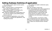
... switch positions, use thumb or index finger to slide the lever to the desired position. OFF-Both the heating and cooling systems are off . ON-Fan operates continuously. For proper circuit operation, switch lever must stop in heating and cooling. COOL-Cooling system is also off. In electric heat, heat pump and fan coil systems, the fan is off . AUTO-Fan operates with cooling equipment as controlled by the thermostat in detent over desired function indicator...
... switch positions, use thumb or index finger to slide the lever to the desired position. OFF-Both the heating and cooling systems are off . ON-Fan operates continuously. For proper circuit operation, switch lever must stop in heating and cooling. COOL-Cooling system is also off. In electric heat, heat pump and fan coil systems, the fan is off . AUTO-Fan operates with cooling equipment as controlled by the thermostat in detent over desired function indicator...
Owner's Manual
Page 14
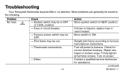
... switch to furnace. Turn off power to HEAT position. Firmly tighten all terminal screws. System switch may be out. - Check for assistance. (continued) 69-0643-1 Thermostat connections. - Move switch to the following. Most problems can generally be OFF. - Pilot flame may be traced to ON . Relight pilot flame according to furnace manufacturer instructions. If blown or tripped, replace fuse or reset breaker. Problem No heat. 2 Check - Troubleshooting Your Honeywell thermostat...
... switch to furnace. Turn off power to HEAT position. Firmly tighten all terminal screws. System switch may be out. - Check for assistance. (continued) 69-0643-1 Thermostat connections. - Move switch to the following. Most problems can generally be OFF. - Pilot flame may be traced to ON . Relight pilot flame according to furnace manufacturer instructions. If blown or tripped, replace fuse or reset breaker. Problem No heat. 2 Check - Troubleshooting Your Honeywell thermostat...
Owner's Manual
Page 15
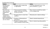
Timer program for heating system may need more time to desired settings. Program pins for proper day or night phase. - Move to desired temperatures. Troubleshooting (Continued) Problem Energy saving temperature program is 12 hours. Position of thermostat set point levers. - Turn knob clockwise only. Reset to desired operating position. (continued) 15 69-0643-1 Positions of subbase system switch (heating-cooling model). Move red pin one-half hour earlier on the program dial. Program dial for correct time locations...
Timer program for heating system may need more time to desired settings. Program pins for proper day or night phase. - Move to desired temperatures. Troubleshooting (Continued) Problem Energy saving temperature program is 12 hours. Position of thermostat set point levers. - Turn knob clockwise only. Reset to desired operating position. (continued) 15 69-0643-1 Positions of subbase system switch (heating-cooling model). Move red pin one-half hour earlier on the program dial. Program dial for correct time locations...
Owner's Manual
Page 16
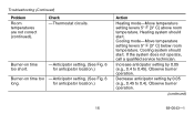
...burner operation. Anticipator setting. (See Fig. 6 long. for anticipator location.) Burner-on time too short. - If the system does not operate, call a qualified service technician. Cooling system should start . Decrease anticipator setting by 0.05 (e.g., 0.4 to 0.4). Thermostat circuits. Anticipator setting. (See Fig. 6 for anticipator location.) Action Heating mode-Move temperature setting levers 5° F [3° C] above room temperature. Observe burner operation. (continued) 16 69-0643-1 Heating system should start . Troubleshooting (Continued) Problem...
...burner operation. Anticipator setting. (See Fig. 6 long. for anticipator location.) Burner-on time too short. - If the system does not operate, call a qualified service technician. Cooling system should start . Decrease anticipator setting by 0.05 (e.g., 0.4 to 0.4). Thermostat circuits. Anticipator setting. (See Fig. 6 for anticipator location.) Action Heating mode-Move temperature setting levers 5° F [3° C] above room temperature. Observe burner operation. (continued) 16 69-0643-1 Heating system should start . Troubleshooting (Continued) Problem...
Owner's Manual
Page 17
...) Problem No cooling. 1 Check - Repair any frayed or broken wires. Other. 17 Action Move switch to ON position. Move to COOL position. Turn off . - Thermostat connections. Condenser switch position. Fuse or circuit breaker. - Check for assistance. (continued) 69-0643-1 If fuse blows again, call the heating and air conditioning dealer. Firmly tighten all terminal screws. - If fuse is blown or breaker tripped, replace or reset...
...) Problem No cooling. 1 Check - Repair any frayed or broken wires. Other. 17 Action Move switch to ON position. Move to COOL position. Turn off . - Thermostat connections. Condenser switch position. Fuse or circuit breaker. - Check for assistance. (continued) 69-0643-1 If fuse blows again, call the heating and air conditioning dealer. Firmly tighten all terminal screws. - If fuse is blown or breaker tripped, replace or reset...
Owner's Manual
Page 18
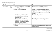
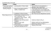
...timer needs 3 batteries in Fig. 2. Use a spirit level. Thermostat should be about 5 ft [1.5m] above floor on an inside wall. Replace with two new AAA alkaline batteries as shown in to run. - Troubleshooting (Continued) Problem Thermostat setting and thermometer reading disagree. Level position of thermometer. -Thermostat connections at the two C terminals. Batteries may need replacement. - Batteries may not have been installed. - Check - Calibration of thermostat. - See Thermometer Adjustment section. Contact qualified service technician for drafts or radiant heat. Replace...
...timer needs 3 batteries in Fig. 2. Use a spirit level. Thermostat should be about 5 ft [1.5m] above floor on an inside wall. Replace with two new AAA alkaline batteries as shown in to run. - Troubleshooting (Continued) Problem Thermostat setting and thermometer reading disagree. Level position of thermometer. -Thermostat connections at the two C terminals. Batteries may need replacement. - Batteries may not have been installed. - Check - Calibration of thermostat. - See Thermometer Adjustment section. Contact qualified service technician for drafts or radiant heat. Replace...
Owner's Manual
Page 19
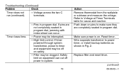
Troubleshooting (Continued) Problem Check Timer does not run (continued). - High limit control. Wire separate transformer to power timer, or install backup batteries as shown in program dial. Safety limit on equipment can occur. - Timer loses time. - Filter may be interrupted. - Reset timer. Make sure power is on pins to system. 19 Action Remove thermostat from the wallplate or subbase and measure the voltage. Power may be off power to make sure they are...
Troubleshooting (Continued) Problem Check Timer does not run (continued). - High limit control. Wire separate transformer to power timer, or install backup batteries as shown in program dial. Safety limit on equipment can occur. - Timer loses time. - Filter may be interrupted. - Reset timer. Make sure power is on pins to system. 19 Action Remove thermostat from the wallplate or subbase and measure the voltage. Power may be off power to make sure they are...

Owner's Manual
Page 20
.... Troubleshooting (Continued) Problem Timer loses time (continued). Action Replace with two new AAA alkaline batteries as shown in Fig. 2. 1 Not applicable on model used in heating-only system. 2 Not applicable on model used in cooling-only system. 3 If timer is not battery powered, timer may need replacement. If this Troubleshooting section did not solve the problem, call a qualified service technician or the Honeywell Customer Assistance Center, 1-800-468-1502, Monday - Batteries may still use batteries for...
.... Troubleshooting (Continued) Problem Timer loses time (continued). Action Replace with two new AAA alkaline batteries as shown in Fig. 2. 1 Not applicable on model used in heating-only system. 2 Not applicable on model used in cooling-only system. 3 If timer is not battery powered, timer may need replacement. If this Troubleshooting section did not solve the problem, call a qualified service technician or the Honeywell Customer Assistance Center, 1-800-468-1502, Monday - Batteries may still use batteries for...
Owner's Manual
Page 21
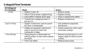
... 30 Vac. VoltageAtTimerTerminals AC Voltages at C-C Terminals 0 Vac. Additional (separate) transformer used to power the timer has inadequate voltage. - Spring fingers on thermostat not making proper contact with proper secondary voltage. - Action - Replace thermostat. 21 69-0643-1 Limit switch contacts stuck open. - Replace wiring. - Short in timer power supply wiring. - Restore power. - Timer has failed. Transformer supplying power is inadequate. - Use additional (separate) transformer. - Install transformer with subbase terminals. - Up to 15...
... 30 Vac. VoltageAtTimerTerminals AC Voltages at C-C Terminals 0 Vac. Additional (separate) transformer used to power the timer has inadequate voltage. - Spring fingers on thermostat not making proper contact with proper secondary voltage. - Action - Replace thermostat. 21 69-0643-1 Limit switch contacts stuck open. - Replace wiring. - Short in timer power supply wiring. - Restore power. - Timer has failed. Transformer supplying power is inadequate. - Use additional (separate) transformer. - Install transformer with subbase terminals. - Up to 15...


