
Specifications
Page 5
... 6.2.5 Addressing of figures xi 1.0 General 1 1.1 Glossary 1 1.2 General caution 1 1.3 References 1 2.0 General features 3 Part 1. Table of contents List of registers 38 6.2.6 Cabling 38 6.3 Jumper settings 39 6.3.1 Jumper pin location 39 6.3.2 Jumper pin identification 39 6.3.3 Jumper pin assignment 40 6.3.4 Jumper positions 41 6.4 Environment 45 6.4.1 Temperature and humidity 45 6.4.2 Corrosion test 46 6.5 DC power requirements 47 Deskstar 180GXP hard disk drive specifications v
... 6.2.5 Addressing of figures xi 1.0 General 1 1.1 Glossary 1 1.2 General caution 1 1.3 References 1 2.0 General features 3 Part 1. Table of contents List of registers 38 6.2.6 Cabling 38 6.3 Jumper settings 39 6.3.1 Jumper pin location 39 6.3.2 Jumper pin identification 39 6.3.3 Jumper pin assignment 40 6.3.4 Jumper positions 41 6.4 Environment 45 6.4.1 Temperature and humidity 45 6.4.2 Corrosion test 46 6.5 DC power requirements 47 Deskstar 180GXP hard disk drive specifications v
Specifications
Page 11
...24. Ultra DMA cycle timing chart (Initiating Read 30 Figure 28. Ultra DMA cycle timing chart (Initiating Write 34 Figure 36. Jumper pin identification (2- List of signals 22 Figure 20. Command overhead 12 Figure 5. Single Track Seek Time 14 Figure 10. Simple Sequential...default 42 Figure 49. Limits of temperature and humidity 46 Deskstar 180GXP hard disk drive specifications xi Power connector pin assignments 21 Figure 19. Jumper positions for normal use 41 Figure 48. Drive ready time 14 Figure 12. Jumper pin assignment 40 Figure 47. Ultra DMA cycle timings ...
...24. Ultra DMA cycle timing chart (Initiating Read 30 Figure 28. Ultra DMA cycle timing chart (Initiating Write 34 Figure 36. Jumper pin identification (2- List of signals 22 Figure 20. Command overhead 12 Figure 5. Single Track Seek Time 14 Figure 10. Simple Sequential...default 42 Figure 49. Limits of temperature and humidity 46 Deskstar 180GXP hard disk drive specifications xi Power connector pin assignments 21 Figure 19. Jumper positions for normal use 41 Figure 48. Drive ready time 14 Figure 12. Jumper pin assignment 40 Figure 47. Ultra DMA cycle timings ...

Specifications
Page 54
...) y 15 logical head default y 2 GB/32 GB clip y Power up in standby Within each of these four jumper settings the pin assignment selects Device 0, Device 1, Cable Selection, or Device 1 Slave Present as shown in the following figures. The Device 1 Slave Present setting is present. Jumper pin assignment Deskstar 180GXP hard disk drive specifications 40 The Device 0 setting...
...) y 15 logical head default y 2 GB/32 GB clip y Power up in standby Within each of these four jumper settings the pin assignment selects Device 0, Device 1, Cable Selection, or Device 1 Slave Present as shown in the following figures. The Device 1 Slave Present setting is present. Jumper pin assignment Deskstar 180GXP hard disk drive specifications 40 The Device 0 setting...

Specifications
Page 55
Deskstar 180GXP hard disk drive specifications 41 To enable the CSEL mode (Cable Selection mode) the jumper block must be installed at a high level, the drive address is 1 (Device 1). 2. The shipping default position is grounded or at A-B or C-D position does not affect any selection of Device or... Cable Selection mode. 3. y When CSEL is 0 (Device 0). In CSEL mode, installing or removing the jumper blocks at a low level, the drive address is open or at E-F. IGECA HFDB IGECA HFDB IGECA HFDB IGECA HFDB IGECA HFDB DEVICE 0 (Master) DEVICE 1 (Slave) CABLE...
Deskstar 180GXP hard disk drive specifications 41 To enable the CSEL mode (Cable Selection mode) the jumper block must be installed at a high level, the drive address is 1 (Device 1). 2. The shipping default position is grounded or at A-B or C-D position does not affect any selection of Device or... Cable Selection mode. 3. y When CSEL is 0 (Device 0). In CSEL mode, installing or removing the jumper blocks at a low level, the drive address is open or at E-F. IGECA HFDB IGECA HFDB IGECA HFDB IGECA HFDB IGECA HFDB DEVICE 0 (Master) DEVICE 1 (Slave) CABLE...

Specifications
Page 56
... of default 16 logical head models. In the CSEL mode, the drive address is determined by AT interface signal #28 CSEL as follows: y When CSEL is 0 (Device 0). Deskstar 180GXP hard disk drive specifications 42 Jumper positions for 15 logical head default Notes: 1. To enable the CSEL... mode (Cable Selection mode) the jumper block must be installed at a high level, the drive address is open or at E-F. 6.3.4.2 15 logical head...
... of default 16 logical head models. In the CSEL mode, the drive address is determined by AT interface signal #28 CSEL as follows: y When CSEL is 0 (Device 0). Deskstar 180GXP hard disk drive specifications 42 Jumper positions for 15 logical head default Notes: 1. To enable the CSEL... mode (Cable Selection mode) the jumper block must be installed at a high level, the drive address is open or at E-F. 6.3.4.2 15 logical head...
Specifications
Page 57
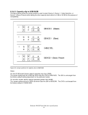
...of compatibility. Deskstar 180GXP hard disk drive specifications 43 I GECA HFDB DEVICE 0 (Master) I GECA HF DB DEVICE 1 (Slave) IGECA HFDB CABLE SEL I GECA HFDB DEVICE 1 (Slave) Present Figure 49. The LBA is unchanged from the factory default setting (dependent on the particular model). Jumper positions for ...Cable Selection, or Device 1 (Slave) Present while setting the drive capacity down either to 2 GB or 32 GB for capacity clip to 2GB/32GB Notes: For the 30-GB model (factory default capacities less than 32GB): The jumper setting acts as a 2GB clip which clips the LBA to 4096...
...of compatibility. Deskstar 180GXP hard disk drive specifications 43 I GECA HFDB DEVICE 0 (Master) I GECA HF DB DEVICE 1 (Slave) IGECA HFDB CABLE SEL I GECA HFDB DEVICE 1 (Slave) Present Figure 49. The LBA is unchanged from the factory default setting (dependent on the particular model). Jumper positions for ...Cable Selection, or Device 1 (Slave) Present while setting the drive capacity down either to 2 GB or 32 GB for capacity clip to 2GB/32GB Notes: For the 30-GB model (factory default capacities less than 32GB): The jumper setting acts as a 2GB clip which clips the LBA to 4096...

Specifications
Page 58
... DEVICE 1 (Slave) Present Figure 50. Command to spin up is 0 (Device 0). Deskstar 180GXP hard disk drive specifications 44 y When CSEL is 1 (Device 1). 6.3.4.4 Power Up In Standby The figure below shows the jumper positions used . 2. Jumper settings for limiting power supply current when multiple drives are used for Disabling Auto Spin Notes: 1. To enable the CSEL mode...
... DEVICE 1 (Slave) Present Figure 50. Command to spin up is 0 (Device 0). Deskstar 180GXP hard disk drive specifications 44 y When CSEL is 1 (Device 1). 6.3.4.4 Power Up In Standby The figure below shows the jumper positions used . 2. Jumper settings for limiting power supply current when multiple drives are used for Disabling Auto Spin Notes: 1. To enable the CSEL mode...

Specifications
Page 72
.../CE/C-Tick mark logos A bar code label containing the drive serial number A label containing the jumper pin description A user designed label per agreement The above labels may be integrated with the appropriate hard disk drive assembly drawing: A label containing the IBM logo, the... IBM part number, and the statement "Made by IBM Japan Ltd." 6.10 Identification labels The following labels are affixed to every drive shipped from the drive manufacturing location in accordance with other labels. Deskstar 180GXP hard disk drive...
.../CE/C-Tick mark logos A bar code label containing the drive serial number A label containing the jumper pin description A user designed label per agreement The above labels may be integrated with the appropriate hard disk drive assembly drawing: A label containing the IBM logo, the... IBM part number, and the statement "Made by IBM Japan Ltd." 6.10 Identification labels The following labels are affixed to every drive shipped from the drive manufacturing location in accordance with other labels. Deskstar 180GXP hard disk drive...

Specifications
Page 104
...spin-up of a jumper. The device remains in detail. Device power consumption may increase with increasing advanced power management levels. This feature set and times out 2. The Standby timer has been set uses the following are independent functions. Deskstar 180GXP hard disk drive specifications 90 Device ...device shall set word 0 bit 2 to one to active state when the device has powered up into Standby. When enabled by a jumper, the feature set . The IDENTIFY DEVICE information indicates the states as a result of 01h to select an advanced power management level. The...
...spin-up of a jumper. The device remains in detail. Device power consumption may increase with increasing advanced power management levels. This feature set and times out 2. The Standby timer has been set uses the following are independent functions. Deskstar 180GXP hard disk drive specifications 90 Device ...device shall set word 0 bit 2 to one to active state when the device has powered up into Standby. When enabled by a jumper, the feature set . The IDENTIFY DEVICE information indicates the states as a result of 01h to select an advanced power management level. The...

Specifications
Page 139
...status 1= Above Vih 0= Below Vil 12- 8 Dev 1 H/W reset result 12 Reserved 11 PDIAG- Identify Device Information (part 5 of 6) Deskstar 180GXP hard disk drive specifications 125 Word Content 88 0X3FH 89 XXXXH 90 0000H 91 0000H 92 FFFEH 93 XXXXH 94 XXXXH Description Ultra DMA transfer modes 15- 8 (=xx...Password Revision Code Hardware reset result. assertion 1= assert 0= not assert 10- 9 How to determine the device number 00=Reserved 01=Jumper 10=CSEL signal 11=Some other method 0 Shall be set to one if Dev 0 Current Advanced Power Management value 15- 8 ...
...status 1= Above Vih 0= Below Vil 12- 8 Dev 1 H/W reset result 12 Reserved 11 PDIAG- Identify Device Information (part 5 of 6) Deskstar 180GXP hard disk drive specifications 125 Word Content 88 0X3FH 89 XXXXH 90 0000H 91 0000H 92 FFFEH 93 XXXXH 94 XXXXH Description Ultra DMA transfer modes 15- 8 (=xx...Password Revision Code Hardware reset result. assertion 1= assert 0= not assert 10- 9 How to determine the device number 00=Reserved 01=Jumper 10=CSEL signal 11=Some other method 0 Shall be set to one if Dev 0 Current Advanced Power Management value 15- 8 ...

Specifications
Page 245
..., 21 Automatic Acoustic Management, 91 Average latency, 14 C Cable noise interference, 50 Cabling, 38 CE Mark, 60 Command descriptions, 105 Command overhead, 12 Command Protocol, 95 Commands, 84 Connector locations, 54 Control Electronics, 7 CSA standard conformity, 59...Jumper pin assignment, 40 Jumper positions, 41 Jumper settings, 39 L Labels, 58 LBA Addressing Mode, 74 Logical CHS Addressing Mode, 74 M Mechanical positioning, 12 Mechanical specifications, 51 Mode transition time, 17 N Non-data commands, 100 O Operating conditions, 45 Operating mode definition, 17 Deskstar 180GXP hard disk drive...
..., 21 Automatic Acoustic Management, 91 Average latency, 14 C Cable noise interference, 50 Cabling, 38 CE Mark, 60 Command descriptions, 105 Command overhead, 12 Command Protocol, 95 Commands, 84 Connector locations, 54 Control Electronics, 7 CSA standard conformity, 59...Jumper pin assignment, 40 Jumper positions, 41 Jumper settings, 39 L Labels, 58 LBA Addressing Mode, 74 Logical CHS Addressing Mode, 74 M Mechanical positioning, 12 Mechanical specifications, 51 Mode transition time, 17 N Non-data commands, 100 O Operating conditions, 45 Operating mode definition, 17 Deskstar 180GXP hard disk drive...


