Instruction Manual
Page 13
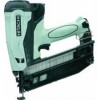
NAME OF PARTS 1. Gas Finish Nailer Top cover Actuator Chamber Handle Top cover Chamber Actuator Handle Battery Piston Driver blade Trigger Battery Hook Piston Driver blade Trigger Firing head (outlet) Magazine ... information contained in this Manual is designed to assist you in this Manual may show details or attachments that differ from those on your own Nailer. Some illustrations in the safe operation of the...
NAME OF PARTS 1. Gas Finish Nailer Top cover Actuator Chamber Handle Top cover Chamber Actuator Handle Battery Piston Driver blade Trigger Battery Hook Piston Driver blade Trigger Firing head (outlet) Magazine ... information contained in this Manual is designed to assist you in this Manual may show details or attachments that differ from those on your own Nailer. Some illustrations in the safe operation of the...
Instruction Manual
Page 15
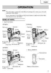
Gas Brad Nailer Model Dimensions Length × Height × Width Weight Includes battery and fuel cell Nail capacity Cycle rate Battery Fuel Cell NT50GS 10-5/8" × 11-1/8" × 3-3/8" (... DC 1.5 A 0.4 lbs (0.2 kg) NOTE: The charging time may vary according to temperature and power source voltage. 15 Gas Finish Nailer Model Dimensions Length × Height × Width Weight Includes battery and fuel cell Nail capacity Cycle rate Battery Fuel Cell NT65GS NT65GB NT65GA 10-1/4" × 11" × 3-3/8" 10-5/8" × 11-1/8" × 3-3/8" 12" × 12" × 5" (260...
Gas Brad Nailer Model Dimensions Length × Height × Width Weight Includes battery and fuel cell Nail capacity Cycle rate Battery Fuel Cell NT50GS 10-5/8" × 11-1/8" × 3-3/8" (... DC 1.5 A 0.4 lbs (0.2 kg) NOTE: The charging time may vary according to temperature and power source voltage. 15 Gas Finish Nailer Model Dimensions Length × Height × Width Weight Includes battery and fuel cell Nail capacity Cycle rate Battery Fuel Cell NT65GS NT65GB NT65GA 10-1/4" × 11" × 3-3/8" 10-5/8" × 11-1/8" × 3-3/8" 12" × 12" × 5" (260...
Instruction Manual
Page 16
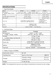
...and/or nail breakdown, leading to use of nails 16 Gauge finish nails (straight) Min. .110" (2.8mm) Max. 2-1/2" (65mm) 1" (25mm) .051" (1.3mm) .055" (1.4mm) .065" (1.65mm) 16 Gauge finish nails (Angle: 20°) Min. .110" (2.8mm) Max. 2-1/2"... (65mm) 1-1/4" (32mm) .051" (1.3mm) .055" (1.4mm) .065" (1.65mm) 16 English NAIL SELECTION WARNING ⅷ Be sure to serious injuries. Dimensions of any other nails can be driven with this Nailer. The use only the genuine HITACHI nails for the NT65GS, NT65GB, NT65GA...
...and/or nail breakdown, leading to use of nails 16 Gauge finish nails (straight) Min. .110" (2.8mm) Max. 2-1/2" (65mm) 1" (25mm) .051" (1.3mm) .055" (1.4mm) .065" (1.65mm) 16 Gauge finish nails (Angle: 20°) Min. .110" (2.8mm) Max. 2-1/2"... (65mm) 1-1/4" (32mm) .051" (1.3mm) .055" (1.4mm) .065" (1.65mm) 16 English NAIL SELECTION WARNING ⅷ Be sure to serious injuries. Dimensions of any other nails can be driven with this Nailer. The use only the genuine HITACHI nails for the NT65GS, NT65GB, NT65GA...
Instruction Manual
Page 24
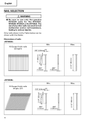
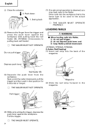
...feeder (B). (NT50GS: Unnecessary to be used in the actual application. Ⅺ THE NAILER MUST OPERATE PROPERLY. (4) Remove the finger from the workpiece. and 3) keep Nailer pointed downward. 2-Action Nail Feeding! (1) Insert nail strip into Nailer, 1) do not pull trigger; 2) do not depress push lever; Next, point...load nails in the magazine. Swing back (7) If no abnormal operation is the same type to pulling back nail feeder) Ⅺ THE NAILER MUST NOT OPERATE. Depress push lever Nail feeder (B) (5) Separate the push lever from the trigger and press the push lever against the ...
...feeder (B). (NT50GS: Unnecessary to be used in the actual application. Ⅺ THE NAILER MUST OPERATE PROPERLY. (4) Remove the finger from the workpiece. and 3) keep Nailer pointed downward. 2-Action Nail Feeding! (1) Insert nail strip into Nailer, 1) do not pull trigger; 2) do not depress push lever; Next, point...load nails in the magazine. Swing back (7) If no abnormal operation is the same type to pulling back nail feeder) Ⅺ THE NAILER MUST NOT OPERATE. Depress push lever Nail feeder (B) (5) Separate the push lever from the trigger and press the push lever against the ...

Instruction Manual
Page 27
...workpiece with Nailer at the same time. To continue nailing in a separate location, move the nailer along ...drive nails from Nailer when: 1) it is not in spattering. NT65GS, NT65GA, NT65GB employ a preventive...NT65GS, NT65GA, NT65GB enter a state where the push lever cannot be driven. This Nailer is ...fastener. English ⅷ Do not use Nailer as required. 3 2 Push lever Trigger... careful of nails becomes less than 8 inches (200 mm) from the trigger. It is intermittent...Nailer which is defective or operating abnormally. ⅷ Do not use the electrical cord if damaged. This Nailer...
...workpiece with Nailer at the same time. To continue nailing in a separate location, move the nailer along ...drive nails from Nailer when: 1) it is not in spattering. NT65GS, NT65GA, NT65GB employ a preventive...NT65GS, NT65GA, NT65GB enter a state where the push lever cannot be driven. This Nailer is ...fastener. English ⅷ Do not use Nailer as required. 3 2 Push lever Trigger... careful of nails becomes less than 8 inches (200 mm) from the trigger. It is intermittent...Nailer which is defective or operating abnormally. ⅷ Do not use the electrical cord if damaged. This Nailer...
Instruction Manual
Page 29
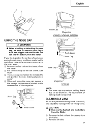
... to the toe of the push lever. 3 The nose cap is marked to the push lever. 1 Remove the fuel cell and the battery from the Nailer. 2 Remove all nails. 29 CLEARING A JAM If nails are jammed in firing head, remove it, and adjust the nailing in the storage compartment located on... the reverse side of nailing depth is required. English Nose Cap Magazine NT65GS, NT65GA, NT65GB USING THE NOSE CAP WARNING ⅷ When attaching or detaching the nose cap, be sure to its thickness. Nose Cap Push Lever Nose Cap Nose...
... to the toe of the push lever. 3 The nose cap is marked to the push lever. 1 Remove the fuel cell and the battery from the Nailer. 2 Remove all nails. 29 CLEARING A JAM If nails are jammed in firing head, remove it, and adjust the nailing in the storage compartment located on... the reverse side of nailing depth is required. English Nose Cap Magazine NT65GS, NT65GA, NT65GB USING THE NOSE CAP WARNING ⅷ When attaching or detaching the nose cap, be sure to its thickness. Nose Cap Push Lever Nose Cap Nose...
Instruction Manual
Page 107
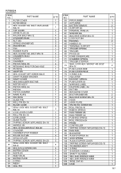
... PIN D3×10 37 LOCK LEVER 38 GUIDE PLATE 39 TAPPING SCREW (W/FLANGE) D4×16 40 HANDLE (B) 41 HEX. SOCKET HD. NT65GA ITEM NO. PART NAME 1 FILTER COVER 2 FILTER MESH 3 HEX. BOLT (W/FLANGE) M5×10 4 TOP COVER 5 SPARK PLUG (A) ...1 1 1 4 1 2 2 2 1 1 4 1 1 1 4 1 1 1 2 1 1 2 1 2 1 1 1 1 1 2 1 3 1 1 1 1 2 1 1 1 1 3 1 2 4 4 1 1 1 1 1 1 1 ITEM NO. SHOULDER BOLT M4×32 42 CYLINDER 43 CHAMBER STOP RUBBER 44 NYLON NUT M5 45 HITACHI PLATE 46 TAPPING SCREW (W/FLANGE) D4×20 47 SEAL LOCK HEX. BOLT M4×16 14 CHAMBER HEAD 15 GASKET 16 CHAMBER 17 PISTON...
... PIN D3×10 37 LOCK LEVER 38 GUIDE PLATE 39 TAPPING SCREW (W/FLANGE) D4×16 40 HANDLE (B) 41 HEX. SOCKET HD. NT65GA ITEM NO. PART NAME 1 FILTER COVER 2 FILTER MESH 3 HEX. BOLT (W/FLANGE) M5×10 4 TOP COVER 5 SPARK PLUG (A) ...1 1 1 4 1 2 2 2 1 1 4 1 1 1 4 1 1 1 2 1 1 2 1 2 1 1 1 1 1 2 1 3 1 1 1 1 2 1 1 1 1 3 1 2 4 4 1 1 1 1 1 1 1 ITEM NO. SHOULDER BOLT M4×32 42 CYLINDER 43 CHAMBER STOP RUBBER 44 NYLON NUT M5 45 HITACHI PLATE 46 TAPPING SCREW (W/FLANGE) D4×20 47 SEAL LOCK HEX. BOLT M4×16 14 CHAMBER HEAD 15 GASKET 16 CHAMBER 17 PISTON...

