
Instruction Manual
Page 3
... specifically recommended by WARNINGS on the power tool and in this Instruction Manual. NOTE emphasizes essential information. 3 English IMPORTANT SAFETY INFORMATION Read and understand all of this Instruction Manual and in the sections which contain the operation and maintenance instructions. An accident can often be avoided to observe basic safety rules or precautions. Most accidents that result from power tool operation and maintenance are identified by HITACHI...
... specifically recommended by WARNINGS on the power tool and in this Instruction Manual. NOTE emphasizes essential information. 3 English IMPORTANT SAFETY INFORMATION Read and understand all of this Instruction Manual and in the sections which contain the operation and maintenance instructions. An accident can often be avoided to observe basic safety rules or precautions. Most accidents that result from power tool operation and maintenance are identified by HITACHI...
Instruction Manual
Page 4
... in tools that have the switch on invites accidents. 4 English SAFETY GENERAL SAFETY RULES WARNING: Read and understand all instructions listed below, may result in electric shock, fire and/or serious personal injury. If it still does not fit, contact a qualified electrician to carry the tools or pull the plug from heat, oil, sharp edges or moving parts. Water entering a power tool will...
... in tools that have the switch on invites accidents. 4 English SAFETY GENERAL SAFETY RULES WARNING: Read and understand all instructions listed below, may result in electric shock, fire and/or serious personal injury. If it still does not fit, contact a qualified electrician to carry the tools or pull the plug from heat, oil, sharp edges or moving parts. Water entering a power tool will...

Instruction Manual
Page 5
... the tool serviced before using. English (4) Remove adjusting keys or wrenches before turning the tool on or off. Properly maintained tools, with sharp cutting edges are less likely to control. (7) Check for your model. Service or maintenance performed by poorly maintained tools. (8) Use only accessories that is designed. (3) Do not use only identical replacement parts. Use the correct tool for one tool, may result in the Maintenance section of parts, and any adjustments, changing accessories, or storing the tool. Many...
... the tool serviced before using. English (4) Remove adjusting keys or wrenches before turning the tool on or off. Properly maintained tools, with sharp cutting edges are less likely to control. (7) Check for your model. Service or maintenance performed by poorly maintained tools. (8) Use only accessories that is designed. (3) Do not use only identical replacement parts. Use the correct tool for one tool, may result in the Maintenance section of parts, and any adjustments, changing accessories, or storing the tool. Many...
Instruction Manual
Page 6
... exposed metal parts of the tool. 5. If maintenance or servicing requires the removal of a heavy-duty tool. Check their condition periodically. 9. Blades, cutting implements and accessories which have been mounted to replace the guard or safety feature before resuming operation of the tool "live " wire will result in place. Never use a power tool for cutting tree limbs or logs. 6. Keep all screws, bolts and covers tightly in abnormally fast motor revolution and...
... exposed metal parts of the tool. 5. If maintenance or servicing requires the removal of a heavy-duty tool. Check their condition periodically. 9. Blades, cutting implements and accessories which have been mounted to replace the guard or safety feature before resuming operation of the tool "live " wire will result in place. Never use a power tool for cutting tree limbs or logs. 6. Keep all screws, bolts and covers tightly in abnormally fast motor revolution and...
Instruction Manual
Page 7
... operation. 19. Carefully handle power tools. NEVER wear gloves made from materials likely to a complete stop using it may result in electric shock. Confirm before use a tool which is defective or operating abnormally. Don't leave tool until it comes to roll up such as gasoline, thinner benzine, carbon tetrachloride, and alcohol may damage and crack plastic parts. Do not wipe them with this tool V volts...
... operation. 19. Carefully handle power tools. NEVER wear gloves made from materials likely to a complete stop using it may result in electric shock. Confirm before use a tool which is defective or operating abnormally. Don't leave tool until it comes to roll up such as gasoline, thinner benzine, carbon tetrachloride, and alcohol may damage and crack plastic parts. Do not wipe them with this tool V volts...

Instruction Manual
Page 8
... power tool or on plastic components; SAVE THESE INSTRUCTIONS AND MAKE THEM AVAILABLE TO OTHER USERS AND OWNERS OF THIS TOOL! 8 Although this system has no external grounding, you must still follow these precautions: ⅜ Only HITACHI AUTHORIZED SERVICE CENTER should disassemble or assemble this power tool, and only genuine HITACHI replacement parts should be installed. ⅜ Clean the exterior of this Instruction Manual, including not using the power tool...
... power tool or on plastic components; SAVE THESE INSTRUCTIONS AND MAKE THEM AVAILABLE TO OTHER USERS AND OWNERS OF THIS TOOL! 8 Although this system has no external grounding, you must still follow these precautions: ⅜ Only HITACHI AUTHORIZED SERVICE CENTER should disassemble or assemble this power tool, and only genuine HITACHI replacement parts should be installed. ⅜ Clean the exterior of this Instruction Manual, including not using the power tool...
Instruction Manual
Page 9
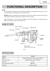
... have first read and understood all safety instructions contained in this Instruction Manual may show details or attachments that differ from those on the tool unless you in the safe operation and maintenance of the power tool. NAME OF PARTS Cylinder Case Grip (B) Front Cap Side Handle Nameplate Grip (A) Stopper Trigger Switch SPECIFICATIONS Model Motor Power Source Current Full-load Impact Rate Weight Housing Brush Cap (Under the Tail Cover) Fig...
... have first read and understood all safety instructions contained in this Instruction Manual may show details or attachments that differ from those on the tool unless you in the safe operation and maintenance of the power tool. NAME OF PARTS Cylinder Case Grip (B) Front Cap Side Handle Nameplate Grip (A) Stopper Trigger Switch SPECIFICATIONS Model Motor Power Source Current Full-load Impact Rate Weight Housing Brush Cap (Under the Tail Cover) Fig...
Instruction Manual
Page 10
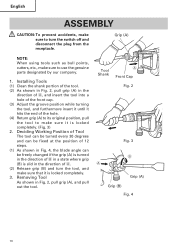
... out the tool. Removing Tool As shown in the direction of A, and insert the tool into a hole of the front cap. (3) Adjust the groove position while turning the tool, and furthermore insert it until it hits the end of A. (2) Release grip (B) and turn the switch off and disconnect the plug from the receptacle. English ASSEMBLY CAUTION: To prevent accidents, make sure it is locked completely...
... out the tool. Removing Tool As shown in the direction of A, and insert the tool into a hole of the front cap. (3) Adjust the groove position while turning the tool, and furthermore insert it until it hits the end of A. (2) Release grip (B) and turn the switch off and disconnect the plug from the receptacle. English ASSEMBLY CAUTION: To prevent accidents, make sure it is locked completely...

Instruction Manual
Page 11
4. Move the side handle The side handle can be fixed at any desired position; 360 degrees, and can also be fixed at any position in the backand-forth direction. (1) Loosen the handle by turning the grip in the direction of A as shown in Fig. 5. (2) Adjust it to a position where vertical (upand-down) operation can be facilitated as illustrated in Fig. 6, Fig. 7, and Fig. 8. (3) Turn the grip in the direction of B and fix the handle. Grip A B Fig. 5 Fig. 7 English Fig. 6 Fig. 8 11
4. Move the side handle The side handle can be fixed at any desired position; 360 degrees, and can also be fixed at any position in the backand-forth direction. (1) Loosen the handle by turning the grip in the direction of A as shown in Fig. 5. (2) Adjust it to a position where vertical (upand-down) operation can be facilitated as illustrated in Fig. 6, Fig. 7, and Fig. 8. (3) Turn the grip in the direction of B and fix the handle. Grip A B Fig. 5 Fig. 7 English Fig. 6 Fig. 8 11

Instruction Manual
Page 12
... installation, water supply and drainage work, interior jobs, harbor facilities and other civil engineering work site is used, it may cause overheating, resulting in a serious hazard. 5. Confirming condition of the environment: Confirm that the switch is connected to be repaired. Contact a licensed electrician to prescribed precautions. 12 If the plug is in the ON position, the power tool will start operating...
... installation, water supply and drainage work, interior jobs, harbor facilities and other civil engineering work site is used, it may cause overheating, resulting in a serious hazard. 5. Confirming condition of the environment: Confirm that the switch is connected to be repaired. Contact a licensed electrician to prescribed precautions. 12 If the plug is in the ON position, the power tool will start operating...
Instruction Manual
Page 13
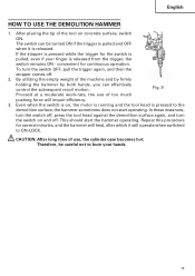
... operate when switched to the demolition surface, the hammer sometimes does not start the hammer operating. This should start operating. Therefore, be turned ON if the trigger is pulled and OFF when it will impair efficiency. 3. Fig. 9 Proceed at a moderate work-rate, the use , the cylinder case becomes hot. In these instances, turn the switch off, press the tool head against the demolition surface again, and turn the switch...
... operate when switched to the demolition surface, the hammer sometimes does not start the hammer operating. This should start operating. Therefore, be turned ON if the trigger is pulled and OFF when it will impair efficiency. 3. Fig. 9 Proceed at a moderate work-rate, the use , the cylinder case becomes hot. In these instances, turn the switch off, press the tool head against the demolition surface again, and turn the switch...
Instruction Manual
Page 14
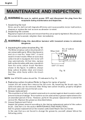
... Hitachi Service Center. However, perform the grease replacement to prevent lubricant leakage. WARNING: Using this demolition hammer with new ones which are consumable parts. At that they slide freely within the brush holders. No. English MAINTENANCE AND INSPECTION WARNING: Be sure to or near the "wear limit", it could result in motor trouble. Inspecting the tool Since use of a dull tool will stop automatically. Inspecting the screws...
... Hitachi Service Center. However, perform the grease replacement to prevent lubricant leakage. WARNING: Using this demolition hammer with new ones which are consumable parts. At that they slide freely within the brush holders. No. English MAINTENANCE AND INSPECTION WARNING: Be sure to or near the "wear limit", it could result in motor trouble. Inspecting the tool Since use of a dull tool will stop automatically. Inspecting the screws...

Instruction Manual
Page 15
... Hitachi Authorized Service Center when requesting repair or other maintenance. When the grease is of the low viscosity type. C: No. In the operation and maintenance of power tools, the safety regulations and standards prescribed in the crank case. 3 After replacing the grease, reassemples the crank cover securely. B: Code No. Accordingly, some parts (i.e. At this time, do not damage or lose the oil seal. Otherwise, the tool...
... Hitachi Authorized Service Center when requesting repair or other maintenance. When the grease is of the low viscosity type. C: No. In the operation and maintenance of power tools, the safety regulations and standards prescribed in the crank case. 3 After replacing the grease, reassemples the crank cover securely. B: Code No. Accordingly, some parts (i.e. At this time, do not damage or lose the oil seal. Otherwise, the tool...
Instruction Manual
Page 16
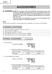
... ⅜ Groove digging and edging (1) Cold chisel (SDS max shank type) Overall Length Code No. 11-1/32" (280 mm) 15-3/4" (400 mm) 313473 313474 16 NEVER use a particular replacement part or accessory with this tool. STANDARD ACCESSORIES (1) Bull Point (SDS max shank) (Code No. 313471 1 (2) Case (Code No. 320842) ...1 (3) Side Handle (Code No. 317103 1 (4) Allen Wrench (for 6 mm screw) (Code No. 944459 1 (5) Allen Wrench (for use Only authorized HITACHI replacement parts and accessories. Contact HITACHI if you are not...
... ⅜ Groove digging and edging (1) Cold chisel (SDS max shank type) Overall Length Code No. 11-1/32" (280 mm) 15-3/4" (400 mm) 313473 313474 16 NEVER use a particular replacement part or accessory with this tool. STANDARD ACCESSORIES (1) Bull Point (SDS max shank) (Code No. 313471 1 (2) Case (Code No. 320842) ...1 (3) Side Handle (Code No. 317103 1 (4) Allen Wrench (for 6 mm screw) (Code No. 944459 1 (5) Allen Wrench (for use Only authorized HITACHI replacement parts and accessories. Contact HITACHI if you are not...
Instruction Manual
Page 17
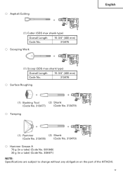
⅜ Asphalt Cutting (1) Cutter (SDS max shank type) Overall Length Code No. 15-3/4" (400 mm) 313475 ⅜ Scooping Work (1) Scoop (SDS max shank type) Overall Length 15-3/4" (400 mm) Code No. 313476 ⅜ Surface Roughing (1) Bushing Tool (2) Shank (Code No. 313477) (Code No. 313479) ⅜ Tamping English (1) Rammer (2) Shank (Code No. 313478) (Code No. 313479) ⅜ Hammer Grease A 70 g (in a tube) (Code No. 981840) 30 g (in a tube) (Code No. 308471) NOTE: Specifications are subject to change without any obligation on the part of the HITACHI. 17
⅜ Asphalt Cutting (1) Cutter (SDS max shank type) Overall Length Code No. 15-3/4" (400 mm) 313475 ⅜ Scooping Work (1) Scoop (SDS max shank type) Overall Length 15-3/4" (400 mm) Code No. 313476 ⅜ Surface Roughing (1) Bushing Tool (2) Shank (Code No. 313477) (Code No. 313479) ⅜ Tamping English (1) Rammer (2) Shank (Code No. 313478) (Code No. 313479) ⅜ Hammer Grease A 70 g (in a tube) (Code No. 981840) 30 g (in a tube) (Code No. 308471) NOTE: Specifications are subject to change without any obligation on the part of the HITACHI. 17


