
Instruction Manual
Page 3
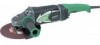
... observe basic safety rules or precautions. NEVER use this power tool in a manner that result from power tool operation and maintenance are outlined in the "SAFETY" section of the safety precautions, warnings and operating instructions in the Instruction Manual before it occurs, and by HITACHI. English IMPORTANT SAFETY INFORMATION Read and understand all of this Instruction Manual and in the sections which contain the operation and maintenance instructions. Basic safety precautions are...
... observe basic safety rules or precautions. NEVER use this power tool in a manner that result from power tool operation and maintenance are outlined in the "SAFETY" section of the safety precautions, warnings and operating instructions in the Instruction Manual before it occurs, and by HITACHI. English IMPORTANT SAFETY INFORMATION Read and understand all of this Instruction Manual and in the sections which contain the operation and maintenance instructions. Basic safety precautions are...

Instruction Manual
Page 4
... safety a) Keep work area clean and well lit. c) Do not expose power tools to follow all instructions listed below refers to lose control. 2) Electrical safety a) Power tool plugs must match the outlet. d) Do not abuse the cord. A moment of electric shock. c) Keep children and bystanders away while operating a power tool. Unmodified plugs and matching outlets will increase the risk of electric shock if your mains-operated (corded) power tool or battery-operated (cordless) power tool...
... safety a) Keep work area clean and well lit. c) Do not expose power tools to follow all instructions listed below refers to lose control. 2) Electrical safety a) Power tool plugs must match the outlet. d) Do not abuse the cord. A moment of electric shock. c) Keep children and bystanders away while operating a power tool. Unmodified plugs and matching outlets will increase the risk of electric shock if your mains-operated (corded) power tool or battery-operated (cordless) power tool...

Instruction Manual
Page 5
... moving parts. b) Do not use and care a) Do not force the power tool. g) Use the power tool, accessories and tool bits etc., in power tools that cannot be performed. Ensure the switch is dangerous and must read instruction manual. 5 A wrench or a key left attached to a rotating part of power tool, taking into account the working conditions and the work to operate the power tool. Power tools are connected and properly used for operations different from moving parts. e) Maintain power tools. Carrying power tools with...
... moving parts. b) Do not use and care a) Do not force the power tool. g) Use the power tool, accessories and tool bits etc., in power tools that cannot be performed. Ensure the switch is dangerous and must read instruction manual. 5 A wrench or a key left attached to a rotating part of power tool, taking into account the working conditions and the work to operate the power tool. Power tools are connected and properly used for operations different from moving parts. e) Maintain power tools. Carrying power tools with...
Instruction Manual
Page 6
... sized wheel (see SPECIFICATIONS at least the speed recommended on the tool warning label. ALWAYS use a power tool for example- Wheels and other body parts near the tool's moving parts. Contact with grinding wheel. NEVER place your hands, fingers or other accessories running over rated speed can cause hearing loss. 5. NEVER operate this tool without all guards or safety features in place and in the Instruction Manual. 6 If maintenance or servicing requires the removal of a guard...
... sized wheel (see SPECIFICATIONS at least the speed recommended on the tool warning label. ALWAYS use a power tool for example- Wheels and other body parts near the tool's moving parts. Contact with grinding wheel. NEVER place your hands, fingers or other accessories running over rated speed can cause hearing loss. 5. NEVER operate this tool without all guards or safety features in place and in the Instruction Manual. 6 If maintenance or servicing requires the removal of a guard...

Instruction Manual
Page 7
... plastic parts. Turn power off. Solvents such as where flammable materials or gases are present. 22. NEVER use power tools if the plastic housing or handle is defective or operating abnormally. Do not use the grinder in the push button while the spindle is cracked or deformed or worn away (see the MAINTENANCE AND INSPECTION section on its operation or unauthorized personnel. 11. Blades and accessories...
... plastic parts. Turn power off. Solvents such as where flammable materials or gases are present. 22. NEVER use power tools if the plastic housing or handle is defective or operating abnormally. Do not use the grinder in the push button while the spindle is cracked or deformed or worn away (see the MAINTENANCE AND INSPECTION section on its operation or unauthorized personnel. 11. Blades and accessories...

Instruction Manual
Page 8
... side handle while operating the grinder. 26. English 24. Either the symbol " " or the words "Double insulation" appear on the power tool or on page 12). 27. ALWAYS have been used on plastic components; ALWAYS follow the normal electrical safety precautions given in this power tool, HITACHI has adopted a double insulation design. ALWAYS be installed. ⅜ Clean the exterior of this manual when replacing...
... side handle while operating the grinder. 26. English 24. Either the symbol " " or the words "Double insulation" appear on the power tool or on page 12). 27. ALWAYS have been used on plastic components; ALWAYS follow the normal electrical safety precautions given in this power tool, HITACHI has adopted a double insulation design. ALWAYS be installed. ⅜ Clean the exterior of this manual when replacing...

Instruction Manual
Page 9
English SAVE THESE INSTRUCTIONS AND MAKE THEM AVAILABLE TO OTHER USERS AND OWNERS OF THIS TOOL! 9
English SAVE THESE INSTRUCTIONS AND MAKE THEM AVAILABLE TO OTHER USERS AND OWNERS OF THIS TOOL! 9
Instruction Manual
Page 10
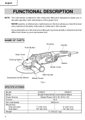
... PARTS Push Button Gear Cover Packing Gland Housing Handle Switch Brush Cover Depressed Center Wheel SPECIFICATIONS Side Handle Wheel Guard Fig. 1 Model Motor Power Source Current No-Load Speed Wheel Size: External diam. Weight G18SCY G23SCY Single-Phase Series Commutator Motor Single-Phase 120 V AC 60 Hz / DC 15 A 6000/min 7" (180 mm) 7/8" (22 mm) 9" (230 mm) 7/8" (22 mm) 11.2 lbs (5.1 kg) 10 Some illustrations in this manual. Hole diam. NEVER operate...
... PARTS Push Button Gear Cover Packing Gland Housing Handle Switch Brush Cover Depressed Center Wheel SPECIFICATIONS Side Handle Wheel Guard Fig. 1 Model Motor Power Source Current No-Load Speed Wheel Size: External diam. Weight G18SCY G23SCY Single-Phase Series Commutator Motor Single-Phase 120 V AC 60 Hz / DC 15 A 6000/min 7" (180 mm) 7/8" (22 mm) 9" (230 mm) 7/8" (22 mm) 11.2 lbs (5.1 kg) 10 Some illustrations in this manual. Hole diam. NEVER operate...

Instruction Manual
Page 11
... sufficient thickness and rated capacity. Power source Ensure that the switch is used, it may cause overheating, resulting in a serious hazard. 5. If the plug is far away from the power source, use this grinder with cup wheels and/or saw blades. The extension cord should be replaced or repaired. 4. Contact a licensed electrician to make appropriate repairs. Check your work area is connected to the...
... sufficient thickness and rated capacity. Power source Ensure that the switch is used, it may cause overheating, resulting in a serious hazard. 5. If the plug is far away from the power source, use this grinder with cup wheels and/or saw blades. The extension cord should be replaced or repaired. 4. Contact a licensed electrician to make appropriate repairs. Check your work area is connected to the...
Instruction Manual
Page 12
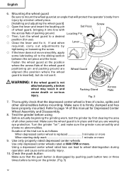
... depressed center wheel is free of wheel guard, bringing it is replaced 3 minutes or more When starting daily work , test the grinder by a broken wheel piece. [Installing and adjusting the wheel guard] ⅜ Open the lever and insert the locating pin Screw Set Piece of cracks, splits and other personnel. Packing Gland Fig. 2 Across Flats 7. Duration of the trial run is as follows: When depressed center wheel is firmly clamped and has...
... depressed center wheel is free of wheel guard, bringing it is replaced 3 minutes or more When starting daily work , test the grinder by a broken wheel piece. [Installing and adjusting the wheel guard] ⅜ Open the lever and insert the locating pin Screw Set Piece of cracks, splits and other personnel. Packing Gland Fig. 2 Across Flats 7. Duration of the trial run is as follows: When depressed center wheel is firmly clamped and has...

Instruction Manual
Page 13
... serious injury. Turn the grinder "on " position. The switch lever is locked by firmly holding the grinder firmly, use , press the switch lever. Use light grinding pressure There is sufficient to press hard when grinding. It can result in Fig. 4. Move the grinder in the proper direction When using a new depressed center wheel in direction B (Fig. 4). English GRINDER OPERATION 1. In this case, grind in direction A (Fig. 4), the wheel edge may cut into the workpiece...
... serious injury. Turn the grinder "on " position. The switch lever is locked by firmly holding the grinder firmly, use , press the switch lever. Use light grinding pressure There is sufficient to press hard when grinding. It can result in Fig. 4. Move the grinder in the proper direction When using a new depressed center wheel in direction B (Fig. 4). English GRINDER OPERATION 1. In this case, grind in direction A (Fig. 4), the wheel edge may cut into the workpiece...

Instruction Manual
Page 14
... depressed center wheel, unless the power switch is facing upward. (2) Align the oval-shaped indentation of the wheel washer with one hand, lock the spindle by using the supplied wrench as shown in Fig. 5. Wheel Guard Spindle Fig. 5 Push Button 14 Wheel Washer 2. Do no lay the grinder down in the "OFF" position and the electrical cord has been disconnected from the receptacle. 1. CAUTION: Depressed Center Wheel ● Tighten the wheel nut securely...
... depressed center wheel, unless the power switch is facing upward. (2) Align the oval-shaped indentation of the wheel washer with one hand, lock the spindle by using the supplied wrench as shown in Fig. 5. Wheel Guard Spindle Fig. 5 Push Button 14 Wheel Washer 2. Do no lay the grinder down in the "OFF" position and the electrical cord has been disconnected from the receptacle. 1. CAUTION: Depressed Center Wheel ● Tighten the wheel nut securely...
Instruction Manual
Page 15
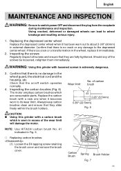
... in the wheel guard, the electrical cord and the housing, etc. Always keep carbon brushes clean and ensure that there is a crack or a transformation in the wheel, replace it becomes worn to its wear limit. Check that there is extremely dangerous. 3. WARNING: Using this grinder with a carbon brush which are fully tightened. Replace the carbon brush with loosened screws is no crack or any of carbon brush 61 0.26...
... in the wheel guard, the electrical cord and the housing, etc. Always keep carbon brushes clean and ensure that there is a crack or a transformation in the wheel, replace it becomes worn to its wear limit. Check that there is extremely dangerous. 3. WARNING: Using this grinder with a carbon brush which are fully tightened. Replace the carbon brush with loosened screws is no crack or any of carbon brush 61 0.26...

Instruction Manual
Page 16
... section of brush holder. (2) Insert the carbon brush in each country must be performed by a Hitachi Authorized Service Center. Service and repairs All quality power tools will eventually require servicing or replacement of parts because of the carbon brush. (4) Mount the tail cover and tighten the D4 tapping screw. 5. To assure that is holding down the carbon brush. English (2) Use the auxiliary hexagonal wrench or small screwdriver to pull up the edge of power tools, the safety regulations...
... section of brush holder. (2) Insert the carbon brush in each country must be performed by a Hitachi Authorized Service Center. Service and repairs All quality power tools will eventually require servicing or replacement of parts because of the carbon brush. (4) Mount the tail cover and tighten the D4 tapping screw. 5. To assure that is holding down the carbon brush. English (2) Use the auxiliary hexagonal wrench or small screwdriver to pull up the edge of power tools, the safety regulations...

Instruction Manual
Page 17
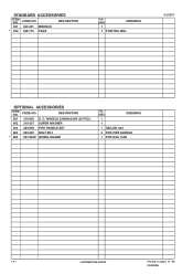
... change without any obligation on the part of the HITACHI. 17 STANDARD ACCESSORIES ⅜ Wrench (Code No. 937913Z 1 ⅜ Side Handle (Code No. 322411 1 OPTIONAL ACCESSORIES ..... sold separately ⅜ Depressed center wheel (10pcs. English ACCESSORIES WARNING: Never use any accessories other than those mentioned below or attachments not intended for use of any accessories other than those mentionded below . The use such as cup wheel, cut-off wheel or saw blade...
... change without any obligation on the part of the HITACHI. 17 STANDARD ACCESSORIES ⅜ Wrench (Code No. 937913Z 1 ⅜ Side Handle (Code No. 322411 1 OPTIONAL ACCESSORIES ..... sold separately ⅜ Depressed center wheel (10pcs. English ACCESSORIES WARNING: Never use any accessories other than those mentioned below or attachments not intended for use of any accessories other than those mentionded below . The use such as cup wheel, cut-off wheel or saw blade...
Instruction Manual
Page 49
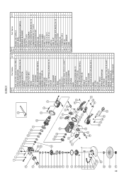
... TAPPING SCREW (W/FLANGE) D4×16 54 CARBON BRUSH 7×17×22.5 55 BRUSH HOLDER SET 56 HANDLE (B) 57 BRUSH COVER 58 HITACHI LABEL 59 NAME PLATE 60 O-RING (I.D. 24.7) 61 O-RING (I.D. 31.2) 62 SWITCH 63 CORD CLIP 64 TAPPING SCREW (W/FLANGE) D4×16 65 SWITCH COVER 66 HANDLE (A) 67 TERMINAL M4.0 68 TUBE (D) 69 CORD ARMOR 70 CORD 501 WRENCH Q'TY 1 1 1 1 1 1 1 8 2 2 1 1 1 1 1 1 1 1 2 1 1 2 2 1 1 1 49 Part Name Q'TY 1 SEAL LOCK...
... TAPPING SCREW (W/FLANGE) D4×16 54 CARBON BRUSH 7×17×22.5 55 BRUSH HOLDER SET 56 HANDLE (B) 57 BRUSH COVER 58 HITACHI LABEL 59 NAME PLATE 60 O-RING (I.D. 24.7) 61 O-RING (I.D. 31.2) 62 SWITCH 63 CORD CLIP 64 TAPPING SCREW (W/FLANGE) D4×16 65 SWITCH COVER 66 HANDLE (A) 67 TERMINAL M4.0 68 TUBE (D) 69 CORD ARMOR 70 CORD 501 WRENCH Q'TY 1 1 1 1 1 1 1 8 2 2 1 1 1 1 1 1 1 1 2 1 1 2 2 1 1 1 49 Part Name Q'TY 1 SEAL LOCK...
Instruction Manual
Page 50
... 65 SWITCH COVER 66 HANDLE (A) 67 TERMINAL M4.0 68 TUBE (D) 69 CORD ARMOR 70 CORD 501 WRENCH Q'TY 1 1 1 1 1 1 1 8 2 2 1 1 1 1 1 1 1 1 2 1 1 2 2 1 1 1 SOCKET HD. C. WHEELS 230MM A24R 1 Item No. HD. 50 G23SCY Item No. BOLT (W/FLANGE) M5×16 4 36 LABEL 1 37 SET PIN 1 38 LEVER 1 39 BOLT M8×22 1 40 SPRING WASHER M8 1 41 SET PIECE 1 42 RETAINING RING (E-TYPE) FOR D5 SHAFT 1 43 WHEEL GUARD ASS'Y 1 44 WHEEL WASHER (A) 1 45 D. Part...
... 65 SWITCH COVER 66 HANDLE (A) 67 TERMINAL M4.0 68 TUBE (D) 69 CORD ARMOR 70 CORD 501 WRENCH Q'TY 1 1 1 1 1 1 1 8 2 2 1 1 1 1 1 1 1 1 2 1 1 2 2 1 1 1 SOCKET HD. C. WHEELS 230MM A24R 1 Item No. HD. 50 G23SCY Item No. BOLT (W/FLANGE) M5×16 4 36 LABEL 1 37 SET PIN 1 38 LEVER 1 39 BOLT M8×22 1 40 SPRING WASHER M8 1 41 SET PIECE 1 42 RETAINING RING (E-TYPE) FOR D5 SHAFT 1 43 WHEEL GUARD ASS'Y 1 44 WHEEL WASHER (A) 1 45 D. Part...
Parts List
Page 2
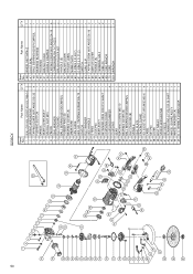
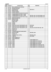
... 937-923P WHEEL NUT 5/8"-11UNC 1 FOR USA, CAN 44 320-216 DUST SEAL 1 --- 2 --- * ALTERNATIVE PARTS G 23SCY 9 -- 06 CODE NO. 1 984-509 DESCRIPTION NO. USED SEAL LOCK HEX. BOLT M5X14 2 REMARKS 2 323-209 TAPPING SCREW (W/FLANGE) D5X35 (BLACK) 4 3 306-888 PUSHING BUTTON 1 4 320-219 SPRING 1 5 326-717 GEAR COVER ASS'Y 1 INCLUD. 3, 4, 16, 18, 19 6 320-226 SPECIAL NUT M10 1 7 320-221 SEAL WASHER 1 8 320...
... 937-923P WHEEL NUT 5/8"-11UNC 1 FOR USA, CAN 44 320-216 DUST SEAL 1 --- 2 --- * ALTERNATIVE PARTS G 23SCY 9 -- 06 CODE NO. 1 984-509 DESCRIPTION NO. USED SEAL LOCK HEX. BOLT M5X14 2 REMARKS 2 323-209 TAPPING SCREW (W/FLANGE) D5X35 (BLACK) 4 3 306-888 PUSHING BUTTON 1 4 320-219 SPRING 1 5 326-717 GEAR COVER ASS'Y 1 INCLUD. 3, 4, 16, 18, 19 6 320-226 SPECIAL NUT M10 1 7 320-221 SEAL WASHER 1 8 320...
Parts List
Page 3
...-323 BRUSH HOLDER SET 2 53 326-715 BRUSH COVER 1 54 HITACHI LABEL 1 55 NAME PLATE 1 56 326-724 O-RING 1 57 326-725 O-RING 1 * 58 320-238 SWITCH (2P PILLAR TYPE) W/SAFETY LOCK 1 OFF/LOCK * 58 320-239 SWITCH (2P PILLAR TYPE) W/SAFETY LOCK 1 W/LOCK * 58 322-614 SWITCH (2P PILLAR TYPE) W/SAFETY LOCK 1 INCLUD. 62 W/LOCK FOR USA, CAN 59 326-714 HANDLE (B) 1 60 960-266 CORD CLIP 1 61 984-750 TAPPING SCREW (W/FLANGE...
...-323 BRUSH HOLDER SET 2 53 326-715 BRUSH COVER 1 54 HITACHI LABEL 1 55 NAME PLATE 1 56 326-724 O-RING 1 57 326-725 O-RING 1 * 58 320-238 SWITCH (2P PILLAR TYPE) W/SAFETY LOCK 1 OFF/LOCK * 58 320-239 SWITCH (2P PILLAR TYPE) W/SAFETY LOCK 1 W/LOCK * 58 322-614 SWITCH (2P PILLAR TYPE) W/SAFETY LOCK 1 INCLUD. 62 W/LOCK FOR USA, CAN 59 326-714 HANDLE (B) 1 60 960-266 CORD CLIP 1 61 984-750 TAPPING SCREW (W/FLANGE...
Parts List
Page 4
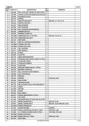
USED 1 REMARKS 1 FOR FRA, BEL G 23SCY OPTIONAL ACCESSORIES ITEM NO. C. USED REMARKS 1 1 1 INCLUD. 604 2 FOR PIPE HANDLE 1 FOR USA, CAN --- 4 --- * ALTERNATIVE PARTS Printed in Japan 9 -- 06 (060928N) CODE NO. STANDARD ACCESSORIES ITEM NO. CODE NO. WHEELS 230MM A24R (25 PCS.) 602 310-337 SUPER WASHER 603 323-993 PIPE HANDLE SET 604 985-597 BOLT M14 * 605 937-984Z WHEEL GUARD NO. DESCRIPTION 501 325-491 WRENCH * 502 326-175 CASE NO. DESCRIPTION 601 316-825 D.
USED 1 REMARKS 1 FOR FRA, BEL G 23SCY OPTIONAL ACCESSORIES ITEM NO. C. USED REMARKS 1 1 1 INCLUD. 604 2 FOR PIPE HANDLE 1 FOR USA, CAN --- 4 --- * ALTERNATIVE PARTS Printed in Japan 9 -- 06 (060928N) CODE NO. STANDARD ACCESSORIES ITEM NO. CODE NO. WHEELS 230MM A24R (25 PCS.) 602 310-337 SUPER WASHER 603 323-993 PIPE HANDLE SET 604 985-597 BOLT M14 * 605 937-984Z WHEEL GUARD NO. DESCRIPTION 501 325-491 WRENCH * 502 326-175 CASE NO. DESCRIPTION 601 316-825 D.

