
Instruction Manual
Page 3
... Read and understand all of this Instruction Manual and in the sections which contain the operation and maintenance instructions. Basic safety precautions are outlined in the "SAFETY" section of the safety precautions, warnings and operating instructions in the Instruction Manual before it occurs, and by HITACHI. NEVER use this power tool in minor or moderate injury, or may cause machine damage. NOTE emphasizes essential information. 3 MEANINGS...
... Read and understand all of this Instruction Manual and in the sections which contain the operation and maintenance instructions. Basic safety precautions are outlined in the "SAFETY" section of the safety precautions, warnings and operating instructions in the Instruction Manual before it occurs, and by HITACHI. NEVER use this power tool in minor or moderate injury, or may cause machine damage. NOTE emphasizes essential information. 3 MEANINGS...

Instruction Manual
Page 4
... if your mains-operated (corded) power tool or battery-operated (cordless) power tool. e) When operating a power tool outdoors, use an extension cord suitable for appropriate conditions will reduce personal injuries. Safety equipment such as dust mask, non-skid safety shoes, hard hat, or hearing protection used for outdoor use common sense when operating a power tool. c) Do not expose power tools to lose control. 2) Electrical Safety a) Power tool plugs must match the outlet. SAVE THESE INSTRUCTIONS 1) Work area safety a) Keep work area clean...
... if your mains-operated (corded) power tool or battery-operated (cordless) power tool. e) When operating a power tool outdoors, use an extension cord suitable for appropriate conditions will reduce personal injuries. Safety equipment such as dust mask, non-skid safety shoes, hard hat, or hearing protection used for outdoor use common sense when operating a power tool. c) Do not expose power tools to lose control. 2) Electrical Safety a) Power tool plugs must match the outlet. SAVE THESE INSTRUCTIONS 1) Work area safety a) Keep work area clean...

Instruction Manual
Page 5
... binding of starting . Use of the power tool is dangerous and must read instruction manual. 5 e) Maintain power tools. Many accidents are connected and properly used. Any power tool that the safety of these are caused by a qualified repair person using only identical replacement parts. g) Use the power tool, accessories and tool bits etc., in accordance with the switch is maintained. -WARNING- d) Remove any adjusting key or wrench before making any other condition that have the power tool repaired before use. Keep...
... binding of starting . Use of the power tool is dangerous and must read instruction manual. 5 e) Maintain power tools. Many accidents are connected and properly used. Any power tool that the safety of these are caused by a qualified repair person using only identical replacement parts. g) Use the power tool, accessories and tool bits etc., in accordance with the switch is maintained. -WARNING- d) Remove any adjusting key or wrench before making any other condition that have the power tool repaired before use. Keep...

Instruction Manual
Page 6
...'t use a power tool for applications other than those specified. Operate the tool according to a stable platform. If using it will make exposed metal parts of the tool "live " wire will result in the Instruction Manual. 8. Turn power off. If maintenance or servicing requires the removal of the tool. 6. Such tools should be kept clean so that air can freely flow at a higher voltage than those specified in abnormally fast motor...
...'t use a power tool for applications other than those specified. Operate the tool according to a stable platform. If using it will make exposed metal parts of the tool "live " wire will result in the Instruction Manual. 8. Turn power off. If maintenance or servicing requires the removal of the tool. 6. Such tools should be kept clean so that air can freely flow at a higher voltage than those specified in abnormally fast motor...

Instruction Manual
Page 7
... revision of this Instruction Manual, including not using the power tool in electric shock. Therefore, either the symbol " " or the words "Double insulation" appear on the power tool or on this tool V volts Hz hertz A amperes no no external grounding, you must still follow these precautions: ⅜ Only Hitachi Authorized Service Center should disassemble or assemble this system has no load speed W watt Class II...
... revision of this Instruction Manual, including not using the power tool in electric shock. Therefore, either the symbol " " or the words "Double insulation" appear on the power tool or on this tool V volts Hz hertz A amperes no no external grounding, you must still follow these precautions: ⅜ Only Hitachi Authorized Service Center should disassemble or assemble this system has no load speed W watt Class II...

Instruction Manual
Page 8
NEVER operate, or attempt any maintenance on your own power tool NAME OF PARTS Blade holder Front cover Lever Brush cap Switch trigger Blade Handle Base Base lever Push button Housing Rubber cap Change lever Dial SPECIFICATIONS Motor Power Source Current Capacity No-Load Speed Stroke Weight (without cord) 8 Fig. 1 Single-Phase, Series Commutator Motor Single-Phase, 120 V AC 60 Hz 13 A Mild Steel Pipe: O.D. 5" (130 mm) Vinyl Chloride Pipe: O.D. 5" (130 mm) Wood: Depth 5" (130 mm) 0 - 3000/min...
NEVER operate, or attempt any maintenance on your own power tool NAME OF PARTS Blade holder Front cover Lever Brush cap Switch trigger Blade Handle Base Base lever Push button Housing Rubber cap Change lever Dial SPECIFICATIONS Motor Power Source Current Capacity No-Load Speed Stroke Weight (without cord) 8 Fig. 1 Single-Phase, Series Commutator Motor Single-Phase, 120 V AC 60 Hz 13 A Mild Steel Pipe: O.D. 5" (130 mm) Vinyl Chloride Pipe: O.D. 5" (130 mm) Wood: Depth 5" (130 mm) 0 - 3000/min...

Instruction Manual
Page 9
... direction of a wrench or other tools. (1) Turn on and off and the power cord unplugged to be repaired. Thereafter, turn off the switch and unplug the power cord. (Fig. 2) Lever Front cover Fig. 2 CAUTION: Be absolutely sure to keep the switch turned off the switching trigger several times so that enables mounting and removal of saw blades without the use an extension cord of the front cover completely. English ASSEMBLY AND OPERATION APPLICATIONS ⅜ Cutting...
... direction of a wrench or other tools. (1) Turn on and off and the power cord unplugged to be repaired. Thereafter, turn off the switch and unplug the power cord. (Fig. 2) Lever Front cover Fig. 2 CAUTION: Be absolutely sure to keep the switch turned off the switching trigger several times so that enables mounting and removal of saw blades without the use an extension cord of the front cover completely. English ASSEMBLY AND OPERATION APPLICATIONS ⅜ Cutting...

Instruction Manual
Page 10
... pushed the lever in the direction of the front cover completely. Fig. 6 (5) Pull the back of the saw blade two or three times by hand and check that the lever can jump out of the arrow mark shown in Fig. 3, turn off the switch and unplug the power cord. (Fig. 2) CAUTION: Be absolutely sure to keep the switch turned off the switching trigger several...
... pushed the lever in the direction of the front cover completely. Fig. 6 (5) Pull the back of the saw blade two or three times by hand and check that the lever can jump out of the arrow mark shown in Fig. 3, turn off the switch and unplug the power cord. (Fig. 2) CAUTION: Be absolutely sure to keep the switch turned off the switching trigger several...

Instruction Manual
Page 11
... lever in Fig. 9, carry out lubrication around the blade holder on a periodic basis by use , blow away sawdust, earth, sand, moisture, etc., with air or brush them away with a brush, etc., to accumulated sawdust and chips. The rubber cap can function smoothly. (2) As shown in the direction of the arrow mark, and face the blade downward. Otherwise, the saw blade can adjust the base mounting...
... lever in Fig. 9, carry out lubrication around the blade holder on a periodic basis by use , blow away sawdust, earth, sand, moisture, etc., with air or brush them away with a brush, etc., to accumulated sawdust and chips. The rubber cap can function smoothly. (2) As shown in the direction of the arrow mark, and face the blade downward. Otherwise, the saw blade can adjust the base mounting...

Instruction Manual
Page 12
... a rough guide in selecting the suitable speed for adjustment (Fig. 12) Push button This unit has a built-in , the speed of a wrench or other tools. (1) Press a pushbutton. We recommend that makes it possible to adjust the variable speed of materials to ensure the accuracy of 1 - 2), never cut position. Example of the saw blade either both by pulling a switching trigger or turning a dial. (Fig. 15) Switch trigger Base lever Fig. 12 (2) Push...
... a rough guide in selecting the suitable speed for adjustment (Fig. 12) Push button This unit has a built-in , the speed of a wrench or other tools. (1) Press a pushbutton. We recommend that makes it possible to adjust the variable speed of materials to ensure the accuracy of 1 - 2), never cut position. Example of the saw blade either both by pulling a switching trigger or turning a dial. (Fig. 15) Switch trigger Base lever Fig. 12 (2) Push...

Instruction Manual
Page 13
... setting the change lever. Vibration can damage the saw with this unit employs a powerful motor, prolonged use at a low speed will increase the load unduly and may be damaged. Furthermore, a tip of the saw with your hand or finger beyond the flange (see Fig.18) of the machine through the plunger section during cutting operation. 10. HOW TO USE THE RECIPROCATING SAW CAUTION: ⅜ Avoid carrying it before use a saw blade...
... setting the change lever. Vibration can damage the saw with this unit employs a powerful motor, prolonged use at a low speed will increase the load unduly and may be damaged. Furthermore, a tip of the saw with your hand or finger beyond the flange (see Fig.18) of the machine through the plunger section during cutting operation. 10. HOW TO USE THE RECIPROCATING SAW CAUTION: ⅜ Avoid carrying it before use a saw blade...

Instruction Manual
Page 14
....22) Fig. 19 If you don't use proper machine oil (turbine oil, etc.). there is a risk that exceeds the cutting capacity of the saw blade when cutting. When not using and working conditions and materials. 14 Ideally, the length protruding from the base of the saw blade and the switching to suit your working conditions, adjust the speed of the saw blade after subtracting the stroke should be...
....22) Fig. 19 If you don't use proper machine oil (turbine oil, etc.). there is a risk that exceeds the cutting capacity of the saw blade when cutting. When not using and working conditions and materials. 14 Ideally, the length protruding from the base of the saw blade and the switching to suit your working conditions, adjust the speed of the saw blade after subtracting the stroke should be...
Instruction Manual
Page 15
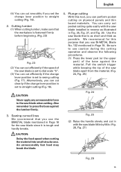
... breaks. Pull the switch trigger while keeping the tip of the saw blade installed in Page 18. CAUTION: Delay the feed speed when cutting the material into small circular arcs. An unreasonably fast feed may break the blade. 4. Be sure to use BI-METAL Blade No. 132 mentioned in reverse as possible. Alternatively, you can cut cleanly if the change lever position to straight...
... breaks. Pull the switch trigger while keeping the tip of the saw blade installed in Page 18. CAUTION: Delay the feed speed when cutting the material into small circular arcs. An unreasonably fast feed may break the blade. 4. Be sure to use BI-METAL Blade No. 132 mentioned in reverse as possible. Alternatively, you can cut cleanly if the change lever position to straight...

Instruction Manual
Page 16
... the material. ⅜ Make absolutely sure that you apply any unreasonable force to the saw blade during the cutting operation, the blade can easily damage the blade. ⅜ Never pull the switch trigger while the tip of the saw blade completely cuts into the material. (Fig. 28, Fig. 29) CAUTION: ⅜ Avoid plunge cutting for metallic materials. This can easily be damaged.
... the material. ⅜ Make absolutely sure that you apply any unreasonable force to the saw blade during the cutting operation, the blade can easily damage the blade. ⅜ Never pull the switch trigger while the tip of the saw blade completely cuts into the material. (Fig. 28, Fig. 29) CAUTION: ⅜ Avoid plunge cutting for metallic materials. This can easily be damaged.

Instruction Manual
Page 17
... replacement parts will eventually require servicing or replacement of parts because of the screws be easily removed. 6. At that they slide freely within the brush holders. Inspecting the blade Continued use . No. English MAINTENANCE AND INSPECTION WARNING: Be sure to the Hitachi Authorized Service Center when requesting repair or other maintenance. Inspecting the mounting screws Regularly inspect all service and repairs must be used, all mounting screws and ensure that time, replace both carbon brushes with a slotted-head screwdriver...
... replacement parts will eventually require servicing or replacement of parts because of the screws be easily removed. 6. At that they slide freely within the brush holders. Inspecting the blade Continued use . No. English MAINTENANCE AND INSPECTION WARNING: Be sure to the Hitachi Authorized Service Center when requesting repair or other maintenance. Inspecting the mounting screws Regularly inspect all service and repairs must be used, all mounting screws and ensure that time, replace both carbon brushes with a slotted-head screwdriver...

Instruction Manual
Page 18
NEVER use replacement parts or accessories which are not intended for use a particular replacement part or accessory with this tool. The use Only authorized HITACHI replacement parts and accessories. English ACCESSORIES WARNING: ALWAYS use of any obligation on the part of the HITACHI. Contact HITACHI if you are subject to use with your tool. STANDARD ACCESSORIES (1) Blade (Code No. 725362) ...1 (2) Case (Code No. 321142) ...1 18 NOTE: Accessories are not sure whether it is safe to change without any other...
NEVER use replacement parts or accessories which are not intended for use a particular replacement part or accessory with this tool. The use Only authorized HITACHI replacement parts and accessories. English ACCESSORIES WARNING: ALWAYS use of any obligation on the part of the HITACHI. Contact HITACHI if you are subject to use with your tool. STANDARD ACCESSORIES (1) Blade (Code No. 725362) ...1 (2) Case (Code No. 321142) ...1 18 NOTE: Accessories are not sure whether it is safe to change without any other...
Instruction Manual
Page 56
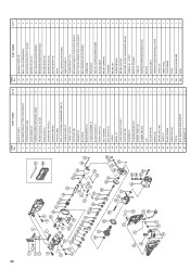
... 57 ARMATURE 58 FAN GUIDE 59 HEX. PART NAME 1 BASE (C) ASS'Y 2 RETAINING RING (E-TYPE) FOR D3 SHAFT 3 TAPPING SCREW D4X8 4 HOLD SPRING (C) 5 TAPPING SCREW (W/FLANGE) D4X25 6 FRONT COVER (D), (E) SET 7 BASE LEVER (C) 8 PUSHING BUTTON (C) 9 PUSHING SPRING 10 HITACHI LABEL 11 SEAL LOCK SCREW (W/WASHERS) M4X10 12 CHANGE KNOB (C) 13 O-RING (1AP-10) 14 LOCK NUT M8 15 WASHER (G) 16 BOLT M10 17 BASE ADAPTER (C) 18 CUSHION RUBBER (C) 19 BLADE HOLDER (C) 20 GEAR COVER (D) 21 FELT WASHER 22 SEAL SLEEVE...
... 57 ARMATURE 58 FAN GUIDE 59 HEX. PART NAME 1 BASE (C) ASS'Y 2 RETAINING RING (E-TYPE) FOR D3 SHAFT 3 TAPPING SCREW D4X8 4 HOLD SPRING (C) 5 TAPPING SCREW (W/FLANGE) D4X25 6 FRONT COVER (D), (E) SET 7 BASE LEVER (C) 8 PUSHING BUTTON (C) 9 PUSHING SPRING 10 HITACHI LABEL 11 SEAL LOCK SCREW (W/WASHERS) M4X10 12 CHANGE KNOB (C) 13 O-RING (1AP-10) 14 LOCK NUT M8 15 WASHER (G) 16 BOLT M10 17 BASE ADAPTER (C) 18 CUSHION RUBBER (C) 19 BLADE HOLDER (C) 20 GEAR COVER (D) 21 FELT WASHER 22 SEAL SLEEVE...

Parts List
Page 1
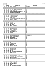
E713 ELECTRIC TOOL PARTS LIST RECIPROCATING SAW Model CR 13VBY 2007 • 2 • 5 (E1) 1 2 3 4 5 10 12 11 6 501 9 502 7 8 19 14 15 13 16 39 17 40 18 41 42 43 44 45 46 56 57 58 73 20 21 22 23 24 25 33 32 31 26 27 28 29 30 47 46 45 36 35 34 48 43 49 38 37 59 50 51 54 13 53 52 60 61 55 51 72 67 71 78 70 69 68 79 80 74 77 76 75 62 63 64 65 66 Hitachi Power Tools LIST NO.
E713 ELECTRIC TOOL PARTS LIST RECIPROCATING SAW Model CR 13VBY 2007 • 2 • 5 (E1) 1 2 3 4 5 10 12 11 6 501 9 502 7 8 19 14 15 13 16 39 17 40 18 41 42 43 44 45 46 56 57 58 73 20 21 22 23 24 25 33 32 31 26 27 28 29 30 47 46 45 36 35 34 48 43 49 38 37 59 50 51 54 13 53 52 60 61 55 51 72 67 71 78 70 69 68 79 80 74 77 76 75 62 63 64 65 66 Hitachi Power Tools LIST NO.
Parts List
Page 2
... (D).(E) SET 1 7 326-597 BASE LEVER (C) 1 8 326-596 PUSHING BUTTON (C) 1 9 326-594 PUSHING SPRING 1 10 NAME PLATE 1 11 303-851 SEAL LOCK SCREW (W/WASHERS) M4X10 (BLACK) 1 12 326-593 CHANGE KNOB (C) 1 13 872-654 O-RING (1AP-10) 2 14 327-325 NUT M8 1 15 327-114 WASHER (G) 1 16 318-493 BOLT M10 2 17 326-574 BASE ADAPTER (C) 1 18 326-779 CUSHION RUBBER (C) 1 19 326-589 BLADE HOLDER (C) 1 20 327-116 GEAR...
... (D).(E) SET 1 7 326-597 BASE LEVER (C) 1 8 326-596 PUSHING BUTTON (C) 1 9 326-594 PUSHING SPRING 1 10 NAME PLATE 1 11 303-851 SEAL LOCK SCREW (W/WASHERS) M4X10 (BLACK) 1 12 326-593 CHANGE KNOB (C) 1 13 872-654 O-RING (1AP-10) 2 14 327-325 NUT M8 1 15 327-114 WASHER (G) 1 16 318-493 BOLT M10 2 17 326-574 BASE ADAPTER (C) 1 18 326-779 CUSHION RUBBER (C) 1 19 326-589 BLADE HOLDER (C) 1 20 327-116 GEAR...

Parts List
Page 3
... STATOR ASS'Y 240V 1 INCLUD. 61 61 930-703 BRUSH TERMINAL 2 62 327-126 HOUSING 1 63 945-161 BRUSH CAP 2 64 999-043 CARBON BRUSH (1 PAIR) 2 65 958-900 BRUSH HOLDER 2 66 307-224 MACHINE SCREW (W/WASHERS) M5X60 (BLACK) 4 * 67 326-600 HANDLE (E).(F) SET 1 * 67 326-599 HANDLE (E).(F) SET 1 FOR AUS, NZL 68 322-133 SWITCH TRIGGER 1 * 69 981-373 TUBE (D) 1 FOR SIN, KUW, IND...
... STATOR ASS'Y 240V 1 INCLUD. 61 61 930-703 BRUSH TERMINAL 2 62 327-126 HOUSING 1 63 945-161 BRUSH CAP 2 64 999-043 CARBON BRUSH (1 PAIR) 2 65 958-900 BRUSH HOLDER 2 66 307-224 MACHINE SCREW (W/WASHERS) M5X60 (BLACK) 4 * 67 326-600 HANDLE (E).(F) SET 1 * 67 326-599 HANDLE (E).(F) SET 1 FOR AUS, NZL 68 322-133 SWITCH TRIGGER 1 * 69 981-373 TUBE (D) 1 FOR SIN, KUW, IND...


