
Owners Guide
Page 5
...use caution when moving ) patterns can cause permanent damage to the monitor. Do not place any objects on this product may require specific instructions pertaining to your safety. If an outside antenna is connected to the receiver be connected to the grounding system of the ... cart/apparatus combination to Article 820-40 of the obsolete outlet. 10. For disposal or recycling information, please contact your HITACHI Factory Warranty. ENGLISH IMPORTANT SAFETY INSTRUCTIONS Read before operating equipment Follow all warnings and instructions marked on the top of the monitor...
...use caution when moving ) patterns can cause permanent damage to the monitor. Do not place any objects on this product may require specific instructions pertaining to your safety. If an outside antenna is connected to the receiver be connected to the grounding system of the ... cart/apparatus combination to Article 820-40 of the obsolete outlet. 10. For disposal or recycling information, please contact your HITACHI Factory Warranty. ENGLISH IMPORTANT SAFETY INSTRUCTIONS Read before operating equipment Follow all warnings and instructions marked on the top of the monitor...

Owners Guide
Page 7
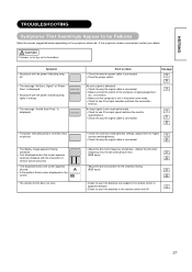
...OF PLASMA DISPLAY ......26 NOTES 26 TROUBLESHOOTING 27 Symptoms That Seemingly Appear to be Failures 27 Actions to Correct Abnormal Displays 29 PRODUCT SPECIFICATIONS 30 Signal Input 30 Recommended Signal List 31 SUPPLEMENT 33 Optional Video Unit Function 34 Notes about This Manual • The information ...in this manual is subject to using the product, such as hardware and software specifications and constraints, in this manual, you are requested to notify your dealer or us should you have any comments, views or questions ...
...OF PLASMA DISPLAY ......26 NOTES 26 TROUBLESHOOTING 27 Symptoms That Seemingly Appear to be Failures 27 Actions to Correct Abnormal Displays 29 PRODUCT SPECIFICATIONS 30 Signal Input 30 Recommended Signal List 31 SUPPLEMENT 33 Optional Video Unit Function 34 Notes about This Manual • The information ...in this manual is subject to using the product, such as hardware and software specifications and constraints, in this manual, you are requested to notify your dealer or us should you have any comments, views or questions ...
Owners Guide
Page 11
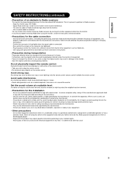
... coaxial cable for unattended operation or has a stand-by mode. Also confirm the screws on when it is unattended unless it is specifically stated that it is better to do this monitor influences Radio receivers by the manufacturer, or sold with wood screws - Failure to transport... the monitor in any carton except the original carton may require specific instructions pertaining to overturn resulting in damage to the instructions. - Do not physically impact the remote control. Avoid strong rays. Any strong...
... coaxial cable for unattended operation or has a stand-by mode. Also confirm the screws on when it is unattended unless it is specifically stated that it is better to do this monitor influences Radio receivers by the manufacturer, or sold with wood screws - Failure to transport... the monitor in any carton except the original carton may require specific instructions pertaining to overturn resulting in damage to the instructions. - Do not physically impact the remote control. Avoid strong rays. Any strong...
Owners Guide
Page 16
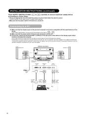
Connecting to a PC (1) Make sure that the display signal of the personal computer to be used is compatible with the specifications of this device. • See "Product Specifications" concerning the specifications of this device and the output terminal of the personal computer. • Depending on the rear panel of this device to the display...
Connecting to a PC (1) Make sure that the display signal of the personal computer to be used is compatible with the specifications of this device. • See "Product Specifications" concerning the specifications of this device and the output terminal of the personal computer. • Depending on the rear panel of this device to the display...
Owners Guide
Page 27
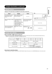
... When Mode Display is pressed. Signal, and Power Save (for the input terminal and the horizontal and vertical sync frequency. Recheck the input signal specifications. Signal ! Min RGB2 RGB H : 48.4kHz V : 60.1 Hz ! No Sync. ENGLISH OTHER FEATURES (continued) Signal Check Changes in... No Sync. Action When the sync signal is selected • When this unit. When the input signal does not match the monitor specifications or is displayed for approx. 5 sec.) • When the condition continues where the sync signal cannot be activated automatically when the computer...
... When Mode Display is pressed. Signal, and Power Save (for the input terminal and the horizontal and vertical sync frequency. Recheck the input signal specifications. Signal ! Min RGB2 RGB H : 48.4kHz V : 60.1 Hz ! No Sync. ENGLISH OTHER FEATURES (continued) Signal Check Changes in... No Sync. Action When the sync signal is selected • When this unit. When the input signal does not match the monitor specifications or is displayed for approx. 5 sec.) • When the condition continues where the sync signal cannot be activated automatically when the computer...
Owners Guide
Page 29
... • No picture with the power indicating lamp lights in the power-save mode. • Check to see if the input signal matches the monitor specifications. • Check the way the signal cable is connected. • The power indicating lamp is normally lit but no picture . • The display image appears...
... • No picture with the power indicating lamp lights in the power-save mode. • Check to see if the input signal matches the monitor specifications. • Check the way the signal cable is connected. • The power indicating lamp is normally lit but no picture . • The display image appears...

Owners Guide
Page 32
PRODUCT SPECIFICATIONS Product specifications and designs are subject to 90% (non-condensing) Power supply AC100 - 240V, 50/60Hz Power consumption/at standby 310W / Panel Display dimensions Resolution Approx. 42 ...
PRODUCT SPECIFICATIONS Product specifications and designs are subject to 90% (non-condensing) Power supply AC100 - 240V, 50/60Hz Power consumption/at standby 310W / Panel Display dimensions Resolution Approx. 42 ...
Owners Guide
Page 33
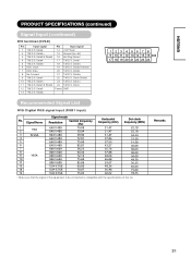
...Signal List With Digital RGB signal input (RGB1 input) • Make sure that the signal of the equipment to be connected is compatible with the specifications of this list. Clock+ 11 T.M.D.S. Frame GND 13 T.M.D.S. Clock- 12 T.M.D.S. Data2/4 Shield 16 Hot Plug Detect 4 T.M.D.S. Data0+ 6 DDC...Data4+ 18 T.M.D.S. Data1/3 Shield 24 T.M.D.S. Data2+ 15 Ground (for+5V) 3 T.M.D.S. Data5- 8 No Connect 21 T.M.D.S. Data1+ 23 T.M.D.S. ENGLISH PRODUCT SPECIFICATIONS (continued) Signal Input (continued) DVI terminal (DVI-D) Pin Input signal Pin Input signal 1 T.M.D.S.
...Signal List With Digital RGB signal input (RGB1 input) • Make sure that the signal of the equipment to be connected is compatible with the specifications of this list. Clock+ 11 T.M.D.S. Frame GND 13 T.M.D.S. Clock- 12 T.M.D.S. Data2/4 Shield 16 Hot Plug Detect 4 T.M.D.S. Data0+ 6 DDC...Data4+ 18 T.M.D.S. Data1/3 Shield 24 T.M.D.S. Data2+ 15 Ground (for+5V) 3 T.M.D.S. Data5- 8 No Connect 21 T.M.D.S. Data1+ 23 T.M.D.S. ENGLISH PRODUCT SPECIFICATIONS (continued) Signal Input (continued) DVI terminal (DVI-D) Pin Input signal Pin Input signal 1 T.M.D.S.
Owners Guide
Page 34
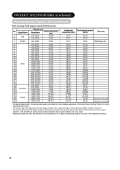
PRODUCT SPECIFICATIONS (continued) Recommended Signal List (continued) With Analog RGB signal input (RGB2 input) • The type of video board or connecting cable used may not allow ...
PRODUCT SPECIFICATIONS (continued) Recommended Signal List (continued) With Analog RGB signal input (RGB2 input) • The type of video board or connecting cable used may not allow ...
Owners Guide
Page 36
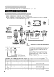
... the imaging device is turned off. (3) Use a commercially available cable and connector to receive RGB signal. Applicable video signals for each input terminal (See PRODUCT SPECIFICATIONS for the terminal form of video equipment. • If video equipment with an S video output terminal is used, cabling by the S video cable is recommended...
... the imaging device is turned off. (3) Use a commercially available cable and connector to receive RGB signal. Applicable video signals for each input terminal (See PRODUCT SPECIFICATIONS for the terminal form of video equipment. • If video equipment with an S video output terminal is used, cabling by the S video cable is recommended...

Owners Guide
Page 45
When it does occur, change to 90% (non-condensing) Power supply AC100 - 240V, 50/60Hz Power consumption/at standby 310W / This is connected. PRODUCT SPECIFICATIONS This table shows the specifications when the optional video unit has been inserted. occur. Panel Display dimensions Resolution Approx. 42 inches (920 (H) x 518 (V) mm, diagonal 1059mm) 852 (H) x 480...
When it does occur, change to 90% (non-condensing) Power supply AC100 - 240V, 50/60Hz Power consumption/at standby 310W / This is connected. PRODUCT SPECIFICATIONS This table shows the specifications when the optional video unit has been inserted. occur. Panel Display dimensions Resolution Approx. 42 inches (920 (H) x 518 (V) mm, diagonal 1059mm) 852 (H) x 480...
Owners Guide
Page 46
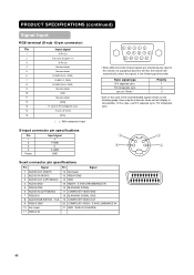
... following page, there may be instances when correct display is not possible. S-input connector pin specifications Pin 1 2 3 4 Frame Input signal Y Y-GND C C-GND GND ᶅ ᶃ ᶆ ᶄ Scart connector pin specifications Pin Signal 1 AUDIO OUT (RIGHT) 2 AUDIO IN (RIGHT) 3 AUDIO OUT (LEFT/MONO...No connection R.GND (PR/CR, GND) G.GND (Y, GND) B.GND (PB/CB, GND) No connection GND No connection [SDA] H. H/V composite sync. PRODUCT SPECIFICATIONS (continued) Signal Input RGB terminal (D-sub 15-pin connector) Pin 1 2 3 4 5 6 7 8 9 10 11 12 13 14 15 Input signal R ...
... following page, there may be instances when correct display is not possible. S-input connector pin specifications Pin 1 2 3 4 Frame Input signal Y Y-GND C C-GND GND ᶅ ᶃ ᶆ ᶄ Scart connector pin specifications Pin Signal 1 AUDIO OUT (RIGHT) 2 AUDIO IN (RIGHT) 3 AUDIO OUT (LEFT/MONO...No connection R.GND (PR/CR, GND) G.GND (Y, GND) B.GND (PB/CB, GND) No connection GND No connection [SDA] H. H/V composite sync. PRODUCT SPECIFICATIONS (continued) Signal Input RGB terminal (D-sub 15-pin connector) Pin 1 2 3 4 5 6 7 8 9 10 11 12 13 14 15 Input signal R ...
Owners Guide
Page 47
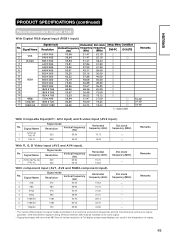
... 59.94 625 50.00 Horizontal frequency (kHz) 15.73 15.63 Dot clock frequency (MHz) Remarks With R, G, B Video input (AV2 and AV4 input). PRODUCT SPECIFICATIONS (continued) Recommended Signal List With Digital RGB signal input (RGB1 input) ENGLISH ( With Composite Input(AV1~AV4 input) and S-video Input (AV3 input). No. No.
... 59.94 625 50.00 Horizontal frequency (kHz) 15.73 15.63 Dot clock frequency (MHz) Remarks With R, G, B Video input (AV2 and AV4 input). PRODUCT SPECIFICATIONS (continued) Recommended Signal List With Digital RGB signal input (RGB1 input) ENGLISH ( With Composite Input(AV1~AV4 input) and S-video Input (AV3 input). No. No.