Instruction Manual
Page 3
... has not been specifically recommended by observing appropriate safety procedures. All visitors should be avoided by recognizing a potentially hazardous situation before it occurs, and by HITACHI. MAKE WORKSHOP CHILD PROOF with steel toes. An accident can often be kept safe distance from power tool operation and maintenance are caused by not...
... has not been specifically recommended by observing appropriate safety procedures. All visitors should be avoided by recognizing a potentially hazardous situation before it occurs, and by HITACHI. MAKE WORKSHOP CHILD PROOF with steel toes. An accident can often be kept safe distance from power tool operation and maintenance are caused by not...
Instruction Manual
Page 4
...or a vise to use a face mask for changing accessories. 14. NEVER OVERREACH. ALWAYS MAINTAIN TOOLS WITH CARE. Always follow instructions for lubricating the tool and for additional safety, and wear a dust mask if the cutting operation produces dust. 11. ALWAYS CHECK FOR DAMAGED PARTS BEFORE ...electrician to a complete stop . 21. Prevent serious injury by not tipping the tool and by not risking unintentional contact with the saw blade or other conditions that the switch is not in conjunction with the safety rules and operating instructions for this tool. 17....
...or a vise to use a face mask for changing accessories. 14. NEVER OVERREACH. ALWAYS MAINTAIN TOOLS WITH CARE. Always follow instructions for lubricating the tool and for additional safety, and wear a dust mask if the cutting operation produces dust. 11. ALWAYS CHECK FOR DAMAGED PARTS BEFORE ...electrician to a complete stop . 21. Prevent serious injury by not tipping the tool and by not risking unintentional contact with the saw blade or other conditions that the switch is not in conjunction with the safety rules and operating instructions for this tool. 17....
Instruction Manual
Page 5
...pressure as the sides of the saw blade with a vise assembly. 24. Always operate the tool after ensuring the workpiece is correct for use on , gently lower the blade to completely stop before switch is free from your machine be lulled into a false sense of dry cut . 22. Always turn off... thrown from power supply outlet. otherwise the workpiece might be alert at all times, especially during start-up and stopping. 29. Always handle the saw . 14. Don't be missing, damaged or fail in the proper places, before using the tool. 18. If you are fully open before using the ...
...pressure as the sides of the saw blade with a vise assembly. 24. Always operate the tool after ensuring the workpiece is correct for use on , gently lower the blade to completely stop before switch is free from your machine be lulled into a false sense of dry cut . 22. Always turn off... thrown from power supply outlet. otherwise the workpiece might be alert at all times, especially during start-up and stopping. 29. Always handle the saw . 14. Don't be missing, damaged or fail in the proper places, before using the tool. 18. If you are fully open before using the ...
Instruction Manual
Page 6
... to rain or use . 8. Never use length stops against it while the blade is 14" (355mm). 8. WARNING FOR YOUR OWN SAFETY READ THIS INSTRUCTION MANUAL BEFORE OPERATING THE DRY CUT METAL SAW 1. Never reach around the saw blade. 3. Never remove any freehand operation with solvents because the plastic may dissolve. 16. Never expose hands, feet...
... to rain or use . 8. Never use length stops against it while the blade is 14" (355mm). 8. WARNING FOR YOUR OWN SAFETY READ THIS INSTRUCTION MANUAL BEFORE OPERATING THE DRY CUT METAL SAW 1. Never reach around the saw blade. 3. Never remove any freehand operation with solvents because the plastic may dissolve. 16. Never expose hands, feet...
Instruction Manual
Page 7
Repairs should be conducted only by a Hitachi authorized service center. WARNING: Avoid electrical shock hazard. SAVE THESE INSTRUCTIONS AND MAKE THEM AVAILABLE TO OTHER USERS AND OWNERS OF THIS TOOL! 7 Never use this tool with a damaged or frayed electrical cord or extension cord. Inspect all electrical cords regularly. Never use in or near water or in any environment where electric shock is possible. English REPLACEMENT PARTS When servicing use only identical replacement parts.
Repairs should be conducted only by a Hitachi authorized service center. WARNING: Avoid electrical shock hazard. SAVE THESE INSTRUCTIONS AND MAKE THEM AVAILABLE TO OTHER USERS AND OWNERS OF THIS TOOL! 7 Never use this tool with a damaged or frayed electrical cord or extension cord. Inspect all electrical cords regularly. Never use in or near water or in any environment where electric shock is possible. English REPLACEMENT PARTS When servicing use only identical replacement parts.
Instruction Manual
Page 8
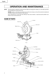
NEVER operate, or attempt any maintenance on your own power tool NAME OF PARTS Sub Cover Handle Safety Cover Saw Cover Shaft Side Cover Motor Tail Cover Spring (B) Hinge Vise (B) Base Fig. 1 Fig. 2 Eye Shield Trigger Switch Hook Vise (A) Screw Quick Lock Vise Screw Handle ...
NEVER operate, or attempt any maintenance on your own power tool NAME OF PARTS Sub Cover Handle Safety Cover Saw Cover Shaft Side Cover Motor Tail Cover Spring (B) Hinge Vise (B) Base Fig. 1 Fig. 2 Eye Shield Trigger Switch Hook Vise (A) Screw Quick Lock Vise Screw Handle ...
Instruction Manual
Page 9
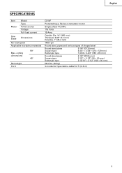
cutting dimensions 45° Net weight Cord CD14F Protected type, Series commutator motor Single-phase AC 60Hz 115 Volts 15 Amp Outside Dia. 14" (355 mm) Thickness 3/32" (2.4 mm) Hole Dia. 1" (25.4 mm) 1490 rpm Round steel, pipes and various types of shaped steel Round steel pipes Square type ...; 3-1/2" (100 × 90 mm) 52.9 lbs. (24 kg) 3 conductor type cabtire cable 8.2 ft (2.5 m) 9 English SPECIFICATIONS Item Motor Model Type Power source Voltage Full-load current Saw blade Dimensions No-load speed Applicable workpiece materials 90° Max.
cutting dimensions 45° Net weight Cord CD14F Protected type, Series commutator motor Single-phase AC 60Hz 115 Volts 15 Amp Outside Dia. 14" (355 mm) Thickness 3/32" (2.4 mm) Hole Dia. 1" (25.4 mm) 1490 rpm Round steel, pipes and various types of shaped steel Round steel pipes Square type ...; 3-1/2" (100 × 90 mm) 52.9 lbs. (24 kg) 3 conductor type cabtire cable 8.2 ft (2.5 m) 9 English SPECIFICATIONS Item Motor Model Type Power source Voltage Full-load current Saw blade Dimensions No-load speed Applicable workpiece materials 90° Max.
Instruction Manual
Page 10
... Tool's Plug Grounding Methods Grounding Pin (A) Adapter Cover of electric shock. If repair or replacement of the electric cord or plug is necessary, do not cut except for use on . Check with an receptacle similar to a live terminal. Use only 3-core extension cords that have 3-prong grounding plugs and 3-pole receptacles...
... Tool's Plug Grounding Methods Grounding Pin (A) Adapter Cover of electric shock. If repair or replacement of the electric cord or plug is necessary, do not cut except for use on . Check with an receptacle similar to a live terminal. Use only 3-core extension cords that have 3-prong grounding plugs and 3-pole receptacles...
Instruction Manual
Page 11
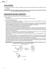
cord length Wire gauge size A.W.G (mm2) 25 ft (7.5 m) 14 A.W.G (2.0 mm2) 50 ft. (15 m) 12 A.W.G (3.5 mm2) 100 ft. (30.5 m) Not recommended To use the power tool when no suitable power source is designed to secure the saw blade. Check power cord and extension cords for the tool. Make ...sure the trigger switch is connected to an electrical power source until all operating instructions have been read and understood. 4. Confirm that the saw blade is fixed securely to 16.0 Ext. English 3. Determine from the handle. Repair or replace as that accept the tool's plug. Confirm...
cord length Wire gauge size A.W.G (mm2) 25 ft (7.5 m) 14 A.W.G (2.0 mm2) 50 ft. (15 m) 12 A.W.G (3.5 mm2) 100 ft. (30.5 m) Not recommended To use the power tool when no suitable power source is designed to secure the saw blade. Check power cord and extension cords for the tool. Make ...sure the trigger switch is connected to an electrical power source until all operating instructions have been read and understood. 4. Confirm that the saw blade is fixed securely to 16.0 Ext. English 3. Determine from the handle. Repair or replace as that accept the tool's plug. Confirm...
Instruction Manual
Page 12
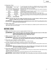
... 9. AFTER CONNECTING THE POWER PLUG TO AN APPROPRIATE AC POWER SOURCE, CHECK THE OPERATION OF THE TOOL AS FOLLOWS: 11. For precise cutting, rotate the saw blade breaks during rotation. To operate the power tool, it is damaged. The trigger switch will deteriorate. 8. Check the Power Receptacle. ...Repair or replace the receptacle if it is not damaged. Check facial deflection by rotating the saw blade, confirm that the blade is not, a serious accident could be shortened and cutting precision will not operate unless the lock-off button into the hole on while pushing the spindle...
... 9. AFTER CONNECTING THE POWER PLUG TO AN APPROPRIATE AC POWER SOURCE, CHECK THE OPERATION OF THE TOOL AS FOLLOWS: 11. For precise cutting, rotate the saw blade breaks during rotation. To operate the power tool, it is damaged. The trigger switch will deteriorate. 8. Check the Power Receptacle. ...Repair or replace the receptacle if it is not damaged. Check facial deflection by rotating the saw blade, confirm that the blade is not, a serious accident could be shortened and cutting precision will not operate unless the lock-off button into the hole on while pushing the spindle...
Instruction Manual
Page 13
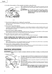
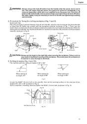
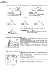
...) bolt, as shown in Fig. 9. This could cause the workpiece to be necessary to turn it may be ejected or cause damage to the blade. 3. Cutting at an angle of 45° Fig. 9 Loosen the 25/64" (10 mm) bolt on accidentally or by turning the Screw Handle. Upon completion of... removing. 2. Quick Lock Vise Place the workpiece material between Vise (A) and Vise (B), raise the clutch and push the Screw Handle to use . The machine permits cutting at angles of 45° or 60° When setting at an angle of 0° When setting at an angle of 30° When setting...
...) bolt, as shown in Fig. 9. This could cause the workpiece to be necessary to turn it may be ejected or cause damage to the blade. 3. Cutting at an angle of 45° Fig. 9 Loosen the 25/64" (10 mm) bolt on accidentally or by turning the Screw Handle. Upon completion of... removing. 2. Quick Lock Vise Place the workpiece material between Vise (A) and Vise (B), raise the clutch and push the Screw Handle to use . The machine permits cutting at angles of 45° or 60° When setting at an angle of 0° When setting at an angle of 30° When setting...
Instruction Manual
Page 14
...(2) Adjust that white line of vise (B) is suitable for white line of base. (3) Adjust that it is, the cutting material will move and cutting accuracy will deteriorate. Moving the stationary vise-jaw (Fig. 14) The vise opening can be set . (Fig. 11) Vise (B) Side Cover Vise (B) Side Cover Wing Bolt Fig.... 11 Wing Bolt Fig. 12 Cutting Material in 8-17/32" (217 mm). In case the vise (B) opening more than 7-5/16" (186 mm) is ...
...(2) Adjust that white line of vise (B) is suitable for white line of base. (3) Adjust that it is, the cutting material will move and cutting accuracy will deteriorate. Moving the stationary vise-jaw (Fig. 14) The vise opening can be set . (Fig. 11) Vise (B) Side Cover Vise (B) Side Cover Wing Bolt Fig.... 11 Wing Bolt Fig. 12 Cutting Material in 8-17/32" (217 mm). In case the vise (B) opening more than 7-5/16" (186 mm) is ...
Instruction Manual
Page 15
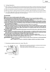
... vise. In this will wear down gradually to produce cutting. (3) When the cutting (or desired cutting-in more sparks and premature blade wear. ⅷ If the blade stops during cutting, immediately turn off and discarded is thin or narrow, if after the saw blade has completely stopped moving. ⅷ Ensure the... in ) has been completed, raise the handle up to its original position after cutting the handle is rotating at full speed, slowly push down the handle while holding down the lever and bring the saw blade and cause injury. Overload Switch FIg. 16 15 CAUTION: ⅷ Be ...
... vise. In this will wear down gradually to produce cutting. (3) When the cutting (or desired cutting-in more sparks and premature blade wear. ⅷ If the blade stops during cutting, immediately turn off and discarded is thin or narrow, if after the saw blade has completely stopped moving. ⅷ Ensure the... in ) has been completed, raise the handle up to its original position after cutting the handle is rotating at full speed, slowly push down the handle while holding down the lever and bring the saw blade and cause injury. Overload Switch FIg. 16 15 CAUTION: ⅷ Be ...
Instruction Manual
Page 16
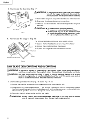
...CAUTION: Use only 17mm wrench provided to install removed wing bolt. How to use the stopper (Fig. 18) The stopper facilitates continuous same length cutting. (1) Loosen the hex head socket screw and pull the holder Stopper (2) Loosen the wing bolt and set the stopper (3) Tighten the wing bolt ... machine. (3) The dust box return into fix the saw blade maybe very hot. 16 it has been used for cutting several materials in ward. (3) Removing the bolt, wheel washer and the saw blade. WARNING: Be very carefull when removing the saw blade after it may result in the general vicinity of...
...CAUTION: Use only 17mm wrench provided to install removed wing bolt. How to use the stopper (Fig. 18) The stopper facilitates continuous same length cutting. (1) Loosen the hex head socket screw and pull the holder Stopper (2) Loosen the wing bolt and set the stopper (3) Tighten the wing bolt ... machine. (3) The dust box return into fix the saw blade maybe very hot. 16 it has been used for cutting several materials in ward. (3) Removing the bolt, wheel washer and the saw blade. WARNING: Be very carefull when removing the saw blade after it may result in the general vicinity of...
Instruction Manual
Page 17
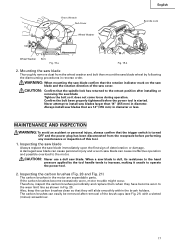
... is dull, its resistance to the retract position after removal of deterioration or damage. When a saw blades larger than 14" (355 mm) in diameter or less. Mounting the saw blade Thoroughly remove dust from the receptacle before the power tool is turned OFF and the power plug has been ...Tighten the bolt so it unsafe to the wear limit line as shown in the motor are 14" (355 mm) in diameter. Inspecting the saw blade Always replace the saw blade. WARNING: When mounting the saw blade confirm that the trigger switch is started. MAINTENANCE AND INSPECTION WARNING: To avoid an ...
... is dull, its resistance to the retract position after removal of deterioration or damage. When a saw blades larger than 14" (355 mm) in diameter or less. Mounting the saw blade Thoroughly remove dust from the receptacle before the power tool is turned OFF and the power plug has been ...Tighten the bolt so it unsafe to the wear limit line as shown in the motor are 14" (355 mm) in diameter. Inspecting the saw blade Always replace the saw blade. WARNING: When mounting the saw blade confirm that the trigger switch is started. MAINTENANCE AND INSPECTION WARNING: To avoid an ...
Instruction Manual
Page 18
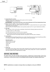
...position, (2) Power plug has been removed from contact with a damp, soapy cloth. To avoid a malfunction of the motor, protect it stored in a dry place out of the reach of machine oil is not in use the tool unless the safety covers operate properly and it is in good... covers (see Fig. 1 and Fig. 2). NOTE: Specifications are loose. 4. SERVICE AND REPAIRS All quality power tools will be performed by an AUTHORIZED HITACHI POWER TOOL REPAIR CENTER ONLY. When the tool is recommended. Cleaning Periodically remove chips, dust and other than routine maintenance) must be used, all service...
...position, (2) Power plug has been removed from contact with a damp, soapy cloth. To avoid a malfunction of the motor, protect it stored in a dry place out of the reach of machine oil is not in use the tool unless the safety covers operate properly and it is in good... covers (see Fig. 1 and Fig. 2). NOTE: Specifications are loose. 4. SERVICE AND REPAIRS All quality power tools will be performed by an AUTHORIZED HITACHI POWER TOOL REPAIR CENTER ONLY. When the tool is recommended. Cleaning Periodically remove chips, dust and other than routine maintenance) must be used, all service...