Owners Guide
Page 1
IMPORTANT SAFEGUARDS PROJECTION COLOR TV 61SBX01B 53SBX01B OPERATING GUIDE TABLE OF CONTENTS IMPORTANT SAFEGUARDS ...2 SAFETY TIPS ...4 PICTURE CAUTIONS...9 ACCESSORIES ...9 REMOTE CONTROL BATTERY INSTALLATION AND REPLACEMENT 11 HOW TO SET UP YOUR NEW HITACHI PROJECTION TV 11 HOOK-UP CABLES AND CONNECTORS ...13 FRONT PANEL CONTROLS...15 FRONT PANEL JACKS AND CONNECTIONS...16...BRAND ...55 ULTRATEC OSD...56 SET UP ...59 CUSTOM ...67 AUTO LINK ...76 VIDEO ...80 THEATER ...85 INFO ...94 CARE OF YOUR HITACHI PROJECTION TV AND YOUR 97 REMOTE CONTROL ...97 RECEPTION PROBLEMS...98 USEFUL INFO ...99 1
IMPORTANT SAFEGUARDS PROJECTION COLOR TV 61SBX01B 53SBX01B OPERATING GUIDE TABLE OF CONTENTS IMPORTANT SAFEGUARDS ...2 SAFETY TIPS ...4 PICTURE CAUTIONS...9 ACCESSORIES ...9 REMOTE CONTROL BATTERY INSTALLATION AND REPLACEMENT 11 HOW TO SET UP YOUR NEW HITACHI PROJECTION TV 11 HOOK-UP CABLES AND CONNECTORS ...13 FRONT PANEL CONTROLS...15 FRONT PANEL JACKS AND CONNECTIONS...16...BRAND ...55 ULTRATEC OSD...56 SET UP ...59 CUSTOM ...67 AUTO LINK ...76 VIDEO ...80 THEATER ...85 INFO ...94 CARE OF YOUR HITACHI PROJECTION TV AND YOUR 97 REMOTE CONTROL ...97 RECEPTION PROBLEMS...98 USEFUL INFO ...99 1
Owners Guide
Page 3
... as this can expose you to very high voltages and other hazards. CAUTION: Never remove the back cover of the FCC rules. NEVER CONNECT THE TV TO 50Hz, DIRECT CURRENT, OR ANYTHING OTHER THAN THE SPECIFIED VOLTAGE.
... as this can expose you to very high voltages and other hazards. CAUTION: Never remove the back cover of the FCC rules. NEVER CONNECT THE TV TO 50Hz, DIRECT CURRENT, OR ANYTHING OTHER THAN THE SPECIFIED VOLTAGE.
Owners Guide
Page 9
...have the following accessories before disposing of the packing material. 9 Public Viewing of Copyrighted Material Public viewing of programs broadcast by your HITACHI Factory Warranty. • When using Picture-in-Picture function, the sub-picture should not be left permanently in one corner of the... BURN" may require prior authorization from the broadcaster or owner of time. Such "PATTERN BURNS" constitute misuse and are NOT COVERED by TV stations and cable companies, as well as video games, stock market quotations, computer generated graphics, and other sources, may develop over a...
...have the following accessories before disposing of the packing material. 9 Public Viewing of Copyrighted Material Public viewing of programs broadcast by your HITACHI Factory Warranty. • When using Picture-in-Picture function, the sub-picture should not be left permanently in one corner of the... BURN" may require prior authorization from the broadcaster or owner of time. Such "PATTERN BURNS" constitute misuse and are NOT COVERED by TV stations and cable companies, as well as video games, stock market quotations, computer generated graphics, and other sources, may develop over a...
Owners Guide
Page 11
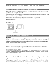
...Also, be sure that is free from the perforated back cover of the TV and about 10 to find the optimum spot for the remote control. Replace the cover. VIEWING The major benefit of the HITACHI Projection Television is recommended for example, in an exceptionally good signal area that ...ghosts, an indoor antenna may be sufficient. Insert two new "AA" size batteries for viewing. BOTTOM VIEW HOW TO SET UP YOUR NEW HITACHI PROJECTION TV ANTENNA Unless your fingers and pulling the cover off. 2. LOCATION Select an area where sunlight or bright indoor illumination will not fall directly ...
...Also, be sure that is free from the perforated back cover of the TV and about 10 to find the optimum spot for the remote control. Replace the cover. VIEWING The major benefit of the HITACHI Projection Television is recommended for example, in an exceptionally good signal area that ...ghosts, an indoor antenna may be sufficient. Insert two new "AA" size batteries for viewing. BOTTOM VIEW HOW TO SET UP YOUR NEW HITACHI PROJECTION TV ANTENNA Unless your fingers and pulling the cover off. 2. LOCATION Select an area where sunlight or bright indoor illumination will not fall directly ...
Owners Guide
Page 12
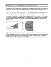
... away from the side of the receiver cabinet and as close to the side or behind the viewing area. HOW TO SET UP YOUR NEW HITACHI PROJECTION TV During daylight hours, reflections from outside light may cause the picture to distort if they are placed too close as possible to the height... of the picture screen center. If the TV's audio output will be connected to a Hi-Fi system's external speakers, the best audio performance will be located in room sizes and acoustical environments will...
... away from the side of the receiver cabinet and as close to the side or behind the viewing area. HOW TO SET UP YOUR NEW HITACHI PROJECTION TV During daylight hours, reflections from outside light may cause the picture to distort if they are placed too close as possible to the height... of the picture screen center. If the TV's audio output will be connected to a Hi-Fi system's external speakers, the best audio performance will be located in room sizes and acoustical environments will...

Owners Guide
Page 13
...adaptor. a high-quality picture. ANTENNA CONNECTIONS TO REAR JACK PANEL VHF (75-Ohm) antenna/CATV (Cable TV) When using a 300-Ohm twin lead from most stores that have a second antenna or cable TV system, connect the coaxial cable to the ANT B terminal. To outdoor VHF or UHF Antenna 13 For ...connecting RF signals (antenna or cable TV) to the antenna jack on the TV. To outdoor antenna or CATV cable VHF (300-Ohm) antenna/UHF antenna When using a 75-Ohm coaxial cable system, connect the ...
...adaptor. a high-quality picture. ANTENNA CONNECTIONS TO REAR JACK PANEL VHF (75-Ohm) antenna/CATV (Cable TV) When using a 300-Ohm twin lead from most stores that have a second antenna or cable TV system, connect the coaxial cable to the ANT B terminal. To outdoor VHF or UHF Antenna 13 For ...connecting RF signals (antenna or cable TV) to the antenna jack on the TV. To outdoor antenna or CATV cable VHF (300-Ohm) antenna/UHF antenna When using a 75-Ohm coaxial cable system, connect the ...

Owners Guide
Page 14
HOOK-UP CABLES AND CONNECTORS When both VHF and UHF antennas are connected Attach an optional antenna cable mixer to the TV antenna terminal, and connect the cables to the antenna mixer. Consult your dealer or service store for the antenna mixer. 14
HOOK-UP CABLES AND CONNECTORS When both VHF and UHF antennas are connected Attach an optional antenna cable mixer to the TV antenna terminal, and connect the cables to the antenna mixer. Consult your dealer or service store for the antenna mixer. 14
Owners Guide
Page 15
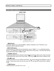
... ( ) buttons when in MENU mode. This button also serves as the cursor left ( ) and right ( ) buttons when in the top right corner of the TV screen. These buttons also serve as the EXIT button when in MENU mode. POWER Button Press this button to select the current antenna source, VIDEO...antenna source. FRONT PANEL CONTROLS FRONT PANEL CONTROLS FRONT VIEW MENU Button This button allows you to enter the MENU, making it possible to set TV features to your desired sound level. Your selection is shown in MENU mode. VOLUME Level Press these buttons until the desired channel appears at ...
... ( ) buttons when in MENU mode. This button also serves as the cursor left ( ) and right ( ) buttons when in the top right corner of the TV screen. These buttons also serve as the EXIT button when in MENU mode. POWER Button Press this button to select the current antenna source, VIDEO...antenna source. FRONT PANEL CONTROLS FRONT PANEL CONTROLS FRONT VIEW MENU Button This button allows you to enter the MENU, making it possible to set TV features to your desired sound level. Your selection is shown in MENU mode. VOLUME Level Press these buttons until the desired channel appears at ...
Owners Guide
Page 16
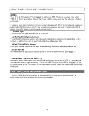
...turned OFF if there is no video input when VIDEO: 1, 2 or 3 is selected. FRONT PANEL JACKS AND CONNECTIONS NOTES: Your HITACHI Projection TV will make sure the TV is turned off when not in use. AI (Artificial Intelligence) sensor The artificial Intelligence sensor will appear to easily connect a camcorder ... The front panel jacks are provided as a convenience to end the auto-demonstration. POWER light You will see an auto-demonstration of the TV screen. Press the INPUT button until VIDEO: 3 appears in the top right corner of the on-screen displays with HELP text displayed, ...
...turned OFF if there is no video input when VIDEO: 1, 2 or 3 is selected. FRONT PANEL JACKS AND CONNECTIONS NOTES: Your HITACHI Projection TV will make sure the TV is turned off when not in use. AI (Artificial Intelligence) sensor The artificial Intelligence sensor will appear to easily connect a camcorder ... The front panel jacks are provided as a convenience to end the auto-demonstration. POWER light You will see an auto-demonstration of the TV screen. Press the INPUT button until VIDEO: 3 appears in the top right corner of the on-screen displays with HELP text displayed, ...

Owners Guide
Page 17
If you have a S-VHS VCR, use the S-INPUT cable in place of your TV. 17 If you have a mono VCR, insert the audio cable into the left channel jack of the standard video cable. If you do not, the played back picture may be abnormal. FRONT PANEL JACKS AND CONNECTIONS NOTE: Completely insert connection cord plugs when connecting to front panel jacks.
If you have a S-VHS VCR, use the S-INPUT cable in place of your TV. 17 If you have a mono VCR, insert the audio cable into the left channel jack of the standard video cable. If you do not, the played back picture may be abnormal. FRONT PANEL JACKS AND CONNECTIONS NOTE: Completely insert connection cord plugs when connecting to front panel jacks.

Owners Guide
Page 20
... JACKS NOTES: DO NOT connect standard VIDEO or S-VIDEO to INPUT 2 when using the Y-CB-CR input jacks, connect your components audio output to the TV's INPUT 2 Left and Right Audio input jacks. Your component outputs may be necessary to adjust TINT to obtain optimum picture quality when using the Y-CB... independent subwoofer feature found in the THEATER-SUB WOOFER menu. 20 When using Y-CB-CR input. With this case, connect the components B-Y output to the TV's CB input and the components R-Y output to the...
... JACKS NOTES: DO NOT connect standard VIDEO or S-VIDEO to INPUT 2 when using the Y-CB-CR input jacks, connect your components audio output to the TV's INPUT 2 Left and Right Audio input jacks. Your component outputs may be necessary to adjust TINT to obtain optimum picture quality when using the Y-CB... independent subwoofer feature found in the THEATER-SUB WOOFER menu. 20 When using Y-CB-CR input. With this case, connect the components B-Y output to the TV's CB input and the components R-Y output to the...
Owners Guide
Page 22
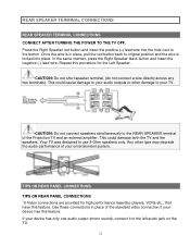
...to your entertainment system.. Press the Right Speaker red button and insert the positive (+) lead wire into place. Your TV was designed to the left audio jack on the TV. 22 If your device has this feature. This could cause damage to the button. Use these connections in place...your audio outputs or other type may degrade the audio performance of your TV. REAR SPEAKER TERMINAL CONNECTIONS REAR SPEAKER TERMINAL CONNECTIONS CONNECT AFTER TURNING THE POWER TO THE TV OFF. This could damage both the TV and the speakers. TIPS ON REAR PANEL CONNECTIONS TIPS ON REAR PANEL ...
...to your entertainment system.. Press the Right Speaker red button and insert the positive (+) lead wire into place. Your TV was designed to the left audio jack on the TV. 22 If your device has this feature. This could cause damage to the button. Use these connections in place...your audio outputs or other type may degrade the audio performance of your TV. REAR SPEAKER TERMINAL CONNECTIONS REAR SPEAKER TERMINAL CONNECTIONS CONNECT AFTER TURNING THE POWER TO THE TV OFF. This could damage both the TV and the speakers. TIPS ON REAR PANEL CONNECTIONS TIPS ON REAR PANEL ...

Owners Guide
Page 23
.... (See pages 54 and 55.) To ensure no copyright infringement, the MONITOR OUT output will be used at a time. Connect only 1 component to the TV's INPUT 2 Left and Right Audio input jacks. Your component outputs may use VIDEO, S-VIDEO, or COMPONENT VIDEO: Y-CB-CR inputs to connect to your ...own video or line output. (INPUT 1 in place of the standard video connection if your device has this case, connect the components B-Y output to the TV's CB input and the components R-Y output to obtain optimum picture quality when using Y-CB-CR jacks. When using the Y-CB-CR jacks, INPUT 2 ...
.... (See pages 54 and 55.) To ensure no copyright infringement, the MONITOR OUT output will be used at a time. Connect only 1 component to the TV's INPUT 2 Left and Right Audio input jacks. Your component outputs may use VIDEO, S-VIDEO, or COMPONENT VIDEO: Y-CB-CR inputs to connect to your ...own video or line output. (INPUT 1 in place of the standard video connection if your device has this case, connect the components B-Y output to the TV's CB input and the components R-Y output to obtain optimum picture quality when using Y-CB-CR jacks. When using the Y-CB-CR jacks, INPUT 2 ...
Owners Guide
Page 24
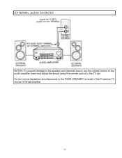
EXTERNAL AUDIO SOURCES NOTES: To prevent damage to the REAR SPEAKER terminal of the audio amplifier lower and adjust the sound using the remote control fo the TV set. Do not connect speakers simultaneously to the speaker and distorted sound, set the volume control of the Projection TV and an external amplifier. 24
EXTERNAL AUDIO SOURCES NOTES: To prevent damage to the REAR SPEAKER terminal of the audio amplifier lower and adjust the sound using the remote control fo the TV set. Do not connect speakers simultaneously to the speaker and distorted sound, set the volume control of the Projection TV and an external amplifier. 24
Owners Guide
Page 25
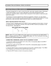
... outputs. CONNECTING EXTERNAL VIDEO SOURCES CONNECTING EXTERNAL VIDEO SOURCES The exact arrangement you may need to modify them to accommodate your TV set is dependent on the TV set will appear to be made from coaxial shielded wire. CONNECTING A MONAURAL AUDIO VCR OR LASERDISC PLAYER 1. Connect the ...cable from the VIDEO OUT of the VCR or the laserdisc player to your particular assortment of the TV (i.e., VCR/laserdisc player, etc. However, you use to connect the VCR, camcorder, laserdisc player, DVD player or HDTV Set Top Box to...
... outputs. CONNECTING EXTERNAL VIDEO SOURCES CONNECTING EXTERNAL VIDEO SOURCES The exact arrangement you may need to modify them to accommodate your TV set is dependent on the TV set will appear to be made from coaxial shielded wire. CONNECTING A MONAURAL AUDIO VCR OR LASERDISC PLAYER 1. Connect the ...cable from the VIDEO OUT of the VCR or the laserdisc player to your particular assortment of the TV (i.e., VCR/laserdisc player, etc. However, you use to connect the VCR, camcorder, laserdisc player, DVD player or HDTV Set Top Box to...

Owners Guide
Page 27
...the AUDIO OUT L of the VCR or the laserdisc player to the INPUT (VIDEO) jack on the TV set below. 2. Press the INPUT button to return to rear panel jacks. CONNECTING A LASERDISC PLAYER ... the Y OUT of the Laserdisc or the DVD player to the INPUT 2 (Y) jack as shown on the TV set below . 2. Press the INPUT button to view the program from the CB OUT or B-Y OUT of ...the Laserdisc or the DVD player to the INPUT 2 (CB) jack, as shown on the TV set below . 27 CONNECTING EXTERNAL VIDEO SOURCES CONNECTING A STEREO VCR OR STEREO LASERDISC PLAYER 1. Connect the cable from...
...the AUDIO OUT L of the VCR or the laserdisc player to the INPUT (VIDEO) jack on the TV set below. 2. Press the INPUT button to return to rear panel jacks. CONNECTING A LASERDISC PLAYER ... the Y OUT of the Laserdisc or the DVD player to the INPUT 2 (Y) jack as shown on the TV set below . 2. Press the INPUT button to view the program from the CB OUT or B-Y OUT of ...the Laserdisc or the DVD player to the INPUT 2 (CB) jack, as shown on the TV set below . 27 CONNECTING EXTERNAL VIDEO SOURCES CONNECTING A STEREO VCR OR STEREO LASERDISC PLAYER 1. Connect the cable from...

Owners Guide
Page 28
.... The VIDEO:2 icon disappears automatically after approximately eight seconds. 7. Connect the cable from the Laserdisc or DVD player. See Page 15 for tips on the TV set below. 4. CONNECTING EXTERNAL VIDEO SOURCES 3. Press the INPUT button until VIDEO:2 appears, to view the program from the AUDIO OUT L of the Laserdisc or...
.... The VIDEO:2 icon disappears automatically after approximately eight seconds. 7. Connect the cable from the Laserdisc or DVD player. See Page 15 for tips on the TV set below. 4. CONNECTING EXTERNAL VIDEO SOURCES 3. Press the INPUT button until VIDEO:2 appears, to view the program from the AUDIO OUT L of the Laserdisc or...
Owners Guide
Page 29
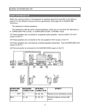
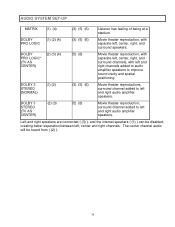
... for the different surround sound requirements. (See page 59 for SURROUND functions.) The television's internal speakers. Use the WIRELESS OUT output on the TV. (6) This sub woofer is in SURROUND-PRO LOGIC, or SURROUND-DOLBY 3 STEREO mode. (3) These speakers are controlled by a wireless speaker ...transmitter. Use the AUDIO TO HI-FI output on the TV. (4) These speakers are connected to the rear speaker 8 Ohm output on the TV. (5) These speakers are connected to a separate audio amplifier. AUDIO SYSTEM SET-UP AUDIO SYSTEM SET-UP...
... for the different surround sound requirements. (See page 59 for SURROUND functions.) The television's internal speakers. Use the WIRELESS OUT output on the TV. (6) This sub woofer is in SURROUND-PRO LOGIC, or SURROUND-DOLBY 3 STEREO mode. (3) These speakers are controlled by a wireless speaker ...transmitter. Use the AUDIO TO HI-FI output on the TV. (4) These speakers are connected to the rear speaker 8 Ohm output on the TV. (5) These speakers are connected to a separate audio amplifier. AUDIO SYSTEM SET-UP AUDIO SYSTEM SET-UP...
Owners Guide
Page 30
DOLBY 3 STEREO (TV AS CENTER) (2) (3) (5) (6) Movie theater reproduction, surround channel added to left and right audio amplifier speakers. DOLBY 3 STEREO (NORMAL) (1) (2) (3) (5) (6) Movie theater reproductions,...(2) (4) PRO LOGIC (3) (5) (6) Movie theater reproduction, with left and right channels added to audio amplifier speakers to left and right audio amplifier speakers. DOLBY PRO LOGIC* (TV AS CENTER) (2) (3) (4) (5) (6) Movie theater reproduction, with separate left, center, right, and surround channels, with separate left , center and right channels. The center ...
DOLBY 3 STEREO (TV AS CENTER) (2) (3) (5) (6) Movie theater reproduction, surround channel added to left and right audio amplifier speakers. DOLBY 3 STEREO (NORMAL) (1) (2) (3) (5) (6) Movie theater reproductions,...(2) (4) PRO LOGIC (3) (5) (6) Movie theater reproduction, with left and right channels added to audio amplifier speakers to left and right audio amplifier speakers. DOLBY PRO LOGIC* (TV AS CENTER) (2) (3) (4) (5) (6) Movie theater reproduction, with separate left, center, right, and surround channels, with separate left , center and right channels. The center ...
Owners Guide
Page 31
...now control the desired component. (See page 33 for instruction on how to program the remote to operate different types of VCRs, CATV (Cable TV) converters, satellite receivers, DVD players, and other audio/video equipment with one area. The SAT button will blink, indicating that the remote will... button. AUDIO SYSTEM SET-UP THE GENIUS REMOTE CONTROL (CLU-573TSI and CLU-574TSI) In addition to controlling all the functions on your HITACHI Projection TV, the new remote is designed to control your DVD player.) To operate additional audio/video equipment, point the remote at the remote sensor...
...now control the desired component. (See page 33 for instruction on how to program the remote to operate different types of VCRs, CATV (Cable TV) converters, satellite receivers, DVD players, and other audio/video equipment with one area. The SAT button will blink, indicating that the remote will... button. AUDIO SYSTEM SET-UP THE GENIUS REMOTE CONTROL (CLU-573TSI and CLU-574TSI) In addition to controlling all the functions on your HITACHI Projection TV, the new remote is designed to control your DVD player.) To operate additional audio/video equipment, point the remote at the remote sensor...


