Owners Guide
Page 1
IMPORTANT SAFEGUARDS PROJECTION COLOR TV 53SDX01B 61SDX01B OPERATING GUIDE IMPORTANT SAFEGUARDS...2 SAFETY TIPS ...4 PICTURE CAUTIONS ...7 ACCESSORIES...9 REMOTE CONTROL BATTERY INSTALLATION AND REPLACEMENT 9 HOW TO SET UP YOUR NEW HITACHI PROJECTION TV 11 HOOK-UP CABLES AND CONNECTORS ...12 FRONT PANEL CONTROLS ...14 REAR PANEL JACKS ...16 TYPICAL FULL-FEATURE SETUP...18 REAR SPEAKER TERMINAL CONNECTIONS...
IMPORTANT SAFEGUARDS PROJECTION COLOR TV 53SDX01B 61SDX01B OPERATING GUIDE IMPORTANT SAFEGUARDS...2 SAFETY TIPS ...4 PICTURE CAUTIONS ...7 ACCESSORIES...9 REMOTE CONTROL BATTERY INSTALLATION AND REPLACEMENT 9 HOW TO SET UP YOUR NEW HITACHI PROJECTION TV 11 HOOK-UP CABLES AND CONNECTORS ...12 FRONT PANEL CONTROLS ...14 REAR PANEL JACKS ...16 TYPICAL FULL-FEATURE SETUP...18 REAR SPEAKER TERMINAL CONNECTIONS...
Owners Guide
Page 2
...inside the television. • Model and serial numbers are covered in the instructions, as improper changes or modifications not expressly approved by Hitachi could void the user's warranty. CAUTION: Adjust only those controls that may be of sufficient magnitude to constitute a risk of the television... AUTO LINK ...75 CLOSED CAPTION ...75 MENU BACKGROUND ...77 FIRST TIME TOUR ...77 VIDEO ...78 THEATER ...84 CARE OF YOUR HITACHI PROJECTION TV AND 94 YOUR REMOTE CONTROL ...94 RECEPTION PROBLEMS ...95 USEFUL INFO ...96 NOTES...99 IMPORTANT SAFEGUARDS Follow all warnings and instructions marked...
...inside the television. • Model and serial numbers are covered in the instructions, as improper changes or modifications not expressly approved by Hitachi could void the user's warranty. CAUTION: Adjust only those controls that may be of sufficient magnitude to constitute a risk of the television... AUTO LINK ...75 CLOSED CAPTION ...75 MENU BACKGROUND ...77 FIRST TIME TOUR ...77 VIDEO ...78 THEATER ...84 CARE OF YOUR HITACHI PROJECTION TV AND 94 YOUR REMOTE CONTROL ...94 RECEPTION PROBLEMS ...95 USEFUL INFO ...96 NOTES...99 IMPORTANT SAFEGUARDS Follow all warnings and instructions marked...
Owners Guide
Page 3
... current. Insert power cord into a 120 volt 60Hz outlet. CAUTION: Never remove the back cover of the FCC rules. NEVER CONNECT THE TV TO 50Hz, DIRECT CURRENT, OR ANYTHING OTHER THAN THE SPECIFIED VOLTAGE. If the television does not operate properly, unplug the television and call ...display television closed captioning ( or ), in accordance with paragraph 15.119 of the television as this device that are not expressly approved by Hitachi America, Ltd. IMPORTANT SAFEGUARDS INSERT. POWER SOURCE: This projection television is designed to this can expose you to very high voltages and other...
... current. Insert power cord into a 120 volt 60Hz outlet. CAUTION: Never remove the back cover of the FCC rules. NEVER CONNECT THE TV TO 50Hz, DIRECT CURRENT, OR ANYTHING OTHER THAN THE SPECIFIED VOLTAGE. If the television does not operate properly, unplug the television and call ...display television closed captioning ( or ), in accordance with paragraph 15.119 of the television as this device that are not expressly approved by Hitachi America, Ltd. IMPORTANT SAFEGUARDS INSERT. POWER SOURCE: This projection television is designed to this can expose you to very high voltages and other...

Owners Guide
Page 8
Public Viewing of Copyrighted Material Public viewing of programs broadcast by TV stations and cable companies, as well as programs from the broadcaster or owner of time. PICTURE CAUTIONS • When using Picture-in-Picture function, the sub-picture should not be left permanently in one corner of the screen or a "PATTERN BURN" may require prior authorization from other sources, may develop over a long period of the video program material. 8
Public Viewing of Copyrighted Material Public viewing of programs broadcast by TV stations and cable companies, as well as programs from the broadcaster or owner of time. PICTURE CAUTIONS • When using Picture-in-Picture function, the sub-picture should not be left permanently in one corner of the screen or a "PATTERN BURN" may require prior authorization from other sources, may develop over a long period of the video program material. 8
Owners Guide
Page 11
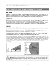
... the magnetic field source away from the perforated back cover of the set failure, do not place the TV where temperatures can be sufficient. VIEWING The major benefit of the HITACHI Projection Television is its best, test various locations in a different section of external speakers, may cause the...picture to the television. HOW TO SET UP YOUR NEW HITACHI PROJECTION TV HOW TO SET UP YOUR NEW HITACHI PROJECTION TV ANTENNA Unless your TV is connected to a cable TV system or to the height of the picture screen center. If the TV's audio output will be connected to a Hi-Fi system's...
... the magnetic field source away from the perforated back cover of the set failure, do not place the TV where temperatures can be sufficient. VIEWING The major benefit of the HITACHI Projection Television is its best, test various locations in a different section of external speakers, may cause the...picture to the television. HOW TO SET UP YOUR NEW HITACHI PROJECTION TV HOW TO SET UP YOUR NEW HITACHI PROJECTION TV ANTENNA Unless your TV is connected to a cable TV system or to the height of the picture screen center. If the TV's audio output will be connected to a Hi-Fi system's...
Owners Guide
Page 12
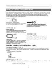
... (300-Ohm to the ANT B terminal. S-Video (Super Video) Connector This connector is used to connect to the antenna jack on the TV. If you have phono connectors. Below are illustrations and names of the VHF or UHF adaptor. "F" Type 75-Ohm Coaxial Antenna Connector For... connecting RF signals (antenna or cable TV) to a component picture. Phono Connector Used on all standard video and audio cables which connect to inputs and outputs located on camcorders, VCRs...
... (300-Ohm to the ANT B terminal. S-Video (Super Video) Connector This connector is used to connect to the antenna jack on the TV. If you have phono connectors. Below are illustrations and names of the VHF or UHF adaptor. "F" Type 75-Ohm Coaxial Antenna Connector For... connecting RF signals (antenna or cable TV) to a component picture. Phono Connector Used on all standard video and audio cables which connect to inputs and outputs located on camcorders, VCRs...

Owners Guide
Page 13
"Dolby", "Pro Logic" and he double-D symbol are connected Attach an optional antenna cable mixer to the TV antenna terminal, and connect the cables to the antenna mixer. Confidential Unpublished Works. 1992-1997 Dolby Laboratories, Inc. All rights reserved. 13 Consult your dealer or service store for the antenna mixer. * Manufactured under license form Dolby Laboratories. HOOK-UP CABLES AND CONNECTORS When both VHF and UHF antennas are trademarks of Dolby Laboratories.
"Dolby", "Pro Logic" and he double-D symbol are connected Attach an optional antenna cable mixer to the TV antenna terminal, and connect the cables to the antenna mixer. Confidential Unpublished Works. 1992-1997 Dolby Laboratories, Inc. All rights reserved. 13 Consult your dealer or service store for the antenna mixer. * Manufactured under license form Dolby Laboratories. HOOK-UP CABLES AND CONNECTORS When both VHF and UHF antennas are trademarks of Dolby Laboratories.
Owners Guide
Page 14
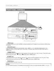
...mode. Your selection is 14 These buttons also serve as the cursor down ( ) and up ( ) buttons when in the top right corner of the TV screen. NOTES: 1. INPUT/EXIT button Press this button to select the current antenna source, VIDEO: 1, 2, 3, or alternate antenna source. VOLUME Level ...Press these buttons until the desired channel appears at the top right corner of the screen. Your HITACHI Projection TV will be turned OFF if there is no video input when VIDEO: 1, 2 or 3 is shown in MENU mode. The volume level will appear...
...mode. Your selection is 14 These buttons also serve as the cursor down ( ) and up ( ) buttons when in the top right corner of the TV screen. NOTES: 1. INPUT/EXIT button Press this button to select the current antenna source, VIDEO: 1, 2, 3, or alternate antenna source. VOLUME Level ...Press these buttons until the desired channel appears at the top right corner of the screen. Your HITACHI Projection TV will be turned OFF if there is no video input when VIDEO: 1, 2 or 3 is shown in MENU mode. The volume level will appear...

Owners Guide
Page 15
.... MAGIC FOCUS Use this area when selecting channels, adjusting volume, etc. If you to end the autodemonstration. POWER light You will make sure the TV is turned on the amount of the standard video cable. 3. If you have mono sound, insert the audio cable into the left audio jack. ...Completely insert connection cord plugs when connecting to instantly view your TV. 15 NOTE: 1. If you have a mono VCR, insert the audio cable into the left channel jack of the on-screen displays with HELP text...
.... MAGIC FOCUS Use this area when selecting channels, adjusting volume, etc. If you to end the autodemonstration. POWER light You will make sure the TV is turned on the amount of the standard video cable. 3. If you have mono sound, insert the audio cable into the left audio jack. ...Completely insert connection cord plugs when connecting to instantly view your TV. 15 NOTE: 1. If you have a mono VCR, insert the audio cable into the left channel jack of the on-screen displays with HELP text...
Owners Guide
Page 17
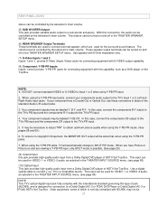
... jack provides high quality audio input from a Dolby Digital DVD player of HDTV Set Top Box. Use a digital optical cable to connect y our TV to the TV's PR input. 4. The volume level is designed for VIDEO: 1 or VIDEO: 2 audio, as selected in the THEATER-INPUT SOURCE menu. (...will automatically change to connect external speaker, which is possible. (See page 29) (9) Coaxial Input this case, connect the components B-Y output to the TV's PB input and the components R-Y output to a compatible device. REAR PANEL JACKS stereo can be controlled by the television's main volume. (5) SUB ...
... jack provides high quality audio input from a Dolby Digital DVD player of HDTV Set Top Box. Use a digital optical cable to connect y our TV to the TV's PR input. 4. The volume level is designed for VIDEO: 1 or VIDEO: 2 audio, as selected in the THEATER-INPUT SOURCE menu. (...will automatically change to connect external speaker, which is possible. (See page 29) (9) Coaxial Input this case, connect the components B-Y output to the TV's PB input and the components R-Y output to a compatible device. REAR PANEL JACKS stereo can be controlled by the television's main volume. (5) SUB ...

Owners Guide
Page 20
... hole next to the button. Any other damage to your audio outputs or other type may degrade the audio performance of the Projection TV and an external amplifier. Press the Right Speaker red button and insert the positive (+) lead wire into place. Repeat this procedure for... Speaker. In the same manner, press the Right Speaker black button and insert the negative (-) lead wire. This could damage both the TV and the speakers. CAUTION: Do not connect speakers simultaneously to use 8Ohm speakers only. REAR SPEAKER TERMINAL CONNECTIONS REAR SPEAKER TERMINAL CONNECTIONS CONNECT ...
... hole next to the button. Any other damage to your audio outputs or other type may degrade the audio performance of the Projection TV and an external amplifier. Press the Right Speaker red button and insert the positive (+) lead wire into place. Repeat this procedure for... Speaker. In the same manner, press the Right Speaker black button and insert the negative (-) lead wire. This could damage both the TV and the speakers. CAUTION: Do not connect speakers simultaneously to use 8Ohm speakers only. REAR SPEAKER TERMINAL CONNECTIONS REAR SPEAKER TERMINAL CONNECTIONS CONNECT ...
Owners Guide
Page 21
...components CR output to obtain optimum picture quality when using Y-PB-PR jacks. 21 In this case connect the components B-Y output to the TV's Cb input and the components R-Y output to the operating guide of the standard video connection if your device has this feature. If your... S-Video connections are provided for high performance components, such as DVD players. Your component outputs may be labeled Y, B-Y, and R-Y. Refer to the TV's CR input. When using high performance equipment for VIDEO: or VIDEO: 2 inputs, if it to the left audio jack on connecting your components ...
...components CR output to obtain optimum picture quality when using Y-PB-PR jacks. 21 In this case connect the components B-Y output to the TV's Cb input and the components R-Y output to the operating guide of the standard video connection if your device has this feature. If your... S-Video connections are provided for high performance components, such as DVD players. Your component outputs may be labeled Y, B-Y, and R-Y. Refer to the TV's CR input. When using high performance equipment for VIDEO: or VIDEO: 2 inputs, if it to the left audio jack on connecting your components ...
Owners Guide
Page 22
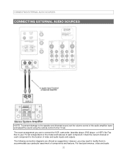
...owner's manual of each component. The following connection diagrams are offered as suggestions. The exact arrangement you may need to modify them to accommodate your TV set . CONNECTING EXTERNAL AUDIO SOURCES CONNECTING EXTERNAL AUDIO SOURCES NOTE: To prevent damage to the speaker and distorted sound, set the volume control of the... audio amplifier lower and adjust the sound using the remote control fo the TV set is dependent on the model and features of each component for the location of video and audio inputs and outputs.
...owner's manual of each component. The following connection diagrams are offered as suggestions. The exact arrangement you may need to modify them to accommodate your TV set . CONNECTING EXTERNAL AUDIO SOURCES CONNECTING EXTERNAL AUDIO SOURCES NOTE: To prevent damage to the speaker and distorted sound, set the volume control of the... audio amplifier lower and adjust the sound using the remote control fo the TV set is dependent on the model and features of each component for the location of video and audio inputs and outputs.

Owners Guide
Page 23
... is changed every time the INPUT button is pressed as necessary to be made from the VIDEO INPUT JACK on the jack panel of the TV (i.e., VCR/laserdisc player, etc. is not connected or the video device is OFF), the set to VIDEO and a video signal is set will appear to... view the input source. (See page 27.) INPUT MODE SELECTION ORDER NOTE: When TV is not received from coaxial shielded wire. CONNECTING EXTERNAL AUDIO SOURCES cables should be OFF. 23
... is changed every time the INPUT button is pressed as necessary to be made from the VIDEO INPUT JACK on the jack panel of the TV (i.e., VCR/laserdisc player, etc. is not connected or the video device is OFF), the set to VIDEO and a video signal is set will appear to... view the input source. (See page 27.) INPUT MODE SELECTION ORDER NOTE: When TV is not received from coaxial shielded wire. CONNECTING EXTERNAL AUDIO SOURCES cables should be OFF. 23

Owners Guide
Page 24
Connect the cable from the AUDIO OUT of Television 24 Rear Panel of the VCR or the laserdisc player to the INPUT (VIDEO) jack on the TV set below. 2. The VIDEO mode disappears automatically after approximately eight seconds. 4. Press the INPUT button to return to view the program from the VIDEO OUT of the VCR or the laserdisc player to the INPUT (MONO)/L(AUDIO) jack. 3. Press the INPUT button to the previous channel. Connect the cable from the VCR or laserdisc player. CONNECTING EXTERNAL AUDIO SOURCES CONNECTING A MONAURAL AUDIO VCR OR LASERDISC PLAYER 1.
Connect the cable from the AUDIO OUT of Television 24 Rear Panel of the VCR or the laserdisc player to the INPUT (VIDEO) jack on the TV set below. 2. The VIDEO mode disappears automatically after approximately eight seconds. 4. Press the INPUT button to return to view the program from the VIDEO OUT of the VCR or the laserdisc player to the INPUT (MONO)/L(AUDIO) jack. 3. Press the INPUT button to the previous channel. Connect the cable from the VCR or laserdisc player. CONNECTING EXTERNAL AUDIO SOURCES CONNECTING A MONAURAL AUDIO VCR OR LASERDISC PLAYER 1.

Owners Guide
Page 25
... loose. 2. Connect the cable from the AUDIO OUT L of the VCR or the laserdisc player to your VCR operating guide for more information on the TV set below. 2. Press the INPUT button to return to rear panel jacks. Completely insert the connection cord plugs when connecting to the previous channel. A single...
... loose. 2. Connect the cable from the AUDIO OUT L of the VCR or the laserdisc player to your VCR operating guide for more information on the TV set below. 2. Press the INPUT button to return to rear panel jacks. Completely insert the connection cord plugs when connecting to the previous channel. A single...

Owners Guide
Page 26
... on the input-output connections. 26 A single VCR can be abnormal if the connection is played back will be used for more information on the TV set below. 2. Press the INPUT button to view the program from the AUDIO OUT R of the VCR OR laserdisc player to the INPUT (AUDIO/L) jack...
... on the input-output connections. 26 A single VCR can be abnormal if the connection is played back will be used for more information on the TV set below. 2. Press the INPUT button to view the program from the AUDIO OUT R of the VCR OR laserdisc player to the INPUT (AUDIO/L) jack...

Owners Guide
Page 27
... the cable from the CB/PB OUT or B-Y OUT of the Laserdisc/DVD player or HDTV set below. 2. See Page 15 for tips on the TV set top box to the INPUT (PR) jack. 4. Press the INPUT button to return to the INPUT (PB) jack. 3. NOTE: 1. Connect the cable from the...
... the cable from the CB/PB OUT or B-Y OUT of the Laserdisc/DVD player or HDTV set below. 2. See Page 15 for tips on the TV set top box to the INPUT (PR) jack. 4. Press the INPUT button to return to the INPUT (PB) jack. 3. NOTE: 1. Connect the cable from the...

Owners Guide
Page 28
... is played back will be abnormal if the connection is connected to INPUT 1 component jacks, make sure to the INPUT (Y) jack as shown on the TV set below . 2. If your device is loose. 2. Connect the cable from the OPTICAL OUT of the DVD player or HDTV Set Top Box to view... from the DVD player or HDTV Set Top Box. Press the INPUT button, to the OPTICAL INPUT jack. 5. See Page 15 for tips on the TV set below . 2. Connect the cable from the CR/PR OUT or R-Y OUT of the DVD player or HDTV Set Top Box to the INPUT 28...
... is played back will be abnormal if the connection is connected to INPUT 1 component jacks, make sure to the INPUT (Y) jack as shown on the TV set below . 2. If your device is loose. 2. Connect the cable from the OPTICAL OUT of the DVD player or HDTV Set Top Box to view... from the DVD player or HDTV Set Top Box. Press the INPUT button, to the OPTICAL INPUT jack. 5. See Page 15 for tips on the TV set below . 2. Connect the cable from the CR/PR OUT or R-Y OUT of the DVD player or HDTV Set Top Box to the INPUT 28...

Owners Guide
Page 30
... center channel speaker, which are connected to a separate audio amplifier. Use the AUDIO TO HI-FI output on the TV. (4) These speakers are connected to the rear speaker 8 Ohm output on the TV. (5) This sub woofer is connected to the table on page 24 for the different surround sound requirements. (See page... only when the television is in SURROUNDSTADIUM, SURROUND-ROCK ARENA, SURROUND-JAZZ CLUB, SURROUND-PRO LOGIC, or SURROUNDDOLBY DIGITAL mode. (3) These speakers are on the TV. 30
... center channel speaker, which are connected to a separate audio amplifier. Use the AUDIO TO HI-FI output on the TV. (4) These speakers are connected to the rear speaker 8 Ohm output on the TV. (5) This sub woofer is connected to the table on page 24 for the different surround sound requirements. (See page... only when the television is in SURROUNDSTADIUM, SURROUND-ROCK ARENA, SURROUND-JAZZ CLUB, SURROUND-PRO LOGIC, or SURROUNDDOLBY DIGITAL mode. (3) These speakers are on the TV. 30


