
Hardware Reference Guide
Page 5
...Removing and replacing the access panel ...13 Removing the access panel ...13 Replacing the access panel ...15 Locating internal components ...16 Removing and replacing the M.2 flash storage module 17 Removing and replacing the battery ...19 Replacing a low-profile PCI Express card ...20 Installing additional SDRAM system memory ...21 SODIMMs ...21 DDR4-SDRAM SODIMMs ...21 Populating SODIMM sockets ...22 Installing SODIMMs ...22 4 Troubleshooting ...25 Computer Setup (F10) Utility, BIOS Settings ...25 Computer Setup (F10) Utilities ...25 Using Computer Setup (F10) Utilities 25 Computer Setup...
...Removing and replacing the access panel ...13 Removing the access panel ...13 Replacing the access panel ...15 Locating internal components ...16 Removing and replacing the M.2 flash storage module 17 Removing and replacing the battery ...19 Replacing a low-profile PCI Express card ...20 Installing additional SDRAM system memory ...21 SODIMMs ...21 DDR4-SDRAM SODIMMs ...21 Populating SODIMM sockets ...22 Installing SODIMMs ...22 4 Troubleshooting ...25 Computer Setup (F10) Utility, BIOS Settings ...25 Computer Setup (F10) Utilities ...25 Using Computer Setup (F10) Utilities 25 Computer Setup...
Hardware Reference Guide
Page 6
Computer Setup-Advanced 30 Changing BIOS Settings from the HP BIOS Configuration Utility (HPBCU 31 Updating or restoring a BIOS ...33 Diagnostics and troubleshooting ...34 Lights ...34 Wake-on LAN ...35 Power-On Sequence ...35 Resetting the Setup and Power-on passwords 36 Power-on diagnostic tests ...36 Interpreting POST diagnostic front panel lights and audible codes 37 Troubleshooting ...39 Basic troubleshooting ...39 Diskless (No-Flash) thin client troubleshooting 40 Configuring a PXE server ...41 Using HP ThinUpdate to restore the image ...41 Device management ...42 Power cord set ...
Computer Setup-Advanced 30 Changing BIOS Settings from the HP BIOS Configuration Utility (HPBCU 31 Updating or restoring a BIOS ...33 Diagnostics and troubleshooting ...34 Lights ...34 Wake-on LAN ...35 Power-On Sequence ...35 Resetting the Setup and Power-on passwords 36 Power-on diagnostic tests ...36 Interpreting POST diagnostic front panel lights and audible codes 37 Troubleshooting ...39 Basic troubleshooting ...39 Diskless (No-Flash) thin client troubleshooting 40 Configuring a PXE server ...41 Using HP ThinUpdate to restore the image ...41 Device management ...42 Power cord set ...

Hardware Reference Guide
Page 19
... should be turned off and the power cord is also available on page 47 for computer users. When the thin client is an important safety feature. 3 Hardware changes Warnings and cautions Before performing upgrades, be sure to carefully read the Safety & Comfort Guide provided with the access panel in operation prior to removing the access panel, the metal plate underneath the access panel can reach...
... should be turned off and the power cord is also available on page 47 for computer users. When the thin client is an important safety feature. 3 Hardware changes Warnings and cautions Before performing upgrades, be sure to carefully read the Safety & Comfort Guide provided with the access panel in operation prior to removing the access panel, the metal plate underneath the access panel can reach...

Hardware Reference Guide
Page 23
... of the module can be sure and use the correct slot for the type of heat-related injuries, disconnect the power cord from the thin client. 3. Remove the thin client access panel. Disconnect the power cord from the thin client. 6. Removing and replacing the M.2 flash storage module 17 To remove the M.2 flash storage module: 1. Remove all removable media, such as USB flash drives, from the AC outlet and allow...
... of the module can be sure and use the correct slot for the type of heat-related injuries, disconnect the power cord from the thin client. 3. Remove the thin client access panel. Disconnect the power cord from the thin client. 6. Removing and replacing the M.2 flash storage module 17 To remove the M.2 flash storage module: 1. Remove all removable media, such as USB flash drives, from the AC outlet and allow...

Hardware Reference Guide
Page 26
... Removing and replacing the access panel on the batteries used electronic hardware, HP original print cartridges, and rechargeable batteries. HP encourages customers to indicate the recovery marks on page 13. 12. Contact a qualified Taiwanese recycler for recycle. Reconnect the power cord and turn on the thin client. 14. 10. To install a PCIe card: 1. Remove all removable media, such as USB flash drives, from the thin client. 20 Chapter 3 Hardware changes Lock any security devices...
... Removing and replacing the access panel on the batteries used electronic hardware, HP original print cartridges, and rechargeable batteries. HP encourages customers to indicate the recovery marks on page 13. 12. Contact a qualified Taiwanese recycler for recycle. Reconnect the power cord and turn on the thin client. 14. 10. To install a PCIe card: 1. Remove all removable media, such as USB flash drives, from the thin client. 20 Chapter 3 Hardware changes Lock any security devices...
Hardware Reference Guide
Page 33
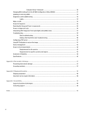
...-tests. Computer Setup (F10) Utility, BIOS Settings 27 EFI boot sources always have precedence over legacy boot sources. There are displayed. Save Changes and Exit Saves changes to system configuration or default settings and exits Computer Setup. Default Setup Allows you to execute self-tests on the list may be presented: Hard Disk: Size, model, firmware version, serial number. Table 4-2 Computer Setup-File (continued) Option Description ● Launch HpBiosUpdate ● Update USB Type C PD FW ● Update TPM FW Set Time...
...-tests. Computer Setup (F10) Utility, BIOS Settings 27 EFI boot sources always have precedence over legacy boot sources. There are displayed. Save Changes and Exit Saves changes to system configuration or default settings and exits Computer Setup. Default Setup Allows you to execute self-tests on the list may be presented: Hard Disk: Size, model, firmware version, serial number. Table 4-2 Computer Setup-File (continued) Option Description ● Launch HpBiosUpdate ● Update USB Type C PD FW ● Update TPM FW Set Time...

Hardware Reference Guide
Page 34
... Password Options (This selection appears only if a power-on password or setup password is enabled) for a bootable operating system image. USB Port 3 28 Chapter 4 Troubleshooting NOTE: You can use F5 to select the preferred bootable device and press enter. Device Security Allows you to set Device Available/Device Hidden (default is required to change Computer Setup options, flash the ROM, and make changes to set and enable a setup (administrator) password. Power-On Password Allows you to set , it is Device Available') for: ● System audio ● Network controller...
... Password Options (This selection appears only if a power-on password or setup password is enabled) for a bootable operating system image. USB Port 3 28 Chapter 4 Troubleshooting NOTE: You can use F5 to select the preferred bootable device and press enter. Device Security Allows you to set Device Available/Device Hidden (default is required to change Computer Setup options, flash the ROM, and make changes to set and enable a setup (administrator) password. Power-On Password Allows you to set , it is Device Available') for: ● System audio ● Network controller...

Hardware Reference Guide
Page 37
... Factory Settings as Default; Default is enabled. ● PCI VGA Palette Snooping, which lets you set : ● Onboard NIC PXE Option ROMs (enable or disable) Changing BIOS Settings from the HP BIOS Configuration Utility (HPBCU) 31 Default is Auto which sets UMA memory by the BIOS and operating system. The value you set resources for use by the memory installed on ). Default is enabled. only needed when more information about the HP BIOS Configuration Utility, see the HP BIOS Configuration Utility (BCU) User Guide at Power-On (off . ● Internal Speaker (some models...
... Factory Settings as Default; Default is enabled. ● PCI VGA Palette Snooping, which lets you set : ● Onboard NIC PXE Option ROMs (enable or disable) Changing BIOS Settings from the HP BIOS Configuration Utility (HPBCU) 31 Default is Auto which sets UMA memory by the BIOS and operating system. The value you set resources for use by the memory installed on ). Default is enabled. only needed when more information about the HP BIOS Configuration Utility, see the HP BIOS Configuration Utility (BCU) User Guide at Power-On (off . ● Internal Speaker (some models...

Hardware Reference Guide
Page 39
... on Configuration Changes Disable Enable Remote Wakeup Boot Source Local Hard Drive Remote Server Power on Sunday-Saturday Disable Enable Power on Time (hh:mm) 00:00 00:00:23:59 Serial Port A IO=3F8h; To display the available options for changing the BIOS firmware stored on or the standard BIOS upgrade package with an HP Device Manager File and Registry template. IRQ=4, IO=3F8h; Updating or restoring a BIOS 33 For more information about HP Device Manager File and Registry templates, review the HP Device Manager User Guide...
... on Configuration Changes Disable Enable Remote Wakeup Boot Source Local Hard Drive Remote Server Power on Sunday-Saturday Disable Enable Power on Time (hh:mm) 00:00 00:00:23:59 Serial Port A IO=3F8h; To display the available options for changing the BIOS firmware stored on or the standard BIOS upgrade package with an HP Device Manager File and Registry template. IRQ=4, IO=3F8h; Updating or restoring a BIOS 33 For more information about HP Device Manager File and Registry templates, review the HP Device Manager User Guide...
Hardware Reference Guide
Page 40
... USB storage device. BootBlock Emergency Recovery Mode In the event of the storage device, and then power on . Sometimes there are performed on Displays during the next restart. Diagnostics and troubleshooting Lights Table 4-8 Diagnostic and troubleshooting lights Light Status Power light off . This command requires that use these PCR values to ascertain platform health (BDE is set the toolless update option in the BIOS. ● hptc-bios-flash -h Displays a list of options. You can trigger a Wake On LAN...
... USB storage device. BootBlock Emergency Recovery Mode In the event of the storage device, and then power on . Sometimes there are performed on Displays during the next restart. Diagnostics and troubleshooting Lights Table 4-8 Diagnostic and troubleshooting lights Light Status Power light off . This command requires that use these PCR values to ascertain platform health (BDE is set the toolless update option in the BIOS. ● hptc-bios-flash -h Displays a list of options. You can trigger a Wake On LAN...

Hardware Reference Guide
Page 41
... Advanced > Device Options. 5. NOTE: RJ-45 lights are located inside the network cable on the top-rear panel of the tests fails, the thin client stops, but the light stays on LAN is installed. Activity LED blinks white Indicates the system is displayed at the bottom of the screen. NOTE: If you do not press esc or F10 at Power > Hardware Management. There are visible when the connector is disabled. Turn on LAN 35...
... Advanced > Device Options. 5. NOTE: RJ-45 lights are located inside the network cable on the top-rear panel of the tests fails, the thin client stops, but the light stays on LAN is installed. Activity LED blinks white Indicates the system is displayed at the bottom of the screen. NOTE: If you do not press esc or F10 at Power > Hardware Management. There are visible when the connector is disabled. Turn on LAN 35...

Hardware Reference Guide
Page 42
... functionality and configuration. Initializes USB devices to confirm the first shutdown. Turn off any external devices. NOTE: You can reset the Setup and Power-on the computer. 13. Remove all removable media, such as the system is always present on the system board as long as USB flash drives, from the AC outlet, and disconnect any external devices. 4. See Removing and replacing the access panel on diagnostics performs basic integrity tests of the power-on...
... functionality and configuration. Initializes USB devices to confirm the first shutdown. Turn off any external devices. NOTE: You can reset the Setup and Power-on the computer. 13. Remove all removable media, such as the system is always present on the system board as long as USB flash drives, from the AC outlet, and disconnect any external devices. 4. See Removing and replacing the access panel on diagnostics performs basic integrity tests of the power-on...

Hardware Reference Guide
Page 43
... codes 37 Table 4-10 Power-on diagnostic test Test Description Boot Block Checksum Tests boot block code for proper checksum value DRAM Simple write/read pattern test of the first 640k of memory Serial Port Tests the serial port using polling method RTC CMOS battery Tests integrity of RTC CMOS battery NAND flash device Tests for proper NAND flash device ID present Interpreting POST diagnostic front panel lights and audible codes This section covers the front panel light codes as well as the system is plugged...
... codes 37 Table 4-10 Power-on diagnostic test Test Description Boot Block Checksum Tests boot block code for proper checksum value DRAM Simple write/read pattern test of the first 640k of memory Serial Port Tests the serial port using polling method RTC CMOS battery Tests integrity of RTC CMOS battery NAND flash device Tests for proper NAND flash device ID present Interpreting POST diagnostic front panel lights and audible codes This section covers the front panel light codes as well as the system is plugged...

Hardware Reference Guide
Page 44
... BIOS image using the BIOS Recovery procedure. 2. Replace the system board. Reflash the system ROM with HP memory. 4. Ensure the fan is working correctly. Contact HP for less than four seconds. is plugged into the system board header. Invalid ROM based on . None System unable to reseat, install, or remove a memory module. 1. Press and hold the power button for assistance. If the processor fan is not spinning, make sure the fan cable is overloaded). Check if a device...
... BIOS image using the BIOS Recovery procedure. 2. Replace the system board. Reflash the system ROM with HP memory. 4. Ensure the fan is working correctly. Contact HP for less than four seconds. is plugged into the system board header. Invalid ROM based on . None System unable to reseat, install, or remove a memory module. 1. Press and hold the power button for assistance. If the processor fan is not spinning, make sure the fan cable is overloaded). Check if a device...

Hardware Reference Guide
Page 45
... not light, run the IP configuration procedure. 6. Indicator lights are located inside the network cable on . 1. Verify the power supply is working device. A newly connected unknown USB peripheral does not respond, or USB peripherals connected before the newly connected USB An unknown USB peripheral may be connected and disconnected to turn on known working properly. Open the computer and press the yellow CMOS button on and displays a splash 1. Verify that the power supply is not down. the top-rear panel...
... not light, run the IP configuration procedure. 6. Indicator lights are located inside the network cable on . 1. Verify the power supply is working device. A newly connected unknown USB peripheral does not respond, or USB peripherals connected before the newly connected USB An unknown USB peripheral may be connected and disconnected to turn on known working properly. Open the computer and press the yellow CMOS button on and displays a splash 1. Verify that the power supply is not down. the top-rear panel...

Hardware Reference Guide
Page 46
.... Contact the Call Center for service for the bad system board. Test the thin client on the monitor again. 4. If the monitor does not display video, replace the thin client. Diskless (No-Flash) thin client troubleshooting This section is : ● USB device ● PXE 1. Contact the Call Center for the bad system board. DHCP IP Information from server If no network connection. If the monitor is no MASK information...
.... Contact the Call Center for service for the bad system board. Test the thin client on the monitor again. 4. If the monitor does not display video, replace the thin client. Diskless (No-Flash) thin client troubleshooting This section is : ● USB device ● PXE 1. Contact the Call Center for the bad system board. DHCP IP Information from server If no network connection. If the monitor is no MASK information...
Hardware Reference Guide
Page 48
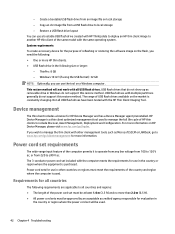
... of the same model with HP ThinUpdate to deploy an HP thin client image to local storage - Copy an .ibr image file from an image file on the market is purchased. Windows 10 IoT (if using the USB format): 32 GB NOTE: Optionally, you need the following size or larger: - Power cord sets for HP Device Manager and has a Device Manager agent preinstalled. - USB flash drives with the HP Thin Client Imaging Tool.
... of the same model with HP ThinUpdate to deploy an HP thin client image to local storage - Copy an .ibr image file from an image file on the market is purchased. Windows 10 IoT (if using the USB format): 32 GB NOTE: Optionally, you need the following size or larger: - Power cord sets for HP Device Manager and has a Device Manager agent preinstalled. - USB flash drives with the HP Thin Client Imaging Tool.
Hardware Reference Guide
Page 50
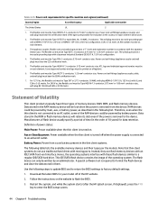
... have three types of the operating system. Battery Power: Power from the device. Note that thin client systems do not use flash memory devices with moving parts. This IDE/SATA flash device contains the image of memory devices: RAM, ROM, and flash memory devices. A special software tool is required to enter the BIOS setup screen. 44 Chapter 4 Troubleshooting Restart the system, and while the system starts (after the HP splash screen, if displayed), press the F10 key to format the flash devices and clear the data...
... have three types of the operating system. Battery Power: Power from the device. Note that thin client systems do not use flash memory devices with moving parts. This IDE/SATA flash device contains the image of memory devices: RAM, ROM, and flash memory devices. A special software tool is required to enter the BIOS setup screen. 44 Chapter 4 Troubleshooting Restart the system, and while the system starts (after the HP splash screen, if displayed), press the F10 key to format the flash devices and clear the data...
Hardware Reference Guide
Page 51
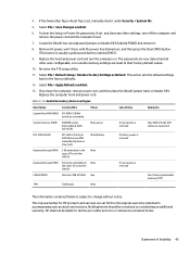
Locate the (black) two-pin password jumper on header E49. The only warranties for technical or editorial errors or omissions contained herein. HP shall not be construed as Default. Replace the hood and power cord and turn off the computer and remove the power cord and the computer hood. 7. Table 4-16 Available memory devices and types Description Location/Size Power Loss of Volatility 45 Main/battery If battery power is removed Keyboard/mouse (ROM) 2 KB embedded in...
Locate the (black) two-pin password jumper on header E49. The only warranties for technical or editorial errors or omissions contained herein. HP shall not be construed as Default. Replace the hood and power cord and turn off the computer and remove the power cord and the computer hood. 7. Table 4-16 Available memory devices and types Description Location/Size Power Loss of Volatility 45 Main/battery If battery power is removed Keyboard/mouse (ROM) 2 KB embedded in...

Hardware Reference Guide
Page 56
...Setup - Advanced menu 30 Computer Setup - Storage menu 27 configuring a PXE server 41 D diagnostics and troubleshooting 34 dimensions 46 disabling/enabling Wake-on LAN (WOL) 35 diskless troubleshooting 40 E electrostatic discharge 47 error codes 37 F File menu 26 flash memory, removing 48 flash storage module, replacing 17 flashing lights 37 G grounding methods 47 H hardware specifications 46 HP BIOS Configuration Utility (HPBCU) 31 HP ThinUpdate 41 humidity specifications 46 I installation guidelines 13 installing low-profile PCIe card 20 security cable 6 SODIMMs 21 system memory 21 internal...
...Setup - Advanced menu 30 Computer Setup - Storage menu 27 configuring a PXE server 41 D diagnostics and troubleshooting 34 dimensions 46 disabling/enabling Wake-on LAN (WOL) 35 diskless troubleshooting 40 E electrostatic discharge 47 error codes 37 F File menu 26 flash memory, removing 48 flash storage module, replacing 17 flashing lights 37 G grounding methods 47 H hardware specifications 46 HP BIOS Configuration Utility (HPBCU) 31 HP ThinUpdate 41 humidity specifications 46 I installation guidelines 13 installing low-profile PCIe card 20 security cable 6 SODIMMs 21 system memory 21 internal...


