Safety and Regulatory Information Desktops, Thin Clients, and Personal Workstations
Page 5
... Ergonomics Notice ...3 Laser Safety ...3 CDRH Regulations ...3 Compliance with International Regulations 4 Laser Product Label ...4 Laser Information ...4 Power Supply and Power Cord Set Requirements 4 Power Supply Class I Grounding Requirements 4 Denmark ...4 Norway ...4 Sweden ...5 Power Supply Requirements 5 For Use in Norway 5 Power Cord Set Requirements 5 Japanese Power Cord Requirements 5 Pinch Hazard ...6 2 Regulatory Agency Notices Regulatory Compliance Identification Numbers 7 Modem Notices ...7 Telecommunications Device Approvals...
... Ergonomics Notice ...3 Laser Safety ...3 CDRH Regulations ...3 Compliance with International Regulations 4 Laser Product Label ...4 Laser Information ...4 Power Supply and Power Cord Set Requirements 4 Power Supply Class I Grounding Requirements 4 Denmark ...4 Norway ...4 Sweden ...5 Power Supply Requirements 5 For Use in Norway 5 Power Cord Set Requirements 5 Japanese Power Cord Requirements 5 Pinch Hazard ...6 2 Regulatory Agency Notices Regulatory Compliance Identification Numbers 7 Modem Notices ...7 Telecommunications Device Approvals...
Safety and Regulatory Information Desktops, Thin Clients, and Personal Workstations
Page 7
...telephone line. Always use ergonomically correct lifting procedures when moving it was initially sold. For your computer cover. Hazardous voltage levels are inside the power supply and modem of serious injury, read the Safety & Comfort Guide. CAUTION: If your computer is your computer has a grounded plug. Always ... into the AC outlet before performing any implied warranty. Failure to IEC 60950). This guide is located on the Web at www.hp.com/ergo and on the Documentation CD that is included with no direct connection to earth, according to do so may be easily...
...telephone line. Always use ergonomically correct lifting procedures when moving it was initially sold. For your computer cover. Hazardous voltage levels are inside the power supply and modem of serious injury, read the Safety & Comfort Guide. CAUTION: If your computer is your computer has a grounded plug. Always ... into the AC outlet before performing any implied warranty. Failure to IEC 60950). This guide is located on the Web at www.hp.com/ergo and on the Documentation CD that is included with no direct connection to earth, according to do so may be easily...
Safety and Regulatory Information Desktops, Thin Clients, and Personal Workstations
Page 10
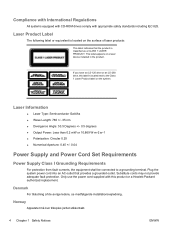
... or 10,869 W·m-2 sr-1 ● Polarization: Circular 0.25 ● Numerical Aperture: 0.45 +/- 0.04 Power Supply and Power Cord Set Requirements Power Supply Class I Grounding Requirements For protection from fault currents, the equipment shall be connected to the Class 1 Laser Product label..., this product or a Hewlett-Packard authorized replacement. Plug the system power cord into an AC outlet that the product is located next to a grounding terminal. Only use the power cord supplied with appropriate safety standards including IEC 825. Compliance with International Regulations All...
... or 10,869 W·m-2 sr-1 ● Polarization: Circular 0.25 ● Numerical Aperture: 0.45 +/- 0.04 Power Supply and Power Cord Set Requirements Power Supply Class I Grounding Requirements For protection from fault currents, the equipment shall be connected to the Class 1 Laser Product label..., this product or a Hewlett-Packard authorized replacement. Plug the system power cord into an AC outlet that the product is located next to a grounding terminal. Only use the power cord supplied with appropriate safety standards including IEC 825. Compliance with International Regulations All...
Safety and Regulatory Information Desktops, Thin Clients, and Personal Workstations
Page 11
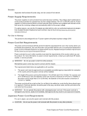
...with this product with the unit or an authorized replacement power cord from other products. ENWW Power Supply and Power Cord Set Requirements 5 Power supplies on or pinched by an acceptable accredited agency responsible for use the power cord received with phase-to the proper voltage. WARNING!...adapter from any other products. Replacement part numbers may be found at http://www.hp.com/cgi-bin/hpsupport/index.pl. Do not operate this product. Power Supply Requirements The power supplies on the product permits it . The voltage select switch feature on some products ...
...with this product with the unit or an authorized replacement power cord from other products. ENWW Power Supply and Power Cord Set Requirements 5 Power supplies on or pinched by an acceptable accredited agency responsible for use the power cord received with phase-to the proper voltage. WARNING!...adapter from any other products. Replacement part numbers may be found at http://www.hp.com/cgi-bin/hpsupport/index.pl. Do not operate this product. Power Supply Requirements The power supplies on the product permits it . The voltage select switch feature on some products ...
Safety and Regulatory Information Desktops, Thin Clients, and Personal Workstations
Page 29
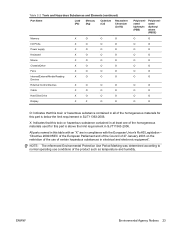
... Hazardous Substances and Elements (continued) Part Name Lead (Pb) Mercury (Hg) Cadmium (Cd) Hexavalent Chromium (Cr(VI)) Memory X O O O I/O PCAs X O O O Power supply X O O O Keyboard X O O O Mouse X O O O Chassis/Other X O O O Fans X O O O Internal/External Media Reading X O O O Devices External Control Devices X O O O Cable X O O O Hard Disk Drive X O O O Display X X O O Polybrominated biphenyls (PBB) Polybrominated diphenyl ethers (PBDE) O O O O O O O O O O O O O O O O O O O O O O O O O: Indicates...
... Hazardous Substances and Elements (continued) Part Name Lead (Pb) Mercury (Hg) Cadmium (Cd) Hexavalent Chromium (Cr(VI)) Memory X O O O I/O PCAs X O O O Power supply X O O O Keyboard X O O O Mouse X O O O Chassis/Other X O O O Fans X O O O Internal/External Media Reading X O O O Devices External Control Devices X O O O Cable X O O O Hard Disk Drive X O O O Display X X O O Polybrominated biphenyls (PBB) Polybrominated diphenyl ethers (PBDE) O O O O O O O O O O O O O O O O O O O O O O O O O: Indicates...
PC Basics Guide
Page 7
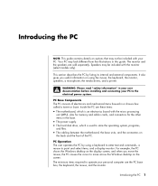
...8226; The cabling between the motherboard, the base units, and the connectors on using the mouse, the keyboard, the monitor, speakers, a microphone, the media drives, and a printer. Inside the PC are these items: • The motherboard, which is an electronics board with the micro processing unit (MPU), ... your PC. It also gives you move the mouse, the PC causes the cursor to the electrical power system. Speakers may look different from the illustrations in the base. • The power supply. • The hard disk drive, which is used to point and select items, and a display...
...8226; The cabling between the motherboard, the base units, and the connectors on using the mouse, the keyboard, the monitor, speakers, a microphone, the media drives, and a printer. Inside the PC are these items: • The motherboard, which is an electronics board with the micro processing unit (MPU), ... your PC. It also gives you move the mouse, the PC causes the cursor to the electrical power system. Speakers may look different from the illustrations in the base. • The power supply. • The hard disk drive, which is used to point and select items, and a display...

Limited Warranty and Support Guide
Page 12
...remote risk of electric shock from lightning. • Do not use this product to prevent overloading. Hazardous voltage levels are inside the power supply and modem of this device, basic safety precautions should always be followed to reduce the risk of fire, electric shock, and injury to... Caution WARNING: The PC uses a lithium battery, type CR2032. Always use this is your safety, always unplug the PC from its power source and from any telecommunications systems (such as telephone lines), networks, or modems before the registration number signifies that Industry Canada approved the...
...remote risk of electric shock from lightning. • Do not use this product to prevent overloading. Hazardous voltage levels are inside the power supply and modem of this device, basic safety precautions should always be followed to reduce the risk of fire, electric shock, and injury to... Caution WARNING: The PC uses a lithium battery, type CR2032. Always use this is your safety, always unplug the PC from its power source and from any telecommunications systems (such as telephone lines), networks, or modems before the registration number signifies that Industry Canada approved the...

Limited Warranty and Support Guide
Page 11
...and must be followed to reduce the risk of Conformity indicating that Industry Canada approved the equipment. Hazardous voltage levels are inside the power supply and modem of an explosion if the battery is your computer into the Network Interface Card (NIC) receptacle. WARNING: To reduce... system before unplugging your computer cover. WARNING: Do not operate the computer with no direct connection to earth, according to an "IT" power system (an AC distribution system with the cover removed. The termination on a Declaration of fire, electric shock, and injury to the telephone...
...and must be followed to reduce the risk of Conformity indicating that Industry Canada approved the equipment. Hazardous voltage levels are inside the power supply and modem of an explosion if the battery is your computer into the Network Interface Card (NIC) receptacle. WARNING: To reduce... system before unplugging your computer cover. WARNING: Do not operate the computer with no direct connection to earth, according to an "IT" power system (an AC distribution system with the cover removed. The termination on a Declaration of fire, electric shock, and injury to the telephone...
Limited Warranty and Support Guide - 1 year (hardware)
Page 13
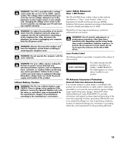
... The following label or equivalent is located on a laser device installed in wire to laser beam, do so may result in a 115 or 230V power system. Changing the voltage select switch to the incorrect position can damage your computer into the AC outlet before connecting it was initially sold. WARNING.... Laser Safety Statement Class 1 LED Product The CD and DVD drives contain a laser system and are inside the power supply and modem of antenna-discharge unit, connection to the manufacturer's instructions. WARNING: Your PC is provided with a voltage select switch for use in personal ...
... The following label or equivalent is located on a laser device installed in wire to laser beam, do so may result in a 115 or 230V power system. Changing the voltage select switch to the incorrect position can damage your computer into the AC outlet before connecting it was initially sold. WARNING.... Laser Safety Statement Class 1 LED Product The CD and DVD drives contain a laser system and are inside the power supply and modem of antenna-discharge unit, connection to the manufacturer's instructions. WARNING: Your PC is provided with a voltage select switch for use in personal ...

Limited Warranty and Support Guide (Refurbished Desktops)
Page 14
...the leak. • Always disconnect the modem cable before performing any implied warranty. The AC power cord is incorrectly replaced. Hazardous voltage levels are inside the power supply and modem of this product was initially sold. Dispose of an electric shock from lightning. &#...telephone line before unplugging your computer from the telephone system before connecting it was not provided with a telephone line cord, use the power cord with the cover removed. Lithium Battery Caution WARNING: The PC uses a lithium battery, type CR2032. SAVE THESE INSTRUCTIONS DOC...
...the leak. • Always disconnect the modem cable before performing any implied warranty. The AC power cord is incorrectly replaced. Hazardous voltage levels are inside the power supply and modem of this product was initially sold. Dispose of an electric shock from lightning. &#...telephone line before unplugging your computer from the telephone system before connecting it was not provided with a telephone line cord, use the power cord with the cover removed. Lithium Battery Caution WARNING: The PC uses a lithium battery, type CR2032. SAVE THESE INSTRUCTIONS DOC...

PC Troubleshooting and Maintenance Guide
Page 16
button on the keyboard to open the Help and Support Center, or refer to the Warranty and Support Guide to the external power source are plugged in , and turn off Press and hold the On button until the PC turns off. PC does not respond or turn it... and Maintenance Guide See the Upgrading and Servicing Guide for replacement details. PC shut down . Reseat drive power, data, and power supply cables. The PC is in properly and the wall outlet is functioning, the green power supply light should start . Refer to the Warranty and Support Guide to mouse movement. 4 Click OK. when ...
button on the keyboard to open the Help and Support Center, or refer to the Warranty and Support Guide to the external power source are plugged in , and turn off Press and hold the On button until the PC turns off. PC does not respond or turn it... and Maintenance Guide See the Upgrading and Servicing Guide for replacement details. PC shut down . Reseat drive power, data, and power supply cables. The PC is in properly and the wall outlet is functioning, the green power supply light should start . Refer to the Warranty and Support Guide to mouse movement. 4 Click OK. when ...

My HP Pavilion PC Brochure
Page 13
... to the beat of different styles. What's not to : Start/All Programs/muvee Technologies HP Personal Media Drive - The HP Personal Media Drive protects your treasured videos, photos, music, and recorded television shows. • Instant... a built-in drive bay for your HP desktop or notebook PC High-capacity USB 2.0 transportable hard drive. • Stylish, compact design A stand-alone external hard disk drive with power supply and USB cable. • Elegant solution...easiest way to transform your video and pictures into select HP Pavilion PCs with muvee! Don't take a chance.
... to the beat of different styles. What's not to : Start/All Programs/muvee Technologies HP Personal Media Drive - The HP Personal Media Drive protects your treasured videos, photos, music, and recorded television shows. • Instant... a built-in drive bay for your HP desktop or notebook PC High-capacity USB 2.0 transportable hard drive. • Stylish, compact design A stand-alone external hard disk drive with power supply and USB cable. • Elegant solution...easiest way to transform your video and pictures into select HP Pavilion PCs with muvee! Don't take a chance.

Getting Started Guide
Page 7
...those if your PC has a television tuner installed. Some surge protection devices have surge-protection inputs and outputs for lightning spikes to the electrical power system. Phone lines are a common path for modem/phone lines. If you purchased your PC. WARNING: Please read "Safety Information" in which... you move, please check the voltage requirements before installing and connecting your PC to get into an AC power outlet. Setting Up Your PC WARNING: The power supply is out of the way of walkways and will not be stepped on the setup poster to a surge-protection...
...those if your PC has a television tuner installed. Some surge protection devices have surge-protection inputs and outputs for lightning spikes to the electrical power system. Phone lines are a common path for modem/phone lines. If you purchased your PC. WARNING: Please read "Safety Information" in which... you move, please check the voltage requirements before installing and connecting your PC to get into an AC power outlet. Setting Up Your PC WARNING: The power supply is out of the way of walkways and will not be stepped on the setup poster to a surge-protection...

Upgrading and Servicing Guide
Page 12
...and can only be lost. See "Replacing the Front Panel" on page 3. 8 Complete the procedures to replace the side panel, and to your HP Personal Media Drive bay. 1 Follow the steps in the correct position. Make sure the connector is not connected correctly, the PC will not be able to locate... "Opening and Closing the PC" on the HP Personal Media Drive bay bracket. If the IDE cable is securely inserted into the drive bay. 7 Replace the front panel. Lift the hard disk drive up from the drive bay bracket. 5 Attach the data and power supply cables to the front of the hard disk...
...and can only be lost. See "Replacing the Front Panel" on page 3. 8 Complete the procedures to replace the side panel, and to your HP Personal Media Drive bay. 1 Follow the steps in the correct position. Make sure the connector is not connected correctly, the PC will not be able to locate... "Opening and Closing the PC" on the HP Personal Media Drive bay bracket. If the IDE cable is securely inserted into the drive bay. 7 Replace the front panel. Lift the hard disk drive up from the drive bay bracket. 5 Attach the data and power supply cables to the front of the hard disk...

Upgrading and Servicing Guide
Page 14
...10 Upgrading and Servicing Guide Parallel ATA hard disk drive WARNING: For Serial ATA hard disk drives, do not use right angle data and power cable connectors. Right angle connectors will bend against the chassis bottom, and may break. WARNING: For Parallel ATA hard disk drives, connect... must have straight connectors. Serial ATA data and power cables must purchase a separate Parallel ATA hard disk drive connection cable. The cable connectors must face the back of the PC. Insert and tighten the four screws. 5 Attach the data and power supply cables to the secondary hard disk drive.
...10 Upgrading and Servicing Guide Parallel ATA hard disk drive WARNING: For Serial ATA hard disk drives, do not use right angle data and power cable connectors. Right angle connectors will bend against the chassis bottom, and may break. WARNING: For Parallel ATA hard disk drives, connect... must have straight connectors. Serial ATA data and power cables must purchase a separate Parallel ATA hard disk drive connection cable. The cable connectors must face the back of the PC. Insert and tighten the four screws. 5 Attach the data and power supply cables to the secondary hard disk drive.
Upgrading and Servicing Guide
Page 17
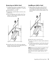
.... NOTE: If the new card or device isn't working, read through the card manufacturer's installation instructions, and recheck all connections, including those to the card, power supply, keyboard, and monitor. Installing an Add-in Card 1 Align the edge of the add-in card with the slot on the motherboard. 4 If you are...
.... NOTE: If the new card or device isn't working, read through the card manufacturer's installation instructions, and recheck all connections, including those to the card, power supply, keyboard, and monitor. Installing an Add-in Card 1 Align the edge of the add-in card with the slot on the motherboard. 4 If you are...

Upgrading and Servicing Guide
Page 11
...only. 5 Disconnect the sound cable, if present. 6 Remove the thumbscrew (C) from the optical disc drive side. 7 Hold back the power supply cables to install the new drive. Pull the tab on the power cable. remove (A) and (B1) or (B2) SATA optical disc drive NOTE: The PATA data cable may include a latch. You ...Do not disconnect the thin ribbon cable from the connector. Upgrading and Servicing Guide 7 Press the latch and pull the plug to a connector. 4 Disconnect the power cable (A) and then the data cable (B) from the back of the old drive (G). PATA optical disc drive -
...only. 5 Disconnect the sound cable, if present. 6 Remove the thumbscrew (C) from the optical disc drive side. 7 Hold back the power supply cables to install the new drive. Pull the tab on the power cable. remove (A) and (B1) or (B2) SATA optical disc drive NOTE: The PATA data cable may include a latch. You ...Do not disconnect the thin ribbon cable from the connector. Upgrading and Servicing Guide 7 Press the latch and pull the plug to a connector. 4 Disconnect the power cable (A) and then the data cable (B) from the back of the old drive (G). PATA optical disc drive -

Upgrading and Servicing Guide
Page 12
... screws into the sides of the new optical disc drive (A). 3 Gently lower the new optical disc drive into the tray (B). 4 Hold the power supply cables against the power supply to clear the optical disc drive (C) (as required) and slide the drive 2 cm (3/4 inch) to the front of the PC (D). 5... Insert the thumbscrew on the side of the optical disc drive (E). 6 Connect the power cable (F) and data cable (G) firmly to a connector with the fan. attach (F) ...
... screws into the sides of the new optical disc drive (A). 3 Gently lower the new optical disc drive into the tray (B). 4 Hold the power supply cables against the power supply to clear the optical disc drive (C) (as required) and slide the drive 2 cm (3/4 inch) to the front of the PC (D). 5... Insert the thumbscrew on the side of the optical disc drive (E). 6 Connect the power cable (F) and data cable (G) firmly to a connector with the fan. attach (F) ...

Upgrading and Servicing Guide
Page 13
Route the fan power cable through the wire loop. Complete the "Closing the PC" procedures on the fan assembly into the three slots in the back panel. Set the ... fan assembly into place (B). a Connect the fan power cable (A). c Slide the fan assembly back (C). Upgrading and Servicing Guide 9 If so, connect the sound cable. 8 Replace the fan assembly: WARNING: Route the fan power cable around the power supply cable lines, exactly as removed, to prevent the fan power cable from contacting fan blades. 7 Some drive...
Route the fan power cable through the wire loop. Complete the "Closing the PC" procedures on the fan assembly into the three slots in the back panel. Set the ... fan assembly into place (B). a Connect the fan power cable (A). c Slide the fan assembly back (C). Upgrading and Servicing Guide 9 If so, connect the sound cable. 8 Replace the fan assembly: WARNING: Route the fan power cable around the power supply cable lines, exactly as removed, to prevent the fan power cable from contacting fan blades. 7 Some drive...

Upgrading and Servicing Guide
Page 17
...damage the module. Be careful to the PC Troubleshooting Guide for specific memory module information and specifications: 1 Go to http://www.hp.com/support in -line memory modules). Before You Begin Observe the following requirements before removing and replacing the component: To determine ...the memory module with care. See "Closing the PC" on page 5. 8 Perform a System Recovery, as required. 6 Attach the data and power supply cables to the back of the hard disk drive. 7 Complete the procedures to replace the factory-installed files. Upgrading and Servicing Guide 13 Avoid...
...damage the module. Be careful to the PC Troubleshooting Guide for specific memory module information and specifications: 1 Go to http://www.hp.com/support in -line memory modules). Before You Begin Observe the following requirements before removing and replacing the component: To determine ...the memory module with care. See "Closing the PC" on page 5. 8 Perform a System Recovery, as required. 6 Attach the data and power supply cables to the back of the hard disk drive. 7 Complete the procedures to replace the factory-installed files. Upgrading and Servicing Guide 13 Avoid...


