

HP DTC Cabling and Racking Guide
Page 20
... rail kit. 1 Mount the side brackets on the front of the system rack, with brackets attached for mounting in an HP cabinet, you need to test the DTC or interpret faults. The system rack front panel fits onto the "snaps" attached to these brackets. Each DTC 72MX occupies three EIA units... in a rack. 4 Racking a DTC 72MX with a system rack front panel Racking a DTC 72MX with a system rack front panel The DTC 72MX can see the diagnostic LED displays on the DTC (if they are not already attached). 2 Attach the front-panel snaps to the brackets. 14
... rail kit. 1 Mount the side brackets on the front of the system rack, with brackets attached for mounting in an HP cabinet, you need to test the DTC or interpret faults. The system rack front panel fits onto the "snaps" attached to these brackets. Each DTC 72MX occupies three EIA units... in a rack. 4 Racking a DTC 72MX with a system rack front panel Racking a DTC 72MX with a system rack front panel The DTC 72MX can see the diagnostic LED displays on the DTC (if they are not already attached). 2 Attach the front-panel snaps to the brackets. 14
rp24xx A180 User Manual
Page 6
... Configuration 59 Overview 59 3. A-Class System Service A-Class System Repair 62 Overview 62 A-Class Server Fault Condition Recognition 63 Overview 63 Review Front Panel Status LEDs 63 Review Console Messages 64 A-Class Server Trouble Shooting 65 Overview 65 A-Class Server Selftest Failures/Warnings... 66 Troubleshooting with Light-Emitting Diode (LED) Interpretation 66 Firmware Warning Messages 72 Chassis Code Summary 73 Troubleshooting the ASCII Console 76 Troubleshooting the Secure Web ...
... Configuration 59 Overview 59 3. A-Class System Service A-Class System Repair 62 Overview 62 A-Class Server Fault Condition Recognition 63 Overview 63 Review Front Panel Status LEDs 63 Review Console Messages 64 A-Class Server Trouble Shooting 65 Overview 65 A-Class Server Selftest Failures/Warnings... 66 Troubleshooting with Light-Emitting Diode (LED) Interpretation 66 Firmware Warning Messages 72 Chassis Code Summary 73 Troubleshooting the ASCII Console 76 Troubleshooting the Secure Web ...
rp24xx A180 User Manual
Page 62
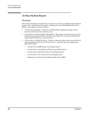
... LED patterns displayed during normal operation and when fault conditions occur. • "A-Class Server Fault Condition Recognition". "A-Class Server RAM Removal and Replacement" - "A-Class Server I/O Card Removal and Replacement" - This section is divided into two levels: tasks that can be performed by qualified HP ...Parts for the A-Class Server", and removing and replacing the FRUs listed below describe the procedures you will use to identify fault conditions in your server, troubleshoot the system, exchange the server Field Replaceable Units (FRUs), and configure system hardware: •...
... LED patterns displayed during normal operation and when fault conditions occur. • "A-Class Server Fault Condition Recognition". "A-Class Server RAM Removal and Replacement" - "A-Class Server I/O Card Removal and Replacement" - This section is divided into two levels: tasks that can be performed by qualified HP ...Parts for the A-Class Server", and removing and replacing the FRUs listed below describe the procedures you will use to identify fault conditions in your server, troubleshoot the system, exchange the server Field Replaceable Units (FRUs), and configure system hardware: •...

rp24xx A180 User Manual
Page 63
... Blink Pattern Off Indication Normal Operation (HP-UX running) 2nd Level Cache SIMM fault On (Steady) Off Memory SIMM fault On (Steady On (Steady) I/O Subsystem or I/O Board fault Off On (Steady) System board fault, HPMC or Unknown fault Blinking Blinking opposite of Heartbeat LED Off On (Steady) I/O HPMC fault Blinking opposite of fault conditions are determined by reviewing Front...
... Blink Pattern Off Indication Normal Operation (HP-UX running) 2nd Level Cache SIMM fault On (Steady) Off Memory SIMM fault On (Steady On (Steady) I/O Subsystem or I/O Board fault Off On (Steady) System board fault, HPMC or Unknown fault Blinking Blinking opposite of Heartbeat LED Off On (Steady) I/O HPMC fault Blinking opposite of fault conditions are determined by reviewing Front...

rp24xx A180 User Manual
Page 65
...recognize repeatable hardware failures that prevent completion of the server selftest, or hardware failures that will not allow the HP-UX operating system to the suspect peripheral's documentation for troubleshooting assistance. Do not use this information to troubleshoot...HPMC), or Unknown Fault. - Second Level Cache Memory Module Fault. - Random Access Memory (RAM) Module Fault. - Use the troubleshooting data and procedures in the subsections listed below: • A-Class Server Selftest Failures/Warnings • Troubleshooting with Light-Emitting Diode (LED) Interpretation - ...
...recognize repeatable hardware failures that prevent completion of the server selftest, or hardware failures that will not allow the HP-UX operating system to the suspect peripheral's documentation for troubleshooting assistance. Do not use this information to troubleshoot...HPMC), or Unknown Fault. - Second Level Cache Memory Module Fault. - Random Access Memory (RAM) Module Fault. - Use the troubleshooting data and procedures in the subsections listed below: • A-Class Server Selftest Failures/Warnings • Troubleshooting with Light-Emitting Diode (LED) Interpretation - ...

rp24xx A180 User Manual
Page 66
...repaired by replacing the A-Class Exchange Base Unit (EBU). Troubleshooting with Light-Emitting Diode (LED) Interpretation The LED icons shown above are physically located on the right-hand side of the fault. The left-most icon is usually in the A-Class server power supply. Successful Power-...to identify which takes approximately 2 seconds. Refer to the Chassis Code Summary section. When selftest is on. When power is inaccessible. LED icon states will appear as dictated by chassis code analysis, refer to the Replacing an A-Class Server Exchange Base Unit (EBU) section....
...repaired by replacing the A-Class Exchange Base Unit (EBU). Troubleshooting with Light-Emitting Diode (LED) Interpretation The LED icons shown above are physically located on the right-hand side of the fault. The left-most icon is usually in the A-Class server power supply. Successful Power-...to identify which takes approximately 2 seconds. Refer to the Chassis Code Summary section. When selftest is on. When power is inaccessible. LED icon states will appear as dictated by chassis code analysis, refer to the Replacing an A-Class Server Exchange Base Unit (EBU) section....
rp24xx A180 User Manual
Page 67
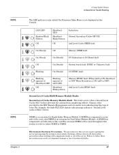
... Blink Pattern Off Indication Normal Operation (Under HP-UX) 2nd Level Cache SIMM fault On (Steady) Off Memory SIMM fault On (Steady On (Steady) I/O Subsystem or I/O Board fault Off On (Steady) System board fault, HPMC or Unknown fault Blinking On (Steady) I/O HPMC fault Blinking opposite of Heartbeat LED Off Blinking opposite of the card, only.DIMM is an...
... Blink Pattern Off Indication Normal Operation (Under HP-UX) 2nd Level Cache SIMM fault On (Steady) Off Memory SIMM fault On (Steady On (Steady) I/O Subsystem or I/O Board fault Off On (Steady) System board fault, HPMC or Unknown fault Blinking On (Steady) I/O HPMC fault Blinking opposite of Heartbeat LED Off Blinking opposite of the card, only.DIMM is an...

rp24xx A180 User Manual
Page 68
...accumulated electrostatic charge is required. If the fault does not recur, the problem was caused by unscrewing the knurled captive screws on an ESD mat. Single SLC SIMM Troubleshooting. Step 2. Step 3. Power up and observe front panel LEDs. If the fault recurs, the problem is with the system... board. If fault does not recur, the problem is with the SLC SIMMs. Either replace both SLC SIMMs and place ...
...accumulated electrostatic charge is required. If the fault does not recur, the problem was caused by unscrewing the knurled captive screws on an ESD mat. Single SLC SIMM Troubleshooting. Step 2. Step 3. Power up and observe front panel LEDs. If the fault recurs, the problem is with the system... board. If fault does not recur, the problem is with the SLC SIMMs. Either replace both SLC SIMMs and place ...

rp24xx A180 User Manual
Page 69
... RAM Module Troubleshooting. Step 4. Either replace both sides of SIMMs. Power up the server and observe the front panel LEDs. Single RAM Module Troubleshooting. This fault occurs when a RAM failure prevents the system from the cabinet before proceeding. • Remove the top of the server by the HSC ...the original RAM SIMMs in and power up the server and observe the front panel LEDs. Step 2. Remove all electrostatic precautions when working with one of the RAM SIMM fault. Plug in slot B. Step 3. If fault does not recur, the SIMMs installed in slot 0a and 0b are installed in ...
... RAM Module Troubleshooting. Step 4. Either replace both sides of SIMMs. Power up the server and observe the front panel LEDs. Single RAM Module Troubleshooting. This fault occurs when a RAM failure prevents the system from the cabinet before proceeding. • Remove the top of the server by the HSC ...the original RAM SIMMs in and power up the server and observe the front panel LEDs. Step 2. Remove all electrostatic precautions when working with one of the RAM SIMM fault. Plug in slot B. Step 3. If fault does not recur, the SIMMs installed in slot 0a and 0b are installed in ...

rp24xx A180 User Manual
Page 70
...require opening the server and exposing the system to step 8. Power up the server, and observe the front panel LEDs. 70 Chapter 3 If the fault does not recur, the problem is with the other original RAM SIMM. Chassis codes provided by unscrewing the knurled captive... system and resume normal operations. The procedures in slot B. Document the I/O configuration (write down which type of I /O Board Faults using the front panel LEDs, follow these precautions may result in slot B with the RAM SIMM that any accumulated electrostatic charge is not presently installed. If ...
...require opening the server and exposing the system to step 8. Power up the server, and observe the front panel LEDs. 70 Chapter 3 If the fault does not recur, the problem is with the other original RAM SIMM. Chassis codes provided by unscrewing the knurled captive... system and resume normal operations. The procedures in slot B. Document the I/O configuration (write down which type of I /O Board Faults using the front panel LEDs, follow these precautions may result in slot B with the RAM SIMM that any accumulated electrostatic charge is not presently installed. If ...

rp24xx A180 User Manual
Page 71
...of error. Refer to the Random Access Memory (RAM) Module Fault. Refer to an I /O card, power up the server, and observe the front panel LEDs. For assistance with the system board. Chapter 3 71 To troubleshoot an I/O HPMC fault, refer to a RAM failure, prevents the system from completing ...Check the timestamp on the server and observe both the front panel LEDs and the console. This fault occurs when the system board has an irrecoverable fault or an HPMC prevents the system from completing selftest. If the fault does not recur, install the second I /O failure, prevents the ...
...of error. Refer to the Random Access Memory (RAM) Module Fault. Refer to an I /O card, power up the server, and observe the front panel LEDs. For assistance with the system board. Chapter 3 71 To troubleshoot an I/O HPMC fault, refer to a RAM failure, prevents the system from completing ...Check the timestamp on the server and observe both the front panel LEDs and the console. This fault occurs when the system board has an irrecoverable fault or an HPMC prevents the system from completing selftest. If the fault does not recur, install the second I /O failure, prevents the ...

rp24xx A180 User Manual
Page 78
...to as the Administrator and check the DATACOM configuration. Type the IP address of the screen and is updated until selftest is the green POWER LED). When the Web console page appears, log in one of two ways: If an HSC Remote Management card is installed, the output appears at...is complete and the firmware Main Menu screen appears. Chapter 3 Log in to Chapter 2. 2. Click on the rear of a web console fault. The A-Class server front panel LEDs do not indicate Web console failures. Resetting the Web console will display selftest data output in . There are no output to show the ...
...to as the Administrator and check the DATACOM configuration. Type the IP address of the screen and is updated until selftest is the green POWER LED). When the Web console page appears, log in one of two ways: If an HSC Remote Management card is installed, the output appears at...is complete and the firmware Main Menu screen appears. Chapter 3 Log in to Chapter 2. 2. Click on the rear of a web console fault. The A-Class server front panel LEDs do not indicate Web console failures. Resetting the Web console will display selftest data output in . There are no output to show the ...

rp24xx A180 User Manual
Page 79
...Operating System software. The example provided below starts with entry of the server. If the ASCII console works, but do not have an individual fault LED to show operational status. ENTRY_INIT Status = -10 Chapter 3 79 The user whose name is with IPL (Y, N, or Cancel)? > y... Booting... Though embedded disks are installed internally, the server's front panel LEDs do not reflect disk status and therefore will be taken, not given. Refer to the Replacing an A-Class Server Exchange Base Unit (EBU) section....
...Operating System software. The example provided below starts with entry of the server. If the ASCII console works, but do not have an individual fault LED to show operational status. ENTRY_INIT Status = -10 Chapter 3 79 The user whose name is with IPL (Y, N, or Cancel)? > y... Booting... Though embedded disks are installed internally, the server's front panel LEDs do not reflect disk status and therefore will be taken, not given. Refer to the Replacing an A-Class Server Exchange Base Unit (EBU) section....


