End User License Agreement
Page 2
... may no longer use the original Software Product that the right to the original Software Product provided by HP or its affiliates may not reverse engineer, decompile, or disassemble the Software Product, except and only to United States copyright, trade secret, and trademark law, as ...well as eligible for commercial timesharing or bureau use of Authenticity. You agree that HP and its suppliers and are owned by HP unless HP provides other form, ...
... may no longer use the original Software Product that the right to the original Software Product provided by HP or its affiliates may not reverse engineer, decompile, or disassemble the Software Product, except and only to United States copyright, trade secret, and trademark law, as ...well as eligible for commercial timesharing or bureau use of Authenticity. You agree that HP and its suppliers and are owned by HP unless HP provides other form, ...
Reference Guide
Page 2
.... Reference Guide Second Edition (March 2003) Part Number: 311074-002 ii Reference Guide registered trademarks and Celeron™ and SpeedStep™ are U.S. Reverse engineering or disassembly is intended for a particular purpose. shall not be copyrighted by Macrovision Corporation. All rights reserved. registered trademarks of merchantability and fitness for home and other...
.... Reference Guide Second Edition (March 2003) Part Number: 311074-002 ii Reference Guide registered trademarks and Celeron™ and SpeedStep™ are U.S. Reverse engineering or disassembly is intended for a particular purpose. shall not be copyrighted by Macrovision Corporation. All rights reserved. registered trademarks of merchantability and fitness for home and other...
Reference Guide
Page 107
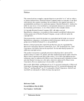
... and DVD drives used with soap and water. These devices are certified as a Class 1 laser devices according to touch the battery contacts. • Do not disassemble the battery. If it contacts the eye, flush the eye with water for 15 minutes and seek medical attention. • Do not expose the battery...
... and DVD drives used with soap and water. These devices are certified as a Class 1 laser devices according to touch the battery contacts. • Do not disassemble the battery. If it contacts the eye, flush the eye with water for 15 minutes and seek medical attention. • Do not expose the battery...
Maintenance and Service Guide
Page 3
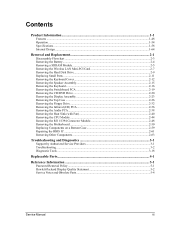
Contents Introduction...vii Product Information...1-1 Features ...1-8 Operation...1-14 Specifications ...1-18 Internal Design...1-24 Removal and Replacement 2-1 Disassembly Flowchart ...2-3 Removing the Battery ...2-4 Removing an SDRAM Module...2-5 Removing the Wireless LAN Mini PCI Card 2-7 Removing the Hard Disk Drive...2-9 Recovering the Factory Software...2-11 ...
Contents Introduction...vii Product Information...1-1 Features ...1-8 Operation...1-14 Specifications ...1-18 Internal Design...1-24 Removal and Replacement 2-1 Disassembly Flowchart ...2-3 Removing the Battery ...2-4 Removing an SDRAM Module...2-5 Removing the Wireless LAN Mini PCI Card 2-7 Removing the Hard Disk Drive...2-9 Recovering the Factory Software...2-11 ...
Maintenance and Service Guide
Page 4
...Figure 1-5. Removing an SDRAM Module 2-6 Figure 2-5. AMD CPU Module Installation 2-39 Figure 2-32 Removing the CPU Module 2-39 Figure 2-33. Disassembly Flow...2-3 Figure 2-2. Removing the Hard Disk Drive 2-9 Figure 2-8. Removing an SDRAM Module 2-5 Figure 2-4. Removing the Mini PCI Card 2-8 ...Figure 2-9. Removing the Floppy Drive 2-33 Figure 2-23. Intel CPU Module Removal 2-45 Figure 2-29. Figures Figure 1-1. Resetting the Notebook ...1-17 Figure 1-8. Removing the Switchboard PCA 2-19 Figure 2-15. Removing the Top Case Screws 2-30 Figure 2-21. Removing the...
...Figure 1-5. Removing an SDRAM Module 2-6 Figure 2-5. AMD CPU Module Installation 2-39 Figure 2-32 Removing the CPU Module 2-39 Figure 2-33. Disassembly Flow...2-3 Figure 2-2. Removing the Hard Disk Drive 2-9 Figure 2-8. Removing an SDRAM Module 2-5 Figure 2-4. Removing the Mini PCI Card 2-8 ...Figure 2-9. Removing the Floppy Drive 2-33 Figure 2-23. Intel CPU Module Removal 2-45 Figure 2-29. Figures Figure 1-1. Resetting the Notebook ...1-17 Figure 1-8. Removing the Switchboard PCA 2-19 Figure 2-15. Removing the Top Case Screws 2-30 Figure 2-21. Removing the...
Maintenance and Service Guide
Page 33
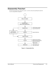
Disassembly Flowchart The following diagram shows the general "path" you will use when disassembling the notebook to access any particular component. Disassembly Flow Service Manual Removal and Replacement 2-3 Figure 2-1.
Disassembly Flowchart The following diagram shows the general "path" you will use when disassembling the notebook to access any particular component. Disassembly Flow Service Manual Removal and Replacement 2-3 Figure 2-1.
Service Manual
Page 3
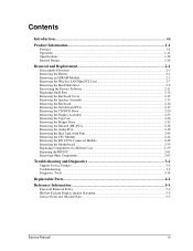
Contents Product Information...1-1 Features ...1-48 Operation ...1-54 Specifications ...1-58 Internal Design ...1-64 Removal and Replacement 2-1 Disassembly Flowchart ...2-3 Removing the Battery...2-4 Removing a SDRAM Module...2-5 Removing the Wireless LAN Mini-PCI Card 2-7 Removing the Hard Disk Drive...2-9 Replacing Small Parts ...2-11 Removing the ...
Contents Product Information...1-1 Features ...1-48 Operation ...1-54 Specifications ...1-58 Internal Design ...1-64 Removal and Replacement 2-1 Disassembly Flowchart ...2-3 Removing the Battery...2-4 Removing a SDRAM Module...2-5 Removing the Wireless LAN Mini-PCI Card 2-7 Removing the Hard Disk Drive...2-9 Replacing Small Parts ...2-11 Removing the ...
Service Manual
Page 4
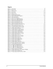
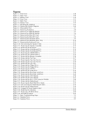
Figures Figure 1-1. Disassembly Flow ...2-3 Figure 2-2. Removing the Keyboard Cover 2-13 Figure 2-10. Removing the Top Case Screws 2-29 Figure 2-20. Removing the Heat Sink (with Fan 2-40 Figure 2-... 2-38. Bottom View ...1-53 Figure 1-7. Removing the Motherboard 2-51 Figure 2-32. Example of Serial Number Label 2-59 Figure 2-36. Basic Troubleshooting Steps 3-2 Figure 4-1. Resetting the Notebook 1-57 Figure 1-8. Removing the Hard Disk Drive Tray 2-10 Figure 2-9. Removing the Display Assembly 2-24 Figure 2-18. Removing the Floppy Drive 2-33 Figure 2-23. Removing...
Figures Figure 1-1. Disassembly Flow ...2-3 Figure 2-2. Removing the Keyboard Cover 2-13 Figure 2-10. Removing the Top Case Screws 2-29 Figure 2-20. Removing the Heat Sink (with Fan 2-40 Figure 2-... 2-38. Bottom View ...1-53 Figure 1-7. Removing the Motherboard 2-51 Figure 2-32. Example of Serial Number Label 2-59 Figure 2-36. Basic Troubleshooting Steps 3-2 Figure 4-1. Resetting the Notebook 1-57 Figure 1-8. Removing the Hard Disk Drive Tray 2-10 Figure 2-9. Removing the Display Assembly 2-24 Figure 2-18. Removing the Floppy Drive 2-33 Figure 2-23. Removing...
Service Manual
Page 74
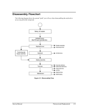
Figure 2-1. Disassembly Flow Service Manual Removal and Replacement 2-3 Disassembly Flowchart The following diagram shows the general "path" you will use when disassembling the notebook to access any particular component.
Figure 2-1. Disassembly Flow Service Manual Removal and Replacement 2-3 Disassembly Flowchart The following diagram shows the general "path" you will use when disassembling the notebook to access any particular component.


