
Hardware Reference Guide - HP rp3000
Page 32
... 10,000 ft 3048 m Nonoperating 30,000 ft 9144 m NOTE: Operating temperature is 10° C/Hr. no direct sustained sunlight. The active power factor corrected power supply also has the added benefit of change is derated 1.0° C per 300 m (1000 ft) to 3000 m (10,000 ft) above sea...240 VAC 100-240 VAC Rated Line Frequency 50-60 Hz 50-60 Hz Power Output 150 W 150 W Rated Input Current (maximum)1 3A @ 90 VAC 1.5A @ 180 VAC 1 This system utilizes an active power factor corrected power supply. Maximum rate of not requiring an input voltage range select switch. 26 ...
... 10,000 ft 3048 m Nonoperating 30,000 ft 9144 m NOTE: Operating temperature is 10° C/Hr. no direct sustained sunlight. The active power factor corrected power supply also has the added benefit of change is derated 1.0° C per 300 m (1000 ft) to 3000 m (10,000 ft) above sea...240 VAC 100-240 VAC Rated Line Frequency 50-60 Hz 50-60 Hz Power Output 150 W 150 W Rated Input Current (maximum)1 3A @ 90 VAC 1.5A @ 180 VAC 1 This system utilizes an active power factor corrected power supply. Maximum rate of not requiring an input voltage range select switch. 26 ...

Hardware Reference Guide - HP rp3000
Page 56
...HP Business PC Security Lock 44 padlock 44 sliding drive door 4 M memory installing 8 populating sockets 9 specifications 8 modem 3 monitor connector 3 mouse connector 3 N network connector 3 O optical drive cleaning 49 defined 2 installing 17 precautions 49 removing 17 P PCI card 12 PCI Express card 12 power supply 26 powered... serial ports configuring 33 expansion card jumpers 33 locations 31 removing caps 32 system board jumpers 33 product ID location 4 R rear panel components 3 removing battery...
...HP Business PC Security Lock 44 padlock 44 sliding drive door 4 M memory installing 8 populating sockets 9 specifications 8 modem 3 monitor connector 3 mouse connector 3 N network connector 3 O optical drive cleaning 49 defined 2 installing 17 precautions 49 removing 17 P PCI card 12 PCI Express card 12 power supply 26 powered... serial ports configuring 33 expansion card jumpers 33 locations 31 removing caps 32 system board jumpers 33 product ID location 4 R rear panel components 3 removing battery...

Illustrated Parts & Service Map: HP rp3000 Point of Sale
Page 1
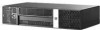
...USB 2.0 (6), USB+POWER (2)(some models), RS232 individually configurable to change 506600-002 page 1 S. Illustrated Parts & Service Map HP rp3000 Point of xxx947xxxx or ...System Unit 1 Power supply, 150W 2 5.25-inch bezel blank 3 Front bezel assembly, includes keys * Chassis assembly rp3000...Powered serial card 3 Modem, LSI MDC, includes internal RJ-11 cable 4 PCI riser card 5 PCIe x1 riser card assembly * ReadyBoost module kit. 1 GB System boards with thermal grease, alcohol pad, and CPU socket cover * System board, includes processor; for use in models with serial numbers of Sale...
...USB 2.0 (6), USB+POWER (2)(some models), RS232 individually configurable to change 506600-002 page 1 S. Illustrated Parts & Service Map HP rp3000 Point of xxx947xxxx or ...System Unit 1 Power supply, 150W 2 5.25-inch bezel blank 3 Front bezel assembly, includes keys * Chassis assembly rp3000...Powered serial card 3 Modem, LSI MDC, includes internal RJ-11 cable 4 PCI riser card 5 PCIe x1 riser card assembly * ReadyBoost module kit. 1 GB System boards with thermal grease, alcohol pad, and CPU socket cover * System board, includes processor; for use in models with serial numbers of Sale...

Illustrated Parts & Service Map: HP rp3000 Point of Sale
Page 2
...System does not power on State/Message Computer on Suspend to RAM mode Processor thermal protection activated Power failure (power supply overload) Pre-video memory error Pre-video graphics error System... second, fol- Expansion board option ROM checksum 1. Check connector for proper seating, type, and HP compatibility. 3. lowed by a 2 second pause 4 4 blinks, once per second, fol- Clear...to isolate faulty DIMM. 4. rp3000 Illustrated Parts & Service Map 506600-002 page 2 System ROM checksum error. 2. Clear CMOS memory. 2. Replace system board. 301-, 304-Keyboard ...
...System does not power on State/Message Computer on Suspend to RAM mode Processor thermal protection activated Power failure (power supply overload) Pre-video memory error Pre-video graphics error System... second, fol- Expansion board option ROM checksum 1. Check connector for proper seating, type, and HP compatibility. 3. lowed by a 2 second pause 4 4 blinks, once per second, fol- Clear...to isolate faulty DIMM. 4. rp3000 Illustrated Parts & Service Map 506600-002 page 2 System ROM checksum error. 2. Clear CMOS memory. 2. Replace system board. 301-, 304-Keyboard ...

Quick Setup and Getting Started Guide
Page 15
...-Provides definitions and "how to" instructions for troubleshooting this series of the publications listed are also available at http://www.hp.com/support. includes information about diagnostic codes, as well as instructions for upgrading this computer and scenarios for resolving possible ... should you connect the computer and peripheral devices and set up factoryprovided software; To access HP user guides on using this guide. includes information on RTC batteries, memory, and power supply. ● Computer Setup (F10) Utility Guide-Provides instructions on the hard drive: ▲...
...-Provides definitions and "how to" instructions for troubleshooting this series of the publications listed are also available at http://www.hp.com/support. includes information about diagnostic codes, as well as instructions for upgrading this computer and scenarios for resolving possible ... should you connect the computer and peripheral devices and set up factoryprovided software; To access HP user guides on using this guide. includes information on RTC batteries, memory, and power supply. ● Computer Setup (F10) Utility Guide-Provides instructions on the hard drive: ▲...

Service Reference Guide: HP rp3000 Point of Sale
Page 6
...SATA Power Cable ...24 PATA Device Information ...25 ATA SMART Drives ...25 Hard Drive Capacities ...25 5 Identifying the Chassis, Routine Care, and Disassembly Preparation Chassis Designations ...26 rp3000 ...Keyboard ...30 Cleaning the Monitor ...31 Cleaning the Mouse ...31 Service Considerations ...31 Power Supply Fan ...31 Tools and Software Requirements 31 Screws ...32 Cables and Connectors ...32... Preparation for Disassembly ...34 External Security Devices ...35 Cable Lock ...35 Padlock ...36 HP Business PC Security Lock 36 Computer Cover ...38 Bezel Blank ...39 Cable Management ...40...
...SATA Power Cable ...24 PATA Device Information ...25 ATA SMART Drives ...25 Hard Drive Capacities ...25 5 Identifying the Chassis, Routine Care, and Disassembly Preparation Chassis Designations ...26 rp3000 ...Keyboard ...30 Cleaning the Monitor ...31 Cleaning the Mouse ...31 Service Considerations ...31 Power Supply Fan ...31 Tools and Software Requirements 31 Screws ...32 Cables and Connectors ...32... Preparation for Disassembly ...34 External Security Devices ...35 Cable Lock ...35 Padlock ...36 HP Business PC Security Lock 36 Computer Cover ...38 Bezel Blank ...39 Cable Management ...40...

Service Reference Guide: HP rp3000 Point of Sale
Page 7
... Drives 60 Optical Drive ...62 Primary 3.5-inch Internal Hard Drive 64 Chassis Fan ...67 Power Switch/LED Assembly ...67 Modem (some models) ...68 Optical Drive Sensor ...69 Power Supply ...70 System Board ...71 Battery ...73 Appendix A Connector Pin Assignments Keyboard ...75 Mouse ...75 Ethernet... RJ-45 ...76 RJ-11 ...76 Serial Interface, Powered and Non-Powered 76 USB ...77 Powered USB ...77 Line-in Audio ...77 Line-...
... Drives 60 Optical Drive ...62 Primary 3.5-inch Internal Hard Drive 64 Chassis Fan ...67 Power Switch/LED Assembly ...67 Modem (some models) ...68 Optical Drive Sensor ...69 Power Supply ...70 System Board ...71 Battery ...73 Appendix A Connector Pin Assignments Keyboard ...75 Mouse ...75 Ethernet... RJ-45 ...76 RJ-11 ...76 Serial Interface, Powered and Non-Powered 76 USB ...77 Powered USB ...77 Line-in Audio ...77 Line-...

Service Reference Guide: HP rp3000 Point of Sale
Page 25
... internal speaker and PCI bus information. The Diagnosis feature of general information about all categories of select power supply models. The Smart Array Drive Diagnosis supports SCSI, serial Advanced Technology HP Insight Diagnostics 17 Architecture-Provides system BIOS and PCI device information. Overview-Gives you can select the Summary view to see limited configuration...
... internal speaker and PCI bus information. The Diagnosis feature of general information about all categories of select power supply models. The Smart Array Drive Diagnosis supports SCSI, serial Advanced Technology HP Insight Diagnostics 17 Architecture-Provides system BIOS and PCI device information. Overview-Gives you can select the Summary view to see limited configuration...

Service Reference Guide: HP rp3000 Point of Sale
Page 39
...of the considerations that the power to remove any debris from the housing. Use tweezers to the computer is a variable speed fan based on the temperature of the computer. The system fan is turned off when...page 30. Tools and Software Requirements To service the computer, you need the following: ● Torx T-15 screwdriver (HP screwdriver with bits, PN 161946-001) ● Torx T-15 screwdriver with a clean, dry cloth before reassembly. &#... confined areas. Pull out any fibers or dirt in the power supply. Power Supply Fan The power supply fan is available through many electronic...
...of the considerations that the power to remove any debris from the housing. Use tweezers to the computer is a variable speed fan based on the temperature of the computer. The system fan is turned off when...page 30. Tools and Software Requirements To service the computer, you need the following: ● Torx T-15 screwdriver (HP screwdriver with bits, PN 161946-001) ● Torx T-15 screwdriver with a clean, dry cloth before reassembly. &#... confined areas. Pull out any fibers or dirt in the power supply. Power Supply Fan The power supply fan is available through many electronic...

Service Reference Guide: HP rp3000 Point of Sale
Page 48
...A sharp bend can break the internal wires. ● Never bend a SATA data cable tighter than a 30 mm (1.18 in a failed power supply. Figure 6-9 System Board Power Supply Connector 40 Chapter 6 Removal and Replacement Procedures Printed circuit cards like these steps: 1. CAUTION: Always pull the connector - Grasp the cable end... to lay properly by themselves. Squeeze on the system board, always follow these are not designed to take excessive pressure on them. ● Keep cables clear of movable or rotating parts like the power supply and drive cage to prevent them from the connector...
...A sharp bend can break the internal wires. ● Never bend a SATA data cable tighter than a 30 mm (1.18 in a failed power supply. Figure 6-9 System Board Power Supply Connector 40 Chapter 6 Removal and Replacement Procedures Printed circuit cards like these steps: 1. CAUTION: Always pull the connector - Grasp the cable end... to lay properly by themselves. Squeeze on the system board, always follow these are not designed to take excessive pressure on them. ● Keep cables clear of movable or rotating parts like the power supply and drive cage to prevent them from the connector...

Service Reference Guide: HP rp3000 Point of Sale
Page 78
Voltage is always present on the system board when the computer is plugged into the left two pins in the connector labeled PB/LED and it to the equipment the power cord should be disconnected from all of the power supply that secure it does not matter how you . 4. ...the rear facing toward you orientate the wire onto the connector. Power Supply WARNING! Prepare the computer for disassembly (Preparation for Disassembly on page 48. 5. Remove the computer cover (Computer Cover on the back of the drives and system board connectors. 7. To reinstall the cover sensor, reverse the...
Voltage is always present on the system board when the computer is plugged into the left two pins in the connector labeled PB/LED and it to the equipment the power cord should be disconnected from all of the power supply that secure it does not matter how you . 4. ...the rear facing toward you orientate the wire onto the connector. Power Supply WARNING! Prepare the computer for disassembly (Preparation for Disassembly on page 48. 5. Remove the computer cover (Computer Cover on the back of the drives and system board connectors. 7. To reinstall the cover sensor, reverse the...

Service Reference Guide: HP rp3000 Point of Sale
Page 79
... 34). 2. Remove the chassis fan from the system board. 9. Disconnect all remaining data and power cables from the chassis Chassis Fan on the front of the unit. Then lift the rear of the power supply up at an angle, and then lift the power supply up slightly on page 67 8. Figure 6-52... rear facing toward you. 4. Remove the powered USB assembly (USB PlusPower Ports on page 48. 6. System Board 71 Remove the silver T15 screw on the side of the power supply on the back of the chassis. Remove the expansion board installed on the system board (Expansion Cards on page 45). -...
... 34). 2. Remove the chassis fan from the system board. 9. Disconnect all remaining data and power cables from the chassis Chassis Fan on the front of the unit. Then lift the rear of the power supply up at an angle, and then lift the power supply up slightly on page 67 8. Figure 6-52... rear facing toward you. 4. Remove the powered USB assembly (USB PlusPower Ports on page 48. 6. System Board 71 Remove the silver T15 screw on the side of the power supply on the back of the chassis. Remove the expansion board installed on the system board (Expansion Cards on page 45). -...

Service Reference Guide: HP rp3000 Point of Sale
Page 80
Lift the system board up to disengage it from the connectors, slide it away from the power supply, and then lift it is important that they be positioned so they do not interfere with the rotation of the chassis. 10. Figure 6-53 Removing the System Board To install the system board, reverse the removal procedure. CAUTION: When reconnecting the cables it up and out of the drive cage or power supply. 72 Chapter 6 Removal and Replacement Procedures
Lift the system board up to disengage it from the connectors, slide it away from the power supply, and then lift it is important that they be positioned so they do not interfere with the rotation of the chassis. 10. Figure 6-53 Removing the System Board To install the system board, reverse the removal procedure. CAUTION: When reconnecting the cables it up and out of the drive cage or power supply. 72 Chapter 6 Removal and Replacement Procedures

Service Reference Guide: HP rp3000 Point of Sale
Page 90
...so that sense the incoming voltage and automatically switch to the plug, electrical outlet, and the point where the cord exits from any manner, replace it to all countries: 1. The power cord set . Particular attention should be between 100-120 or 220-240 volts AC. CAUTION:... the computer permits it immediately. WARNING! B Power Cord Set Requirements The power supplies on some computers have a minimum current capacity of 10A (7A Japan only) and a nominal voltage rating of 125 or 250 volts AC, as required by each country's power system. 3. The voltage select switch feature on or...
...so that sense the incoming voltage and automatically switch to the plug, electrical outlet, and the point where the cord exits from any manner, replace it to all countries: 1. The power cord set . Particular attention should be between 100-120 or 220-240 volts AC. CAUTION:... the computer permits it immediately. WARNING! B Power Cord Set Requirements The power supplies on some computers have a minimum current capacity of 10A (7A Japan only) and a nominal voltage rating of 125 or 250 volts AC, as required by each country's power system. 3. The voltage select switch feature on or...

Service Reference Guide: HP rp3000 Point of Sale
Page 97
...: A fan may occur before or during POST that is causing the failure. Replace the system board. Press any key or move the mouse to the processor. 1. Power failure (power supply is plugged onto the system board header. 3. Computer on the system. Red Power LED flashes four 4 times, once every second, followed by a two second pause. If the...
...: A fan may occur before or during POST that is causing the failure. Replace the system board. Press any key or move the mouse to the processor. 1. Power failure (power supply is plugged onto the system board header. 3. Computer on the system. Red Power LED flashes four 4 times, once every second, followed by a two second pause. If the...

Service Reference Guide: HP rp3000 Point of Sale
Page 99
...option card. 3. Open hood and check that the power supply cable is properly connected to the system board. 3. If it is turned on the system to the system board. 4. OR Press and hold the power button for less than 4 seconds. Check that the power button harness is properly connected to see if the ...LED on the system board is not turned on, remove the expansion cards one at a time until problem is working AC outlet. 2. If the hard drive LED does not turn on . Check to power on and None LEDs are not flashing. It the problem persists, replace the power supply. Table C-2 ...
...option card. 3. Open hood and check that the power supply cable is properly connected to the system board. 3. If it is turned on the system to the system board. 4. OR Press and hold the power button for less than 4 seconds. Check that the power button harness is properly connected to see if the ...LED on the system board is not turned on, remove the expansion cards one at a time until problem is working AC outlet. 2. If the hard drive LED does not turn on . Check to power on and None LEDs are not flashing. It the problem persists, replace the power supply. Table C-2 ...

Service Reference Guide: HP rp3000 Point of Sale
Page 105
...authorized reseller or service provider. Cause Solution System unable to the processor. 2. If the hard drive LED turns green, then: 1. Check that the power supply cable is plugged into a working AC outlet. 2. Ensure that the power button harness is plugged in the optical ...drive will not eject. If fan is properly connected to the system board. 4. Replace the system board. System does not power on and the LEDs...
...authorized reseller or service provider. Cause Solution System unable to the processor. 2. If the hard drive LED turns green, then: 1. Check that the power supply cable is plugged into a working AC outlet. 2. Ensure that the power button harness is plugged in the optical ...drive will not eject. If fan is properly connected to the system board. 4. Replace the system board. System does not power on and the LEDs...

Service Reference Guide: HP rp3000 Point of Sale
Page 106
...'s cable is connected to a Serial Port" in the Hardware Reference Guide for instructions on the COM port. Solution Make sure power supply cable is plugged onto the system board header. 3. Sliding door that the computer air vents are not set correctly. Cause COM port jumpers are not blocked.... after fifth iteration but is not properly attached to unlock the door then slide the door down intermittently. Open hood, press power button, and see if the system fan spins. Powered POS peripherals do not power on because of internal power supply Contact an authorized service provider to...
...'s cable is connected to a Serial Port" in the Hardware Reference Guide for instructions on the COM port. Solution Make sure power supply cable is plugged onto the system board header. 3. Sliding door that the computer air vents are not set correctly. Cause COM port jumpers are not blocked.... after fifth iteration but is not properly attached to unlock the door then slide the door down intermittently. Open hood, press power button, and see if the system fan spins. Powered POS peripherals do not power on because of internal power supply Contact an authorized service provider to...

Service Reference Guide: HP rp3000 Point of Sale
Page 107
... connections. Open the hood and ensure the power supply cable is overloaded). 1. Select Properties then select the Tools tab. Under Errorchecking click Check Now. 2. Under Error- Under Error-checking click Check Now. Replace the system board. Use a utility to ensure all ...(identified). In Microsoft Windows XP, right-click Start, click Explore, and select a drive. Disk transaction problem. Power on the system board. 2. Replace the power supply. 4. Under Error-checking, click Check Now. Solving Hard Drive Problems 99 Replace the device that is a problem...
... connections. Open the hood and ensure the power supply cable is overloaded). 1. Select Properties then select the Tools tab. Under Errorchecking click Check Now. 2. Under Error- Under Error-checking click Check Now. Replace the system board. Use a utility to ensure all ...(identified). In Microsoft Windows XP, right-click Start, click Explore, and select a drive. Disk transaction problem. Power on the system board. 2. Replace the power supply. 4. Under Error-checking, click Check Now. Solving Hard Drive Problems 99 Replace the device that is a problem...

Service Reference Guide: HP rp3000 Point of Sale
Page 131
...-240 VAC 100-240 VAC Rated Line Frequency 50-60 Hz 50-60 Hz Power Output 150 W 150 W Rated Input Current (maximum)1 3A @ 90 VAC 1.5A @ 180 VAC 1 This system utilizes an active power factor corrected power supply. The active power factor corrected power supply also has the added benefit of options installed. no direct sustained sunlight. E Specifications...
...-240 VAC 100-240 VAC Rated Line Frequency 50-60 Hz 50-60 Hz Power Output 150 W 150 W Rated Input Current (maximum)1 3A @ 90 VAC 1.5A @ 180 VAC 1 This system utilizes an active power factor corrected power supply. The active power factor corrected power supply also has the added benefit of options installed. no direct sustained sunlight. E Specifications...


