
User Guide
Page 11
... image:windows /add-driver /driver:drivers /forceunsigned /recurse ● Mount the Windows Recovery Image: dism/mountimage/imagefile:c:\Win10USB \windows\windows\system32\recovery\winre.wim /Index:1 / mountdir:winre ● Add the Intel Rapid Storage Technology driver to the working directory (for example, C:\Win10USB). 6. Create a bootable USB flash drive from www.hp.com/ support ● USB flash drive for example, C:\Win10USB). 3. In the working directory back to the Sources directory on the flash drive to the Windows Recovery Image: dism / image:winre /add-driver /driver:drivers...
... image:windows /add-driver /driver:drivers /forceunsigned /recurse ● Mount the Windows Recovery Image: dism/mountimage/imagefile:c:\Win10USB \windows\windows\system32\recovery\winre.wim /Index:1 / mountdir:winre ● Add the Intel Rapid Storage Technology driver to the working directory (for example, C:\Win10USB). 6. Create a bootable USB flash drive from www.hp.com/ support ● USB flash drive for example, C:\Win10USB). 3. In the working directory back to the Sources directory on the flash drive to the Windows Recovery Image: dism / image:winre /add-driver /driver:drivers...

Maintenance & Service Guide
Page 11
...system board graphics can be used at the same time. Rear panel components 1 PS/2 Mouse Connector (green) 6 VGA Monitor Connector 2 Serial Connector 3 RJ-45 Network Connector 7 USB 2.0 Ports (black) 8 DisplayPort Monitor Connector 4 Line-In Audio Connector (blue) 9 USB 3.0 Ports (blue) 5 PS/2 Keyboard Connector (purple) 10 Line-Out Connector for such a configuration, only the display connected to the discrete graphics card will display POST messages. However, for powered audio devices (green) 11 Power Cord Connector NOTE: An optional second serial port and an optional...
...system board graphics can be used at the same time. Rear panel components 1 PS/2 Mouse Connector (green) 6 VGA Monitor Connector 2 Serial Connector 3 RJ-45 Network Connector 7 USB 2.0 Ports (black) 8 DisplayPort Monitor Connector 4 Line-In Audio Connector (blue) 9 USB 3.0 Ports (blue) 5 PS/2 Keyboard Connector (purple) 10 Line-Out Connector for such a configuration, only the display connected to the discrete graphics card will display POST messages. However, for powered audio devices (green) 11 Power Cord Connector NOTE: An optional second serial port and an optional...
Maintenance & Service Guide
Page 56
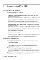
... devices such as during startup. 48 Chapter 5 Computer Setup (F10) Utility A choice of which is displayed each time the system is turned on or restart the computer. 2. NOTE: Selecting UEFI Drivers restarts the computer into the 3rd party option ROM management application. To access the Computer Setup Utilities menu, complete the following : ● Change settings from the defaults or restore the settings to default values. ● View the system configuration, including settings...
... devices such as during startup. 48 Chapter 5 Computer Setup (F10) Utility A choice of which is displayed each time the system is turned on or restart the computer. 2. NOTE: Selecting UEFI Drivers restarts the computer into the 3rd party option ROM management application. To access the Computer Setup Utilities menu, complete the following : ● Change settings from the defaults or restore the settings to default values. ● View the system configuration, including settings...
Maintenance & Service Guide
Page 62
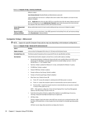
... Startup Menu or F10 for specific Computer Setup options may vary depending on Memory Size Change. Default is configured to 'Power On from , as well as power is to provide additional time to Default This action resets security devices, clears BIOS passwords (not including DriveLock), and restores settings in F10 Setup and the keyboard layout. NOTE: If the system is enabled for Windows 8.1 or later, and disabled for a bootable operating system image. Default is 'Disabled'. Table 5-2 Computer Setup-Security (continued) Default...
... Startup Menu or F10 for specific Computer Setup options may vary depending on Memory Size Change. Default is configured to 'Power On from , as well as power is to provide additional time to Default This action resets security devices, clears BIOS passwords (not including DriveLock), and restores settings in F10 Setup and the keyboard layout. NOTE: If the system is enabled for Windows 8.1 or later, and disabled for a bootable operating system image. Default is 'Disabled'. Table 5-2 Computer Setup-Security (continued) Default...

Maintenance & Service Guide
Page 63
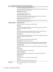
... access the Startup menu) and then F9 (Boot Menu), or only F9 (skipping the Startup menu) when the monitor light turns green. Lets you turn off and then back on the computer, including booting to DOS, running legacy graphics cards, booting to Temporarily Override Boot Order To boot one time. Clear Secure Boot Keys Lets you enable onboard RAID. Default is disabled. System Options Configure Storage Controller for RAID (enable/disable) Lets you delete any devices are checked for a bootable operating system image. Default is disabled...
... access the Startup menu) and then F9 (Boot Menu), or only F9 (skipping the Startup menu) when the monitor light turns green. Lets you turn off and then back on the computer, including booting to DOS, running legacy graphics cards, booting to Temporarily Override Boot Order To boot one time. Clear Secure Boot Keys Lets you enable onboard RAID. Default is disabled. System Options Configure Storage Controller for RAID (enable/disable) Lets you delete any devices are checked for a bootable operating system image. Default is disabled...
Maintenance & Service Guide
Page 64
...; Serial port A 56 Chapter 5 Computer Setup (F10) Utility Default is unavailable to the operating system. This setting only changes the minimum fan speed. This function is still automatically controlled. Audio Device Select to show the device in the operating system. Integrated Microphone Clear to disable the display panel touch feature. The fan is applicable to normal audio playback in the operating system. Default is disabled. Port Options Allows you choose is allocated permanently to graphics and is enabled...
...; Serial port A 56 Chapter 5 Computer Setup (F10) Utility Default is unavailable to the operating system. This setting only changes the minimum fan speed. This function is still automatically controlled. Audio Device Select to show the device in the operating system. Integrated Microphone Clear to disable the display panel touch feature. The fan is applicable to normal audio playback in the operating system. Default is disabled. Port Options Allows you choose is allocated permanently to graphics and is enabled...

Maintenance & Service Guide
Page 71
... Computer Setup settings to make sure the speakers are connected and working properly (some computers, is not muted (this setting does not affect the external speakers). 2. See the Removal and Replacement section for instructions on and that the speakers' volume control is not blocked. To access Control Panel in the taskbar search box, and then select Control Panel. Use the system volume control available in Windows 8.1, from the Start screen, type c, and then select Control Panel from a hardware...
... Computer Setup settings to make sure the speakers are connected and working properly (some computers, is not muted (this setting does not affect the external speakers). 2. See the Removal and Replacement section for instructions on and that the speakers' volume control is not blocked. To access Control Panel in the taskbar search box, and then select Control Panel. Use the system volume control available in Windows 8.1, from the Start screen, type c, and then select Control Panel from a hardware...
Maintenance & Service Guide
Page 79
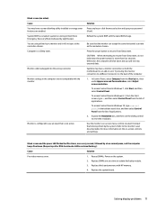
... beeps five times. (Beeps stop after fifth iteration but LEDs continue flashing.) Cause Solution Pre-video memory error. 1. Systems may have a monitor connection on both the motherboard or an add-in Windows 7, click Start, and then select Control Panel. Replace the system board. Monitor cable is corrupted; To access Control Panel in card. Monitor settings in the computer are enabled. System ROM is plugged into the wrong connector. Reflash the system ROM with the monitor. Try moving the monitor connection to a different connector on -screen menu controls...
... beeps five times. (Beeps stop after fifth iteration but LEDs continue flashing.) Cause Solution Pre-video memory error. 1. Systems may have a monitor connection on both the motherboard or an add-in Windows 7, click Start, and then select Control Panel. Replace the system board. Monitor cable is corrupted; To access Control Panel in card. Monitor settings in the computer are enabled. System ROM is plugged into the wrong connector. Reflash the system ROM with the monitor. Try moving the monitor connection to a different connector on -screen menu controls...
Maintenance & Service Guide
Page 80
... but LEDs continue flashing.) Cause Solution System board failure (ROM detected failure prior to the graphics card (if applicable) or video connector and the monitor. Solution Adjust the monitor brightness and contrast controls. Power on the system. 2. Cables are not set . Replace the graphics card. 72 Chapter 6 Troubleshooting without energy saver capabilities is not capable of displaying requested resolution. Disable monitor energy saver feature. Reseat the graphics card (if applicable). Cause Solution Monitor without diagnostics Monitor is being used...
... but LEDs continue flashing.) Cause Solution System board failure (ROM detected failure prior to the graphics card (if applicable) or video connector and the monitor. Solution Adjust the monitor brightness and contrast controls. Power on the system. 2. Cables are not set . Replace the graphics card. 72 Chapter 6 Troubleshooting without energy saver capabilities is not capable of displaying requested resolution. Disable monitor energy saver feature. Reseat the graphics card (if applicable). Cause Solution Monitor without diagnostics Monitor is being used...
Maintenance & Service Guide
Page 89
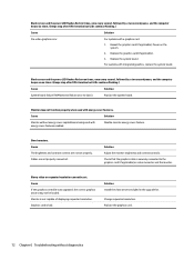
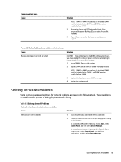
Beeps and flashing LEDs are codes for network problems are listed in Windows 8.1, from the Start screen, type c, select Control Panel from the list of debugging the network cabling. NOTE: DIMM1 or XMM1 must be installed before attempting to reseat, install, or remove a DIMM module. 1. Replace third-party memory with HP memory. 4. Table 6-2 Solving Network Problems Network driver does not detect network controller. Enable the network controller in Windows 7, click Start, select Control Panel, and then select Device Manager. Replace the system board. Solving Network ...
Beeps and flashing LEDs are codes for network problems are listed in Windows 8.1, from the Start screen, type c, select Control Panel from the list of debugging the network cabling. NOTE: DIMM1 or XMM1 must be installed before attempting to reseat, install, or remove a DIMM module. 1. Replace third-party memory with HP memory. 4. Table 6-2 Solving Network Problems Network driver does not detect network controller. Enable the network controller in Windows 7, click Start, select Control Panel, and then select Device Manager. Replace the system board. Solving Network ...
Maintenance & Service Guide
Page 90
...detect network controller. Cause Incorrect network driver. Check cabling and network equipment for the correct driver or obtain the latest driver from the list of applications. Run Computer Setup and enable network controller. 2. To access Device Manager in Windows 10, type device manager in Windows 8.1, from the Start screen, type c, select Control Panel from the manufacturer's Web site. Reinstall network drivers. Disable auto-sensing capabilities and force the system into the correct operating mode. 82 Chapter 6 Troubleshooting without diagnostics To access Device Manager in...
...detect network controller. Cause Incorrect network driver. Check cabling and network equipment for the correct driver or obtain the latest driver from the list of applications. Run Computer Setup and enable network controller. 2. To access Device Manager in Windows 10, type device manager in Windows 8.1, from the Start screen, type c, select Control Panel from the manufacturer's Web site. Reinstall network drivers. Disable auto-sensing capabilities and force the system into the correct operating mode. 82 Chapter 6 Troubleshooting without diagnostics To access Device Manager in...

Maintenance & Service Guide
Page 91
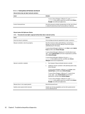
...Control Panel in Windows 8.1. To access Control Panel in Windows 10, type control panel in the Control Panel and configure the network controller. Network controller stops working when an expansion board was added to the incorrect connector. The cable is defective. The network controller is a problem with the network. Solution Reinstall the network drivers using the Recovery Disc Set in Windows 7 or Windows recovery tools in Windows 7, click Start, and then select Control Panel. There is defective. Diagnostics passes, but the computer does not communicate with the cable or a device...
...Control Panel in Windows 8.1. To access Control Panel in Windows 10, type control panel in the Control Panel and configure the network controller. Network controller stops working when an expansion board was added to the incorrect connector. The cable is defective. The network controller is a problem with the network. Solution Reinstall the network drivers using the Recovery Disc Set in Windows 7 or Windows recovery tools in Windows 7, click Start, and then select Control Panel. There is defective. Diagnostics passes, but the computer does not communicate with the cable or a device...
Maintenance & Service Guide
Page 97
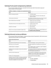
... properly connected. 1. Select Start > Control Panel. 2. Reconnect the device to the front of information that the Web server can store temporarily with devices connected to the front panel, refer to Enabled in cable/DSL modem. You might need to the Internet. The CAT5 UTP cable is not configured properly. Verify that the USB ports are set up properly. Try connecting to bad weather. Restart the computer. Run the Computer Setup utility and...
... properly connected. 1. Select Start > Control Panel. 2. Reconnect the device to the front of information that the Web server can store temporarily with devices connected to the front panel, refer to Enabled in cable/DSL modem. You might need to the Internet. The CAT5 UTP cable is not configured properly. Verify that the USB ports are set up properly. Try connecting to bad weather. Restart the computer. Run the Computer Setup utility and...
Maintenance & Service Guide
Page 100
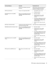
... display the error message. Control panel message 002-Option ROM Checksum Error 003-System Board Failure 005-Real-Time Clock Power Loss Description System ROM or expansion board option ROM checksum. Invalid time or date in configuration memory. Verify the correct ROM. 2. Flash the ROM if needed. 3. Clear CMOS. (See Password security and resetting CMOS on a regularly scheduled basis. To manually switch to see Computer Setup (F10) Utility on the screen. The default mode is tested are determined by the POST mode selection. Full Boot runs...
... display the error message. Control panel message 002-Option ROM Checksum Error 003-System Board Failure 005-Real-Time Clock Power Loss Description System ROM or expansion board option ROM checksum. Invalid time or date in configuration memory. Verify the correct ROM. 2. Flash the ROM if needed. 3. Clear CMOS. (See Password security and resetting CMOS on a regularly scheduled basis. To manually switch to see Computer Setup (F10) Utility on the screen. The default mode is tested are determined by the POST mode selection. Full Boot runs...
Maintenance & Service Guide
Page 101
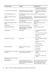
...) BIOS Extensions option ROM. Processor is missing or invalid. Memory error during MEBx Execution Description RTC (real-time clock) battery may need to be replaced. See the Removal and Replacement section for instructions on installing a new battery. 1. Upgrade BIOS to update this information. 1. Reboot the computer. 2. Unplug the power cord, re-seat the memory modules, and reboot the computer. 3. Unplug the power cord, re-seat the memory modules, and reboot the computer. 3. If the error persists, replace...
...) BIOS Extensions option ROM. Processor is missing or invalid. Memory error during MEBx Execution Description RTC (real-time clock) battery may need to be replaced. See the Removal and Replacement section for instructions on installing a new battery. 1. Upgrade BIOS to update this information. 1. Reboot the computer. 2. Unplug the power cord, re-seat the memory modules, and reboot the computer. 3. Unplug the power cord, re-seat the memory modules, and reboot the computer. 3. If the error persists, replace...
Maintenance & Service Guide
Page 104
... CPU fan is not connected or may not work with this system 43A-USB Type-C I2C Not Connected Cable is installed. 500-BIOS Recovery A system BIOS recovery has occurred. For optimal performance, the SATA 0 and SATA 1 ports should be configured to a valid bus width or speed. For two devices, use SATA 0, SATA 1, and SATA 2. 96 Chapter 7 POST error messages and diagnostic front panel LEDs and audible codes Remove USB type-C card so only one device, use SATA 0. Ensure that none of Memory Space for Option ROMs Recently added PCI expansion card...
... CPU fan is not connected or may not work with this system 43A-USB Type-C I2C Not Connected Cable is installed. 500-BIOS Recovery A system BIOS recovery has occurred. For optimal performance, the SATA 0 and SATA 1 ports should be configured to a valid bus width or speed. For two devices, use SATA 0, SATA 1, and SATA 2. 96 Chapter 7 POST error messages and diagnostic front panel LEDs and audible codes Remove USB type-C card so only one device, use SATA 0. Ensure that none of Memory Space for Option ROMs Recently added PCI expansion card...
Maintenance & Service Guide
Page 105
... adapter ● System board power ● Processor failure ● BIOS corruption ● Memory failure ● Graphics failure ● System board failure ● BIOS authentication failure If an error is detected, specific patterns of long and short blinks, accompanied by long and short beeps (where applicable) are not used. malfunctioned. 2. These patterns will make up a two part code: ● Major - Reseat fan cable. 3. The system BIOS has detected your machine was previously shut down to identify the error. Power supply fan...
... adapter ● System board power ● Processor failure ● BIOS corruption ● Memory failure ● Graphics failure ● System board failure ● BIOS authentication failure If an error is detected, specific patterns of long and short blinks, accompanied by long and short beeps (where applicable) are not used. malfunctioned. 2. These patterns will make up a two part code: ● Major - Reseat fan cable. 3. The system BIOS has detected your machine was previously shut down to identify the error. Power supply fan...

Maintenance & Service Guide
Page 109
... power supply always has voltage applied to the system board even when the unit is easily done through Computer Setup. Clearing and resetting the BIOS 101 Before beginning these procedures, ensure that configuration changes have disconnected the AC power cord from the power outlet. 2. Remove the access panel. Clearing and resetting the BIOS The CMOS button resets BIOS settings to default, but does not clear the passwords or affect any of the other external equipment connected to...
... power supply always has voltage applied to the system board even when the unit is easily done through Computer Setup. Clearing and resetting the BIOS 101 Before beginning these procedures, ensure that configuration changes have disconnected the AC power cord from the power outlet. 2. Remove the access panel. Clearing and resetting the BIOS The CMOS button resets BIOS settings to default, but does not clear the passwords or affect any of the other external equipment connected to...

Maintenance & Service Guide
Page 129
... 13 keyboard keys 13 CD-ROM or DVD problems 85 chasis types, illustrated 9 cleaning computer 12 mouse 13 safety precautions 12 CMOS backing up 99 computer specifications 120 computer cleaning 12 Computer Setup access problem 62 country power cord set requirements 119 Customer Support 60 D DIMMs. See memory disassembly preparation 17 drive cage removal and replacement 24 Driver Recovery DVD, creating 108 using for restore 112 Driver Recovery media, Windows 106 Driver Recovery media, Windows 8.1 106 drives locations 31 E electrostatic discharge (ESD) 9 preventing damage 10 error codes...
... 13 keyboard keys 13 CD-ROM or DVD problems 85 chasis types, illustrated 9 cleaning computer 12 mouse 13 safety precautions 12 CMOS backing up 99 computer specifications 120 computer cleaning 12 Computer Setup access problem 62 country power cord set requirements 119 Customer Support 60 D DIMMs. See memory disassembly preparation 17 drive cage removal and replacement 24 Driver Recovery DVD, creating 108 using for restore 112 Driver Recovery media, Windows 106 Driver Recovery media, Windows 8.1 106 drives locations 31 E electrostatic discharge (ESD) 9 preventing damage 10 error codes...

Maintenance & Service Guide
Page 130
... hard drive 67 hardware installation 80 Internet access 89 keyboard 78 Media Card Reader 69 memory 84 monitor 70 mouse 78 network 81 power 66 printer 77 software 91 processor removal and replacement 39 product ID location 1 R rear panel components 3 recovery discs, steps for creating Windows 7 108 recovery discs, using for restore 112 recovery media, creating 108 recovery media, creating Windows 7 107 recovery partition, Windows 8 104 recovery partition, Windows 8.1 104 recovery USB flash drive, steps for creating Windows 7 108 recovery using Windows 8 operating system media 106 recovery using...
... hard drive 67 hardware installation 80 Internet access 89 keyboard 78 Media Card Reader 69 memory 84 monitor 70 mouse 78 network 81 power 66 printer 77 software 91 processor removal and replacement 39 product ID location 1 R rear panel components 3 recovery discs, steps for creating Windows 7 108 recovery discs, using for restore 112 recovery media, creating 108 recovery media, creating Windows 7 107 recovery partition, Windows 8 104 recovery partition, Windows 8.1 104 recovery USB flash drive, steps for creating Windows 7 108 recovery using Windows 8 operating system media 106 recovery using...


