Hardware Reference Guide
Page 5
... the Computer Access Panel 13 Removing the Front Bezel ...14 Removing Bezel Blanks ...14 Replacing the Front Bezel ...15 System Board Connections ...16 Installing Additional Memory ...17 DIMMs ...17 DDR3-SDRAM DIMMs ...17 Populating DIMM Sockets 17 Installing DIMMs ...18 Removing or Installing an Expansion Card 19 Drive Positions ...24 Installing... Removing a Hard Drive from a Drive Bay 32 Installing a Hard Drive into an Internal Drive Bay 33 Installing a Security Lock ...37 Cable Lock ...37 Padlock ...37 HP Business PC Security Lock 38 v
... the Computer Access Panel 13 Removing the Front Bezel ...14 Removing Bezel Blanks ...14 Replacing the Front Bezel ...15 System Board Connections ...16 Installing Additional Memory ...17 DIMMs ...17 DDR3-SDRAM DIMMs ...17 Populating DIMM Sockets 17 Installing DIMMs ...18 Removing or Installing an Expansion Card 19 Drive Positions ...24 Installing... Removing a Hard Drive from a Drive Bay 32 Installing a Hard Drive into an Internal Drive Bay 33 Installing a Security Lock ...37 Cable Lock ...37 Padlock ...37 HP Business PC Security Lock 38 v
Hardware Reference Guide
Page 6
...Bezel Blanks ...47 Replacing the Front Bezel ...48 Changing from Desktop to Tower Configuration 49 System Board Connections ...50 Installing Additional Memory ...51 DIMMs ...51 DDR3-SDRAM DIMMs ...51 Populating DIMM Sockets 51 Installing DIMMs ...52 Removing or Installing an Expansion Card... Drive Bay 69 Removing and Replacing the Primary 3.5-inch Internal Hard Drive 71 Installing a Security Lock ...75 Cable Lock ...75 Padlock ...75 HP Business PC Security Lock 76 Front Bezel Security ...80 Appendix A Battery Replacement ...82 Appendix B Removing and Replacing a Removable 3.5-inch SATA Hard...
...Bezel Blanks ...47 Replacing the Front Bezel ...48 Changing from Desktop to Tower Configuration 49 System Board Connections ...50 Installing Additional Memory ...51 DIMMs ...51 DDR3-SDRAM DIMMs ...51 Populating DIMM Sockets 51 Installing DIMMs ...52 Removing or Installing an Expansion Card... Drive Bay 69 Removing and Replacing the Primary 3.5-inch Internal Hard Drive 71 Installing a Security Lock ...75 Cable Lock ...75 Padlock ...75 HP Business PC Security Lock 76 Front Bezel Security ...80 Appendix A Battery Replacement ...82 Appendix B Removing and Replacing a Removable 3.5-inch SATA Hard...
Hardware Reference Guide
Page 14
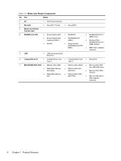
... Card Type 1 ● CompactFlash Card Type 2 ● MicroDrive 7 MS PRO/MS PRO DUO ● Memory Stick (MS) ● Memory Stick Select ● Memory Stick PRO ● MagicGate Memory Stick (MG) ● Memory Stick Duo (MS Duo) Duo (MS PRO Duo) ● Memory Stick PRO- ● MagicGate Memory Duo ● Memory Stick PRO (MS PRO) HG Duo ● Memory Stick Micro (M2) (adapter required) 6 Chapter 1 Product Features
... Card Type 1 ● CompactFlash Card Type 2 ● MicroDrive 7 MS PRO/MS PRO DUO ● Memory Stick (MS) ● Memory Stick Select ● Memory Stick PRO ● MagicGate Memory Stick (MG) ● Memory Stick Duo (MS Duo) Duo (MS PRO Duo) ● Memory Stick PRO- ● MagicGate Memory Duo ● Memory Stick PRO (MS PRO) HG Duo ● Memory Stick Micro (M2) (adapter required) 6 Chapter 1 Product Features
Hardware Reference Guide
Page 24
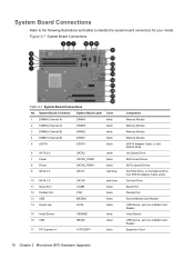
... MEDIA2 HLCK dark blue black black black black 15 Hood Sensor 16 USB HSENSE MEDIA white black 17 PCI Express x1 X1PCIEXP1 black Component Memory Module Memory Module Memory Module Memory Module eSATA Adapter Cable, or 2nd Optical Drive 1st Optical Drive SATA Hard Drives SATA Optical Drives 2nd Hard Drive, or 2nd Optical...
... MEDIA2 HLCK dark blue black black black black 15 Hood Sensor 16 USB HSENSE MEDIA white black 17 PCI Express x1 X1PCIEXP1 black Component Memory Module Memory Module Memory Module Memory Module eSATA Adapter Cable, or 2nd Optical Drive 1st Optical Drive SATA Hard Drives SATA Optical Drives 2nd Hard Drive, or 2nd Optical...
Hardware Reference Guide
Page 25
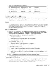
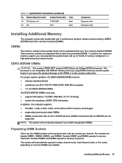
...be populated with up to the DIMM or invoke system malfunction. Sockets DIMM3 and DIMM4 operate in memory channel B. To achieve the maximum memory support, you plug DDR3U memory into the system board, it can populate the system board with two sockets per channel. For proper... ● DIMMs constructed with at least one preinstalled DIMM. Sockets DIMM1 and DIMM2 operate in memory channel A. Installing Additional Memory 17 Table 2-1 System Board Connections (continued) No. DIMMs The memory sockets on the system board, with up to a x4 19 PCI Express x16 X16PCIEXP 20...
...be populated with up to the DIMM or invoke system malfunction. Sockets DIMM3 and DIMM4 operate in memory channel B. To achieve the maximum memory support, you plug DDR3U memory into the system board, it can populate the system board with two sockets per channel. For proper... ● DIMMs constructed with at least one preinstalled DIMM. Sockets DIMM1 and DIMM2 operate in memory channel A. Installing Additional Memory 17 Table 2-1 System Board Connections (continued) No. DIMMs The memory sockets on the system board, with up to a x4 19 PCI Express x16 X16PCIEXP 20...

Hardware Reference Guide
Page 26
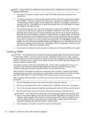
...ensure that you are discharged of static electricity by the slowest DIMM in the system. NOTE: Single channel and unbalanced dual channel memory configurations will result in inferior graphics performance. ● The system will operate in single channel mode if the DIMM sockets are installed... contacts. CAUTION: You must disconnect the power cord and wait approximately 30 seconds for the power to Channel A. Adding or removing memory modules while voltage is determined by briefly touching a grounded metal object. For optimal speed, the channels should be balanced so that ...
...ensure that you are discharged of static electricity by the slowest DIMM in the system. NOTE: Single channel and unbalanced dual channel memory configurations will result in inferior graphics performance. ● The system will operate in single channel mode if the DIMM sockets are installed... contacts. CAUTION: You must disconnect the power cord and wait approximately 30 seconds for the power to Channel A. Adding or removing memory modules while voltage is determined by briefly touching a grounded metal object. For optimal speed, the channels should be balanced so that ...
Hardware Reference Guide
Page 27
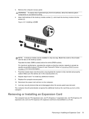
...can be installed in the closed position (3). 8. Make sure the latches are in only one PCI Express x16 expansion slot that the memory capacity is fully inserted and properly seated. Replace the computer access panel. 10. Refer to cool before the white DIMM sockets. The... computer should automatically recognize the additional memory the next time you turn on the memory socket. Removing or Installing an Expansion Card 19 Removing or Installing an Expansion Card The computer has one PCI expansion ...
...can be installed in the closed position (3). 8. Make sure the latches are in only one PCI Express x16 expansion slot that the memory capacity is fully inserted and properly seated. Replace the computer access panel. 10. Refer to cool before the white DIMM sockets. The... computer should automatically recognize the additional memory the next time you turn on the memory socket. Removing or Installing an Expansion Card 19 Removing or Installing an Expansion Card The computer has one PCI expansion ...
Hardware Reference Guide
Page 58
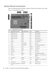
... 3-7 System Board Connections Table 3-1 System Board Connections No. System Board Connections Refer to the following illustration and table to a x4 black white Component Memory Module Memory Module Memory Module Memory Module eSATA Adapter Cable 1st Optical Drive (unused) SATA Optical and Hard Drives 2nd Hard Drive 1st Hard Drive Serial Port Parallel Port Second...
... 3-7 System Board Connections Table 3-1 System Board Connections No. System Board Connections Refer to the following illustration and table to a x4 black white Component Memory Module Memory Module Memory Module Memory Module eSATA Adapter Cable 1st Optical Drive (unused) SATA Optical and Hard Drives 2nd Hard Drive 1st Hard Drive Serial Port Parallel Port Second...
Hardware Reference Guide
Page 59
...PCI Express x16 X16PCIEXP 20 PCI PCI1 Color black white Component Expansion Card Expansion Card Installing Additional Memory The computer comes with DDR3U memory and if you plug DDR3U memory into the system board, it can cause the physical damage to the DIMM or invoke system ...malfunction. The processor is not compatible with double data rate 3 synchronous dynamic random access memory (DDR3SDRAM) dual inline memory modules (DIMMs). The system will not operate properly if you can be : ● industry-standard 240-pin ● unbuffered...
...PCI Express x16 X16PCIEXP 20 PCI PCI1 Color black white Component Expansion Card Expansion Card Installing Additional Memory The computer comes with DDR3U memory and if you plug DDR3U memory into the system board, it can cause the physical damage to the DIMM or invoke system ...malfunction. The processor is not compatible with double data rate 3 synchronous dynamic random access memory (DDR3SDRAM) dual inline memory modules (DIMMs). The system will not operate properly if you can be : ● industry-standard 240-pin ● unbuffered...
Hardware Reference Guide
Page 60
..., remove the computer from the power outlet and disconnect any of static electricity by the slowest DIMM in the system. For more memory than the other . When handling a memory module, be assigned to single channel. Disconnect the power cord from the stand. 52 Chapter 3 Small Form Factor (SFF) Hardware...DIMM sockets are populated in one channel will have gold-plated metal contacts. The technology and device width can damage the electronic components of memory is on page 92. In flex mode, the channel populated with each other , the larger amount should be careful not to dual ...
..., remove the computer from the power outlet and disconnect any of static electricity by the slowest DIMM in the system. For more memory than the other . When handling a memory module, be assigned to single channel. Disconnect the power cord from the stand. 52 Chapter 3 Small Form Factor (SFF) Hardware...DIMM sockets are populated in one channel will have gold-plated metal contacts. The technology and device width can damage the electronic components of memory is on page 92. In flex mode, the channel populated with each other , the larger amount should be careful not to dual ...
Hardware Reference Guide
Page 61
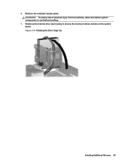
Figure 3-8 Rotating the Drive Cage Up Installing Additional Memory 53 Remove the computer access panel. Rotate up the internal drive bay housing to cool before touching. 7. To reduce risk of personal injury from hot surfaces, allow the internal system components to access the memory module sockets on the system board. 6. WARNING!
Figure 3-8 Rotating the Drive Cage Up Installing Additional Memory 53 Remove the computer access panel. Rotate up the internal drive bay housing to cool before touching. 7. To reduce risk of personal injury from hot surfaces, allow the internal system components to access the memory module sockets on the system board. 6. WARNING!
Hardware Reference Guide
Page 62
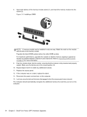
...the computer. 54 Chapter 3 Small Form Factor (SFF) Hardware Upgrades Lock any additional modules. 11. Open both latches of the memory module socket (1), and insert the memory module into the socket, ensuring that the module is spread as equally as possible between Channel A and Channel B. Populate the ...black DIMM sockets before the white DIMM sockets. Push the module down into the socket (2). Refer to install any security devices that the memory capacity is fully inserted and properly seated. Match the notch on the module with the tab on a stand, replace the stand. 13. ...
...the computer. 54 Chapter 3 Small Form Factor (SFF) Hardware Upgrades Lock any additional modules. 11. Open both latches of the memory module socket (1), and insert the memory module into the socket, ensuring that the module is spread as equally as possible between Channel A and Channel B. Populate the ...black DIMM sockets before the white DIMM sockets. Push the module down into the socket (2). Refer to install any security devices that the memory capacity is fully inserted and properly seated. Match the notch on the module with the tab on a stand, replace the stand. 13. ...
Hardware Reference Guide
Page 103
... 3 G guide screws MT location 25 SFF location 60 C computer operating guidelines 93 D DIMMs. See memory drives MT cable connections 25 MT installation 25 MT locations 24 SFF cable connections 60 SFF installation 60 SFF...drive 71 SFF media card reader 69 SFF memory 51 SFF optical drive 64 K keyboard components 7 Windows Logo key 8 L locks MT front bezel 42 MT HP Business PC Security Lock 38 MT padlock 37... SFF HP Business PC Security Lock 76 SFF padlock 75 Smart Cover Lock 90 M media card reader features 5 MT installation 29 MT removal 27 SFF installation 69 SFF removal 67 memory MT installation...
... 3 G guide screws MT location 25 SFF location 60 C computer operating guidelines 93 D DIMMs. See memory drives MT cable connections 25 MT installation 25 MT locations 24 SFF cable connections 60 SFF installation 60 SFF...drive 71 SFF media card reader 69 SFF memory 51 SFF optical drive 64 K keyboard components 7 Windows Logo key 8 L locks MT front bezel 42 MT HP Business PC Security Lock 38 MT padlock 37... SFF HP Business PC Security Lock 76 SFF padlock 75 Smart Cover Lock 90 M media card reader features 5 MT installation 29 MT removal 27 SFF installation 69 SFF removal 67 memory MT installation...
Hardware Reference Guide
Page 104
... reader 67 SFF optical drive 62 Smart Cover Lock 90 S security MT front bezel 42 MT HP Business PC Security Lock 38 MT padlock 37 SFF cable lock 37, 75 SFF front bezel 80 SFF HP Business PC Security Lock 76 SFF padlock 75 Smart Cover Lock 90 serial number locations 10... shipping preparation 94 Smart Cover Lock 90 specifications MT memory 17 SFF memory 51 system board connections MT 16 SFF 50 T tower conversion SFF...
... reader 67 SFF optical drive 62 Smart Cover Lock 90 S security MT front bezel 42 MT HP Business PC Security Lock 38 MT padlock 37 SFF cable lock 37, 75 SFF front bezel 80 SFF HP Business PC Security Lock 76 SFF padlock 75 Smart Cover Lock 90 serial number locations 10... shipping preparation 94 Smart Cover Lock 90 specifications MT memory 17 SFF memory 51 system board connections MT 16 SFF 50 T tower conversion SFF...
Illustrated Parts & Service Map HP Compaq Pro 6305 Business PC Microtower
Page 2
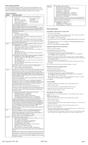
... 1. Check DIMMs for bent or missing pins. Replace system board. 214-DIMM Configuration Warning Populated DIMM configura- Replace keyboard. HP Compaq Pro 6305, MT 706895-001 page 2 Expansion board option ROM checksum 1. Clear CMOS memory, reboot 4. Remove DIMMs singularly and reboot to boot followed by a 2 second pause 10 blinks, 1 blink every second Bad option...
... 1. Check DIMMs for bent or missing pins. Replace system board. 214-DIMM Configuration Warning Populated DIMM configura- Replace keyboard. HP Compaq Pro 6305, MT 706895-001 page 2 Expansion board option ROM checksum 1. Clear CMOS memory, reboot 4. Remove DIMMs singularly and reboot to boot followed by a 2 second pause 10 blinks, 1 blink every second Bad option...
Illustrated Parts & Service Map HP Compaq Pro 6305 Business PC Microtower
Page 3
...speed/stepping • Chassis serial number • Cache size (L1/L2/L3) • Asset tracking number • Installed memory size/speed/chan About - Device Security - Hardware Power Management - Allows you set resources or disable Legacy devices. enable/disable ... screen 5. Locate the header and jumper. 4. This clears the current passwords and disables the password features. 8. HP Compaq Pro 6305, MT 706895-001 page 3 Computer Setup Menu Heading Option/Description File System Information - Master Boot Record Security may...
...speed/stepping • Chassis serial number • Cache size (L1/L2/L3) • Asset tracking number • Installed memory size/speed/chan About - Device Security - Hardware Power Management - Allows you set resources or disable Legacy devices. enable/disable ... screen 5. Locate the header and jumper. 4. This clears the current passwords and disables the password features. 8. HP Compaq Pro 6305, MT 706895-001 page 3 Computer Setup Menu Heading Option/Description File System Information - Master Boot Record Security may...
Illustrated Parts & Service Map HP Compaq Pro 6305 Business PC Microtower
Page 4
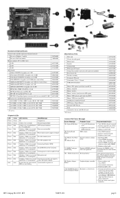
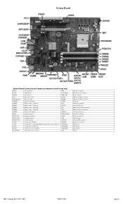
... CHFAN Fan connector PWR CMD BAT RTC battery socket MEDIA PROCESSOR Processor socket MEDIA2 PWRCPU CPU power connector COMB DIMM4 Memory socket - Channel A IN/OUT DIMM2 Memory socket - Channel B PS2 DIMM1 Memory socket - Channel B VGA PB/LED Power switch connector CHFAN2 SPKR Speaker connector DISPLAYPORT FRNT AUD Front panel connector ... connector Hood lock connector USB connectors Network+USB connectors Hood sensor connector PCIe X1 slot PCIe X16 slot PCIe X16 slot PCI slot HP Compaq Pro 6305, MT 706895-001 page 4 Channel A PAR DIMM3 Memory socket -
... CHFAN Fan connector PWR CMD BAT RTC battery socket MEDIA PROCESSOR Processor socket MEDIA2 PWRCPU CPU power connector COMB DIMM4 Memory socket - Channel A IN/OUT DIMM2 Memory socket - Channel B PS2 DIMM1 Memory socket - Channel B VGA PB/LED Power switch connector CHFAN2 SPKR Speaker connector DISPLAYPORT FRNT AUD Front panel connector ... connector Hood lock connector USB connectors Network+USB connectors Hood sensor connector PCIe X1 slot PCIe X16 slot PCIe X16 slot PCI slot HP Compaq Pro 6305, MT 706895-001 page 4 Channel A PAR DIMM3 Memory socket -
Maintenance and Service Guide HP Compaq Pro 6305 Microtower Business PC HP Compaq Pro 6305 Small Form Factor Business PC
Page 7
Front Bezel Security ...52 Bezel Blanks ...54 Memory ...55 DIMMs ...55 DDR3-SDRAM DIMMs ...55 Populating DIMM Sockets 56 Installing DIMMs ...56 Expansion Cards ...58 System Board Connections ...62 Drives ...63 Drive Positions ...... Replacement Procedures Small Form Factor (SFF) Chassis 92 Preparation for Disassembly ...92 Access Panel ...93 Front Bezel ...94 Front Bezel Security ...95 Bezel Blanks ...97 Memory ...98 DIMMs ...98 DDR3-SDRAM DIMMs ...98 Populating DIMM Sockets 98 Installing DIMMs ...99 Expansion Card ...101 System Board Connections ...105 Drives ...106 Drive Positions...
Front Bezel Security ...52 Bezel Blanks ...54 Memory ...55 DIMMs ...55 DDR3-SDRAM DIMMs ...55 Populating DIMM Sockets 56 Installing DIMMs ...56 Expansion Cards ...58 System Board Connections ...62 Drives ...63 Drive Positions ...... Replacement Procedures Small Form Factor (SFF) Chassis 92 Preparation for Disassembly ...92 Access Panel ...93 Front Bezel ...94 Front Bezel Security ...95 Bezel Blanks ...97 Memory ...98 DIMMs ...98 DDR3-SDRAM DIMMs ...98 Populating DIMM Sockets 98 Installing DIMMs ...99 Expansion Card ...101 System Board Connections ...105 Drives ...106 Drive Positions...
Maintenance and Service Guide HP Compaq Pro 6305 Microtower Business PC HP Compaq Pro 6305 Small Form Factor Business PC
Page 8
... ...150 Solving Audio Problems ...154 Solving Printer Problems ...156 Solving Keyboard and Mouse Problems 157 Solving Hardware Installation Problems 159 Solving Network Problems ...161 Solving Memory Problems ...163 Solving Processor Problems ...165 Solving CD-ROM and DVD Problems 165 Solving USB Flash Drive Problems 168 Solving Front Panel Component Problems 169...
... ...150 Solving Audio Problems ...154 Solving Printer Problems ...156 Solving Keyboard and Mouse Problems 157 Solving Hardware Installation Problems 159 Solving Network Problems ...161 Solving Memory Problems ...163 Solving Processor Problems ...165 Solving CD-ROM and DVD Problems 165 Solving USB Flash Drive Problems 168 Solving Front Panel Component Problems 169...
Maintenance and Service Guide HP Compaq Pro 6305 Microtower Business PC HP Compaq Pro 6305 Small Form Factor Business PC
Page 19
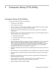
...or parallel ports, audio, or embedded NIC, so that controls access to change , or verify the system configuration, including settings for processor, graphics, memory, audio, storage, communications, and input devices. ● Modify the boot order of the diagnostic tests run during POST, press any key (except F1...9679; Establish an Ownership Tag, the text of which is faster than Full Boot but does not run all of bootable devices such as memory count, product name, and other non-error text messages. Post Messages Disabled suppresses most POST messages, such as hard drives, optical drives,...
...or parallel ports, audio, or embedded NIC, so that controls access to change , or verify the system configuration, including settings for processor, graphics, memory, audio, storage, communications, and input devices. ● Modify the boot order of the diagnostic tests run during POST, press any key (except F1...9679; Establish an Ownership Tag, the text of which is faster than Full Boot but does not run all of bootable devices such as memory count, product name, and other non-error text messages. Post Messages Disabled suppresses most POST messages, such as hard drives, optical drives,...


