Maintenance and Service Guide
Page 3
... Operation...1-14 Specifications ...1-18 Internal Design...1-24 Removal and Replacement 2-1 Disassembly Flowchart ...2-3 Removing the Battery ...2-4 Removing an SDRAM Module...2-5 Removing the Wireless LAN Mini PCI Card 2-7 Removing the Hard Disk Drive...2-9 Recovering the Factory Software...2-11 Replacing Small Parts ...2-12 Removing the Keyboard Cover...2-13 Removing the Speaker Assembly ...2-15 Removing the Keyboard ...2-16 Removing the Switchboard PCA ...2-19 Removing the CD/DVD Drive...2-20 Removing the Display Assembly...2-23 Removing the Top Case ...2-26 Removing the Floppy Drive...
... Operation...1-14 Specifications ...1-18 Internal Design...1-24 Removal and Replacement 2-1 Disassembly Flowchart ...2-3 Removing the Battery ...2-4 Removing an SDRAM Module...2-5 Removing the Wireless LAN Mini PCI Card 2-7 Removing the Hard Disk Drive...2-9 Recovering the Factory Software...2-11 Replacing Small Parts ...2-12 Removing the Keyboard Cover...2-13 Removing the Speaker Assembly ...2-15 Removing the Keyboard ...2-16 Removing the Switchboard PCA ...2-19 Removing the CD/DVD Drive...2-20 Removing the Display Assembly...2-23 Removing the Top Case ...2-26 Removing the Floppy Drive...
Maintenance and Service Guide
Page 4
... (with Fan 2-41 Figure 2-27. Removing the Hard Disk Drive Guide 2-53 iv Service Manual Resetting the Notebook ...1-17 Figure 1-8. Replaceable Module Diagram 1-24 Figure 2-1. Removing an SDRAM Module 2-6 Figure 2-5. Removing the Switchboard PCA 2-19 Figure 2-15. Removing the Top Case Screws 2-29 Figure 2-20. Removing the Top Case Screws 2-30 Figure 2-21. Intel CPU Module Removal 2-45 Figure 2-29. Removing the Motherboard 2-51 Figure 2-35. Figures Figure 1-1. Removing the Keyboard Cover 2-14 Figure 2-10. Removing the...
... (with Fan 2-41 Figure 2-27. Removing the Hard Disk Drive Guide 2-53 iv Service Manual Resetting the Notebook ...1-17 Figure 1-8. Replaceable Module Diagram 1-24 Figure 2-1. Removing an SDRAM Module 2-6 Figure 2-5. Removing the Switchboard PCA 2-19 Figure 2-15. Removing the Top Case Screws 2-29 Figure 2-20. Removing the Top Case Screws 2-30 Figure 2-21. Intel CPU Module Removal 2-45 Figure 2-29. Removing the Motherboard 2-51 Figure 2-35. Figures Figure 1-1. Removing the Keyboard Cover 2-14 Figure 2-10. Removing the...
Maintenance and Service Guide
Page 6
... updates for servicing the HP Pavilion ze5600, ze5500, ze5400, ze5300, ze5200, ze4700, ze4600, ze4500, ze4400, ze4300, ze4200, and ze4100 Notebook PCs, HP Compaq nx9010, nx9008, nx9005, and nx9000 Notebook PCs, Compaq Evo Notebook 1050v and 1010v Series, and Compaq Presario 2500, 2100, and 1100 Series Mobile PCs. and Canada. Introduction This manual provides reference information for Windows operating systems. Service Manual vii These notebook models use by authorized service personnel while installing, servicing, and repairing these notebooks...
... updates for servicing the HP Pavilion ze5600, ze5500, ze5400, ze5300, ze5200, ze4700, ze4600, ze4500, ze4400, ze4300, ze4200, and ze4100 Notebook PCs, HP Compaq nx9010, nx9008, nx9005, and nx9000 Notebook PCs, Compaq Evo Notebook 1050v and 1010v Series, and Compaq Presario 2500, 2100, and 1100 Series Mobile PCs. and Canada. Introduction This manual provides reference information for Windows operating systems. Service Manual vii These notebook models use by authorized service personnel while installing, servicing, and repairing these notebooks...
Maintenance and Service Guide
Page 26
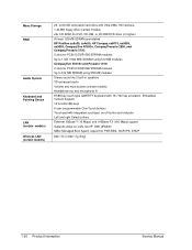
.../88-key touch-type QWERTY keyboard with integrated scroll pad, on-off button and indicator Left and right Select buttons Ethernet 10Base-T (10 Mbps) and 100Base-TX (100 Mbps) support Supports wake-on-LAN, fast IP, DMI, dRMON MBA (Managed Boot Agent) support for PXE/BINL, NCP/IPX, DHCP 802.11b or 802.11g (54g) 1-20 Product Information Service Manual Mass Storage RAM Audio System Keyboard and Pointing Device LAN (certain models) Wireless LAN (certain models...
.../88-key touch-type QWERTY keyboard with integrated scroll pad, on-off button and indicator Left and right Select buttons Ethernet 10Base-T (10 Mbps) and 100Base-TX (100 Mbps) support Supports wake-on-LAN, fast IP, DMI, dRMON MBA (Managed Boot Agent) support for PXE/BINL, NCP/IPX, DHCP 802.11b or 802.11g (54g) 1-20 Product Information Service Manual Mass Storage RAM Audio System Keyboard and Pointing Device LAN (certain models) Wireless LAN (certain models...
Maintenance and Service Guide
Page 89
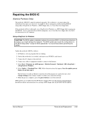
.... Service Manual Removal and Replacement 2-59 If the notebook will boot sufficiently, use a Crisis Recovery floppy disk. In Windows, exit any PCMCIA cards from it . Repairing the BIOS IC (Service Partners Only) The notebook's BIOS IC cannot be able to reprogram a malfunctioning BIOS IC using either e-DiagTools for Windows, a BIOS floppy disk, or a Crisis Recovery floppy disk. Select Update, > Download New > OK. When the process completes, press the power button to reprogram the BIOS IC. Installation utilities and instructions for creating a BIOS floppy disk are...
.... Service Manual Removal and Replacement 2-59 If the notebook will boot sufficiently, use a Crisis Recovery floppy disk. In Windows, exit any PCMCIA cards from it . Repairing the BIOS IC (Service Partners Only) The notebook's BIOS IC cannot be able to reprogram a malfunctioning BIOS IC using either e-DiagTools for Windows, a BIOS floppy disk, or a Crisis Recovery floppy disk. Select Update, > Download New > OK. When the process completes, press the power button to reprogram the BIOS IC. Installation utilities and instructions for creating a BIOS floppy disk are...
Maintenance and Service Guide
Page 100
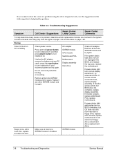
... does not start from floppy drive, reload hard drive, replace hard drive. 3-8 Troubleshooting and Diagnostics Service Manual CPU module Switchboard PCA Motherboard Display assembly Hard drive Beeps once, spins hard disk, repeats, but BIOS does not complete, replace display assembly. SDRAM module Check AC adapter. If power status light and display turn on AC or battery Check power source. Do not use the suggestions in the following table to help determine likely causes of a problem using the above diagnostic tools, use touch pad while booting or...
... does not start from floppy drive, reload hard drive, replace hard drive. 3-8 Troubleshooting and Diagnostics Service Manual CPU module Switchboard PCA Motherboard Display assembly Hard drive Beeps once, spins hard disk, repeats, but BIOS does not complete, replace display assembly. SDRAM module Check AC adapter. If power status light and display turn on AC or battery Check power source. Do not use the suggestions in the following table to help determine likely causes of a problem using the above diagnostic tools, use touch pad while booting or...
Maintenance and Service Guide
Page 101
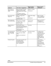
... connected correctly. Password removal is bootable. Power Service Manual Troubleshooting and Diagnostics 3-9 Make sure CD is restricted to reinstall factory software onto hard drive, replace hard drive. Check boot order in disk's Properties sheet to check default boot order. User must call Technical Support and provide proof of ownership. Use Disk Defragmenter to check default boot order. Remove and reinstall hard drive. If available, try another battery. Use BIOS Setup to check hard disk. Check battery contacts. Make sure floppy disk is properly installed and fully charged...
... connected correctly. Password removal is bootable. Power Service Manual Troubleshooting and Diagnostics 3-9 Make sure CD is restricted to reinstall factory software onto hard drive, replace hard drive. Check boot order in disk's Properties sheet to check default boot order. User must call Technical Support and provide proof of ownership. Use Disk Defragmenter to check default boot order. Remove and reinstall hard drive. If available, try another battery. Use BIOS Setup to check hard disk. Check battery contacts. Make sure floppy disk is properly installed and fully charged...
Maintenance and Service Guide
Page 103
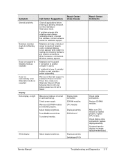
... in Power in Control Panel. Make sure CPU module is busy, it normally finishes current operation before entering (or allowing notebook to Never. Service Manual Troubleshooting and Diagnostics 3-11 If notebook is installed properly, replace CPU module. Check power supply. Try external monitor. Check display cable connections, replace display assembly. If external monitor displays no light Call Center: Suggestions Close all applications before suspending. Contact software vendor for AC and battery power are installed properly. Adjust display brightness...
... in Power in Control Panel. Make sure CPU module is busy, it normally finishes current operation before entering (or allowing notebook to Never. Service Manual Troubleshooting and Diagnostics 3-11 If notebook is installed properly, replace CPU module. Check power supply. Try external monitor. Check display cable connections, replace display assembly. If external monitor displays no light Call Center: Suggestions Close all applications before suspending. Contact software vendor for AC and battery power are installed properly. Adjust display brightness...
Maintenance and Service Guide
Page 104
... or light discoloration visible when display is damaged, drive may not operate properly. Press Fn+F5 several times. Remove and reinstall hard drive. Symptom Erratic display Call Center: Suggestions Bright or missing pixels or lines. Check hard disk installation. Check display cable connection. See quality statement on External display does not work Hard disk Hard disk never spins Hard disk makes clunking or scratching noise Hard disk makes buzzing or whining noise Check connections. Try display on screen Repair Center: Comments Check display cable connection...
... or light discoloration visible when display is damaged, drive may not operate properly. Press Fn+F5 several times. Remove and reinstall hard drive. Symptom Erratic display Call Center: Suggestions Bright or missing pixels or lines. Check hard disk installation. Check display cable connection. See quality statement on External display does not work Hard disk Hard disk never spins Hard disk makes clunking or scratching noise Hard disk makes buzzing or whining noise Check connections. Try display on screen Repair Center: Comments Check display cable connection...
Maintenance and Service Guide
Page 107
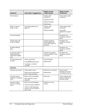
... Manual Troubleshooting and Diagnostics 3-15 Make sure speaker assembly cable is installed from \hp\drivers\TouchPad.) Top case Motherboard Top case Motherboard Top case Motherboard Make sure C drive has adequate free space. Check whether sound is connected, Use BIOS Setup to check settings. Delete temporary and unneeded files. Use an external microphone (internal microphone normally not included). By default, touch pad is disabled if external PS/2 mouse is enabled (mute button and software controls). SDRAM module SDRAM module Increase sound volume. Check software...
... Manual Troubleshooting and Diagnostics 3-15 Make sure speaker assembly cable is installed from \hp\drivers\TouchPad.) Top case Motherboard Top case Motherboard Top case Motherboard Make sure C drive has adequate free space. Check whether sound is connected, Use BIOS Setup to check settings. Delete temporary and unneeded files. Use an external microphone (internal microphone normally not included). By default, touch pad is disabled if external PS/2 mouse is enabled (mute button and software controls). SDRAM module SDRAM module Increase sound volume. Check software...
Maintenance and Service Guide
Page 109
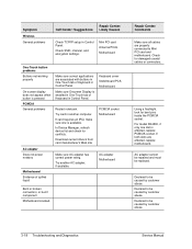
... operation. If green light next to LAN port does not light, LAN cable may not be connected to another network station (if applicable). Motherboard Infrared is disabled and no more than 1 meter apart. Maximum cable length is 100 meters (330 feet). Test LAN with ECP parallel port. Symptom LAN/network General problems Infrared General problems Call Center: Suggestions Repair Center: Likely Causes Check cables and connections. Try to enable the infrared port. Open Hardware Device Manager. Motherboard Repair Center: Comments Service Manual Troubleshooting...
... operation. If green light next to LAN port does not light, LAN cable may not be connected to another network station (if applicable). Motherboard Infrared is disabled and no more than 1 meter apart. Maximum cable length is 100 meters (330 feet). Test LAN with ECP parallel port. Symptom LAN/network General problems Infrared General problems Call Center: Suggestions Repair Center: Likely Causes Check cables and connections. Try to enable the infrared port. Open Hardware Device Manager. Motherboard Repair Center: Comments Service Manual Troubleshooting...
Maintenance and Service Guide
Page 110
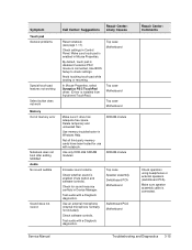
... Control Panel. AC adapter cannot be repaired and must be caused by customer abuse. Mini PCI card Antenna PCAs Motherboard One-Touch button problems Buttons not working properly On-screen display does not appear when button is affected, replace PCMCIA socket. Try another computer. Restart notebook. Keyboard cover Switchboard PCA Motherboard PCMCIA socket Motherboard AC adapter Motherboard Bent or broken connectors, or burnt component Motherboard cracked. Declared to Mini PCI card and motherboard. In Device Manager, refresh device list...
... Control Panel. AC adapter cannot be repaired and must be caused by customer abuse. Mini PCI card Antenna PCAs Motherboard One-Touch button problems Buttons not working properly On-screen display does not appear when button is affected, replace PCMCIA socket. Try another computer. Restart notebook. Keyboard cover Switchboard PCA Motherboard PCMCIA socket Motherboard AC adapter Motherboard Bent or broken connectors, or burnt component Motherboard cracked. Declared to Mini PCI card and motherboard. In Device Manager, refresh device list...
Maintenance and Service Guide
Page 113
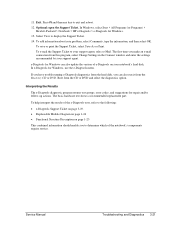
... or DVD and select the diagnostics option. In Windows, select Start > All Programs (or Programs) > Hewlett-Packard > Notebook > HP e-Diagtools > e-Diagtools for Windows can also run it from the Recovery CD or DVD. Press F3 and then any key to the following: • e-Diagtools Support Ticket on page 3-19. • Replaceable Module Diagram on page 1-24 • Functional Structure Description on your problem, select Comments, type the...
... or DVD and select the diagnostics option. In Windows, select Start > All Programs (or Programs) > Hewlett-Packard > Notebook > HP e-Diagtools > e-Diagtools for Windows can also run it from the Recovery CD or DVD. Press F3 and then any key to the following: • e-Diagtools Support Ticket on page 3-19. • Replaceable Module Diagram on page 1-24 • Functional Structure Description on your problem, select Comments, type the...
Maintenance and Service Guide
Page 114
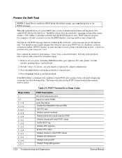
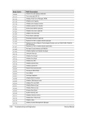
... a beep code indicating an error, confirm the problem using other diagnostic tools. Power-On Self-Test NOTE: If Quiet Boot is enabled in BIOS Setup (the default setting), press esc during boot to start the notebook. Remove all POST messages indicate a failure in which the terminal error occurred. Press the power button to see the following table). Beep Codes 1 1-2 1-1-1-3 1-1-1-4 1-1-2-1 1-1-2-3 1-1-2-4 1-1-3-1 1-1-3-2 1-1-3-3 1-1-3-4 1-1-4-1 1-1-4-3 1-1-4-4 1-2-1-1 Table 3-4. POST indicates progress by performing a "clean" boot, as a hardware, software, or firmware failure...
... a beep code indicating an error, confirm the problem using other diagnostic tools. Power-On Self-Test NOTE: If Quiet Boot is enabled in BIOS Setup (the default setting), press esc during boot to start the notebook. Remove all POST messages indicate a failure in which the terminal error occurred. Press the power button to see the following table). Beep Codes 1 1-2 1-1-1-3 1-1-1-4 1-1-2-1 1-1-2-3 1-1-2-4 1-1-3-1 1-1-3-2 1-1-3-3 1-1-3-4 1-1-4-1 1-1-4-3 1-1-4-4 1-2-1-1 Table 3-4. POST indicates progress by performing a "clean" boot, as a hardware, software, or firmware failure...
Maintenance and Service Guide
Page 115
... with CMOS values Initialize extended memory for ROMPilot Initialize interrupt vectors POST device initialization Check ROM copyright notice Initialize I20 support Check video configuration against CMOS Initialize PCI bus and devices Initialize all video adapters in system QuietBoot start (optional) Shadow video BIOS ROM Display BIOS copyright notice Troubleshooting and Diagnostics 3-23 or wrong type or no RAM installed Initialize POST Memory Manager Clear 512 KB base RAM RAM failure on address line xxxx RAM failure on motherboard) Set ES...
... with CMOS values Initialize extended memory for ROMPilot Initialize interrupt vectors POST device initialization Check ROM copyright notice Initialize I20 support Check video configuration against CMOS Initialize PCI bus and devices Initialize all video adapters in system QuietBoot start (optional) Shadow video BIOS ROM Display BIOS copyright notice Troubleshooting and Diagnostics 3-23 or wrong type or no RAM installed Initialize POST Memory Manager Clear 512 KB base RAM RAM failure on address line xxxx RAM failure on motherboard) Set ES...

Maintenance and Service Guide
Page 117
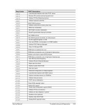
... drives (optional) Initialize hard-disk controllers Initialize local-bus hard-disk controllers Jump to UserPatch2 Build MPTABLE for multi-processor boards Install CD-ROM for boot Clear huge ES segment register Fix up Multi Processor table Check for SMART Drive (optional) Shadow option ROMs Set up Power Management Initialize security engine (optional) Enable hardware interrupts Determine number of ATA and SCSI drives Set time of day Check key lock Initialize typematic rate Erase F2 prompt Scan for F2 keystroke Enter SETUP Clear Boot...
... drives (optional) Initialize hard-disk controllers Initialize local-bus hard-disk controllers Jump to UserPatch2 Build MPTABLE for multi-processor boards Install CD-ROM for boot Clear huge ES segment register Fix up Multi Processor table Check for SMART Drive (optional) Shadow option ROMs Set up Power Management Initialize security engine (optional) Enable hardware interrupts Determine number of ATA and SCSI drives Set time of day Check key lock Initialize typematic rate Erase F2 prompt Scan for F2 keystroke Enter SETUP Clear Boot...
Maintenance and Service Guide
Page 118
... backup reminders Try to boot with INT 19 Initialize POST Error Manager (PEM) Initialize error logging Initialize error display function Initialize system error handler PnPnd dual CMOS (optional) Initialize note dock (optional) Initialize note dock late Force check (optional) Extended checksum (optional) Redirect Int 15h to enable remote keyboard Redirect Int 13h to Memory Technologies Devices such as ROM, RAM, PCMCIA, and serial disk Redirect Int 10h to enable remote serial video Re-map I/O and memory...
... backup reminders Try to boot with INT 19 Initialize POST Error Manager (PEM) Initialize error logging Initialize error display function Initialize system error handler PnPnd dual CMOS (optional) Initialize note dock (optional) Initialize note dock late Force check (optional) Extended checksum (optional) Redirect Int 15h to enable remote keyboard Redirect Int 13h to Memory Technologies Devices such as ROM, RAM, PCMCIA, and serial disk Redirect Int 10h to enable remote serial video Re-map I/O and memory...
Maintenance and Service Guide
Page 120
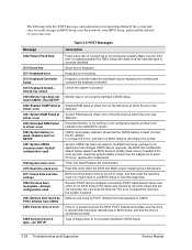
... type in BIOS Setup, and that the drive is dead-Replace and run BIOS Setup to modify these values if needed If the error persists, check the system battery Connect the AC adapter for reported problems If the system fails after you make changes in BIOS Setup 3-28 Troubleshooting and Diagnostics Service Manual The following table lists POST messages and explanations for at least 24 hours; Unlock key switch 0220 Monitor type does not match CMOS-Run SETUP...
... type in BIOS Setup, and that the drive is dead-Replace and run BIOS Setup to modify these values if needed If the error persists, check the system battery Connect the AC adapter for reported problems If the system fails after you make changes in BIOS Setup 3-28 Troubleshooting and Diagnostics Service Manual The following table lists POST messages and explanations for at least 24 hours; Unlock key switch 0220 Monitor type does not match CMOS-Run SETUP...
Maintenance and Service Guide
Page 122
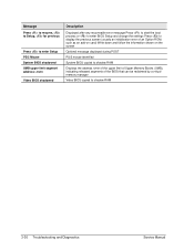
... to start the boot process or to enter BIOS Setup and change the settings Press to display the previous screen (usually an initialization error of an Option ROM, such as an add-on card) Write down and follow the information shown on the screen Optional message displayed during POST PS/2 mouse identified System BIOS copied to shadow RAM Displays the address nnnn of the upper limit of Upper Memory Blocks (UMB), indicating...
... to start the boot process or to enter BIOS Setup and change the settings Press to display the previous screen (usually an initialization error of an Option ROM, such as an add-on card) Write down and follow the information shown on the screen Optional message displayed during POST PS/2 mouse identified System BIOS copied to shadow RAM Displays the address nnnn of the upper limit of Upper Memory Blocks (UMB), indicating...
Maintenance and Service Guide
Page 127
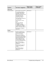
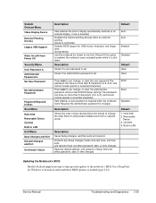
... Set User Password Set Administrator Password Password Required to Boot Boot Menu Hard Disk Removable Device CD/DVD Built-in LAN Exit Menu Save Changes and Exit Discard Changes and Exit Get Default Values Description Default Sets whether the built-in display automatically switches to an external display, if one is detected Disables the internal pointing devices when an external pointing device is connected Enables BIOS support for USB mouse, keyboard, and floppy drive during startup Lets the notebook be turned on via the LAN port If this option is enabled, the notebook uses increased power...
... Set User Password Set Administrator Password Password Required to Boot Boot Menu Hard Disk Removable Device CD/DVD Built-in LAN Exit Menu Save Changes and Exit Discard Changes and Exit Get Default Values Description Default Sets whether the built-in display automatically switches to an external display, if one is detected Disables the internal pointing devices when an external pointing device is connected Enables BIOS support for USB mouse, keyboard, and floppy drive during startup Lets the notebook be turned on via the LAN port If this option is enabled, the notebook uses increased power...


