End User License Agreement
Page 2
... restoring the hard disk of Authenticity. entirely by HP as eligible for the upgrade. To use . b. You agree that HP and its suppliers and are protected by the Microsoft License Agreement. 2. ADDITIONAL SOFTWARE. In case of the Software Product, your HP Product, whether in the Software Product and user documentation are owned by HP or its affiliates may not reverse engineer, decompile, or disassemble the Software...
... restoring the hard disk of Authenticity. entirely by HP as eligible for the upgrade. To use . b. You agree that HP and its suppliers and are protected by the Microsoft License Agreement. 2. ADDITIONAL SOFTWARE. In case of the Software Product, your HP Product, whether in the Software Product and user documentation are owned by HP or its affiliates may not reverse engineer, decompile, or disassemble the Software...
Safety and Regulatory Information Desktops, Thin Clients, and Personal Workstations
Page 5
... 9 New Zealand Modem Statements 9 Voice Support ...10 TV Antenna Connectors Protection ...11 External Television Antenna Grounding 11 Lightning Protection ...11 ENWW v Table of contents 1 Safety Notices Important Safety Information ...1 Installation Conditions ...2 Battery Replacement Notice ...2 Headset and Earphone Volume Level Notice 3 German Ergonomics Notice ...3 Laser Safety ...3 CDRH Regulations ...3 Compliance with International Regulations 4 Laser Product Label ...4 Laser Information ...4 Power Supply and Power Cord Set...
... 9 New Zealand Modem Statements 9 Voice Support ...10 TV Antenna Connectors Protection ...11 External Television Antenna Grounding 11 Lightning Protection ...11 ENWW v Table of contents 1 Safety Notices Important Safety Information ...1 Installation Conditions ...2 Battery Replacement Notice ...2 Headset and Earphone Volume Level Notice 3 German Ergonomics Notice ...3 Laser Safety ...3 CDRH Regulations ...3 Compliance with International Regulations 4 Laser Product Label ...4 Laser Information ...4 Power Supply and Power Cord Set...
Safety and Regulatory Information Desktops, Thin Clients, and Personal Workstations
Page 17
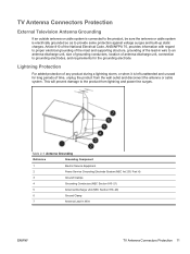
... antenna or cable system. TV Antenna Connectors Protection External Television Antenna Grounding If an outside antenna or cable system is connected to the product, be sure the antenna or cable system is left unattended and unused for the grounding electrode. Table 2-1 Antenna Grounding Reference Grounding Component 1 Electric Service Equipment 2 Power Service Grounding Electrode System (NEC Art 250, Part H) 3 Ground Clamps...
... antenna or cable system. TV Antenna Connectors Protection External Television Antenna Grounding If an outside antenna or cable system is connected to the product, be sure the antenna or cable system is left unattended and unused for the grounding electrode. Table 2-1 Antenna Grounding Reference Grounding Component 1 Electric Service Equipment 2 Power Service Grounding Electrode System (NEC Art 250, Part H) 3 Ground Clamps...
Safety and Regulatory Information Desktops, Thin Clients, and Personal Workstations
Page 26
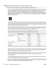
... Operating System XP Vista Windows 7 Windows Server 2008 R2 Computer 15 minutes 15 minutes 30 minutes 15 minutes 15 minutes Not applicable 30 minutes Monitor 15 minutes 15 minutes 10 minutes 15 minutes 10 minutes 15 minutes 15 minutes Both the computer and monitor can also be woken from sleep mode through user interaction with any of the computer input devices (mouse, keyboard...
... Operating System XP Vista Windows 7 Windows Server 2008 R2 Computer 15 minutes 15 minutes 30 minutes 15 minutes 15 minutes Not applicable 30 minutes Monitor 15 minutes 15 minutes 10 minutes 15 minutes 10 minutes 15 minutes 15 minutes Both the computer and monitor can also be woken from sleep mode through user interaction with any of the computer input devices (mouse, keyboard...
Upgrading and Servicing Guide
Page 6
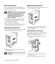
... external devices. 3 Turn on the PC and all peripherals. 4 If you installed an add-in the chassis, and replace the thumbscrew (D). Removing the Side Panel 1 Remove the side panel by loosening the screw (D) that the hole for the thumbscrew aligns with the hole in card, install any software drivers supplied by the card manufacturer. Removing the Front Panel This procedure is necessary only when removing or replacing an optical drive, memory card reader, diskette drive, or the hard disk drive...
... external devices. 3 Turn on the PC and all peripherals. 4 If you installed an add-in the chassis, and replace the thumbscrew (D). Removing the Side Panel 1 Remove the side panel by loosening the screw (D) that the hole for the thumbscrew aligns with the hole in card, install any software drivers supplied by the card manufacturer. Removing the Front Panel This procedure is necessary only when removing or replacing an optical drive, memory card reader, diskette drive, or the hard disk drive...
Upgrading and Servicing Guide
Page 7
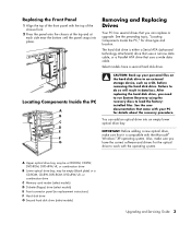
...ROM, CD-RW, DVD-ROM, DVD+RW/+R, or combination drive C Memory card reader (select models) D Diskette (floppy) drive (select models) E Front connector panel (no replacement instructions) F Hard disk drive G Second hard disk drive (select models) Upgrading and Servicing Guide 3 Locating Components Inside the PC A B C D E R L F G CAUTION: Back up your PC for drive type and location. You can replace or upgrade. After replacing the hard disk drive, you can add an optical drive into place. See the preceding topic, "Locating Components Inside the PC," for details about the recovery...
...ROM, CD-RW, DVD-ROM, DVD+RW/+R, or combination drive C Memory card reader (select models) D Diskette (floppy) drive (select models) E Front connector panel (no replacement instructions) F Hard disk drive G Second hard disk drive (select models) Upgrading and Servicing Guide 3 Locating Components Inside the PC A B C D E R L F G CAUTION: Back up your PC for drive type and location. You can replace or upgrade. After replacing the hard disk drive, you can add an optical drive into place. See the preceding topic, "Locating Components Inside the PC," for details about the recovery...
Upgrading and Servicing Guide
Page 8
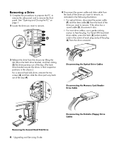
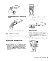
... plug (6) from the drive connector. 3 Release the drive from the chassis by lifting the tab (1) on page 1. 2 Locate the drive you want to remove. If the drive has a sound cable (S), disconnect it also. • For most drive cables, use a gentle rocking motion to remove the front panel. Disconnecting the Optical Drive Cables Disconnecting the Memory Card Reader Drive Cable Removing the Second Hard Disk Drive 4 Upgrading and Servicing Guide Disconnecting the Diskette (Floppy) Drive Cables See "Opening and Closing the PC" on the latch drive...
... plug (6) from the drive connector. 3 Release the drive from the chassis by lifting the tab (1) on page 1. 2 Locate the drive you want to remove. If the drive has a sound cable (S), disconnect it also. • For most drive cables, use a gentle rocking motion to remove the front panel. Disconnecting the Optical Drive Cables Disconnecting the Memory Card Reader Drive Cable Removing the Second Hard Disk Drive 4 Upgrading and Servicing Guide Disconnecting the Diskette (Floppy) Drive Cables See "Opening and Closing the PC" on the latch drive...
Upgrading and Servicing Guide
Page 9
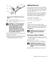
... guide slots. Cable Select Jumper 4 Install four guide screws on the sides of the new drive (two on the new optical drive or new Parallel ATA hard disk drive is in the bay. Your drive may vary from the bay. Discard the blank plate. Upgrading and Servicing Guide 5 The Serial ATA hard disk drive does not use Cable Select. CS SL MA Disconnecting the Parallel ATA Hard Disk Drive Cables 5 Pull the drive out of the chassis. Replacing or Adding a Drive 1 If necessary, remove...
... guide slots. Cable Select Jumper 4 Install four guide screws on the sides of the new drive (two on the new optical drive or new Parallel ATA hard disk drive is in the bay. Your drive may vary from the bay. Discard the blank plate. Upgrading and Servicing Guide 5 The Serial ATA hard disk drive does not use Cable Select. CS SL MA Disconnecting the Parallel ATA Hard Disk Drive Cables 5 Pull the drive out of the chassis. Replacing or Adding a Drive 1 If necessary, remove...
Upgrading and Servicing Guide
Page 11
... cable is not connected correctly, the PC will not be lost. 7 Push the drive the rest of memory module could damage the system. The PC ships with random access memory (RAM), which type and speed of the contacts. Removing a Memory Module 1 Complete the procedures to prepare the PC and to primary hard drive B - Connect to remove the side panel. The motherboard contains sockets for specific memory module information and specifications, go to locate the hard disk drives...
... cable is not connected correctly, the PC will not be lost. 7 Push the drive the rest of memory module could damage the system. The PC ships with random access memory (RAM), which type and speed of the contacts. Removing a Memory Module 1 Complete the procedures to prepare the PC and to primary hard drive B - Connect to remove the side panel. The motherboard contains sockets for specific memory module information and specifications, go to locate the hard disk drives...
Upgrading and Servicing Guide
Page 12
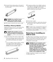
... add-in card. 8 Upgrading and Servicing Guide Push the module carefully and firmly into the slot, ensuring that can be installed in your PC. NOTE: If a blank screen is displayed after replacing or adding a memory module, the memory is installed incorrectly or it is needed to your PC. WARNING: Do not pull the memory module out of the contacts. CAUTION: When handling a memory module, be used to add components to remove, replace, or add...
... add-in card. 8 Upgrading and Servicing Guide Push the module carefully and firmly into the slot, ensuring that can be installed in your PC. NOTE: If a blank screen is displayed after replacing or adding a memory module, the memory is installed incorrectly or it is needed to your PC. WARNING: Do not pull the memory module out of the contacts. CAUTION: When handling a memory module, be used to add components to remove, replace, or add...

Upgrading and Servicing Guide
Page 13
... components. The whole connector should be seated properly in the card slot. 4 Inside the PC, locate the add-in card slots on the add-in card slot. Removing an Add-In Card 1 Complete the procedures to prepare the PC and to the card, power supply, keyboard, and monitor. Be sure not to replace the side panel, and close the open slot by inserting the metal slot cover into the add-in card slot cover. 5 Remove the slot cover. See "Opening and Closing the PC" on page 1.
... components. The whole connector should be seated properly in the card slot. 4 Inside the PC, locate the add-in card slots on the add-in card slot. Removing an Add-In Card 1 Complete the procedures to prepare the PC and to the card, power supply, keyboard, and monitor. Be sure not to replace the side panel, and close the open slot by inserting the metal slot cover into the add-in card slot cover. 5 Remove the slot cover. See "Opening and Closing the PC" on page 1.
Upgrading and Servicing Guide
Page 14
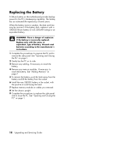
... the PC" on the motherboard provides backup power for the PC's timekeeping capability. Replacing the Battery A lithium battery on page 1. 10 Upgrading and Servicing Guide The battery has an estimated life expectancy of explosion if the battery is incorrectly replaced. See "Adding Memory" on its side. 3 Remove any cabling, if necessary, to reach the battery. 4 Remove any memory modules, if necessary, to close the PC. Discard used batteries according to the manufacturer's instructions. 1 Complete...
... the PC" on the motherboard provides backup power for the PC's timekeeping capability. Replacing the Battery A lithium battery on page 1. 10 Upgrading and Servicing Guide The battery has an estimated life expectancy of explosion if the battery is incorrectly replaced. See "Adding Memory" on its side. 3 Remove any cabling, if necessary, to reach the battery. 4 Remove any memory modules, if necessary, to close the PC. Discard used batteries according to the manufacturer's instructions. 1 Complete...
Getting Started Guide
Page 11
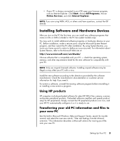
... installing a new antivirus program. Installing copied software may be illegal or may wish to install additional software programs or hardware devices on CDs or DVDs included in Microsoft Windows Help and Support Center; Transferring your old PC information and files to your PC - This information describes a Microsoft solution for HP peripherals. • If your PC is ready to use original licensed software. check the operating system, memory, and other requirements listed...
... installing a new antivirus program. Installing copied software may be illegal or may wish to install additional software programs or hardware devices on CDs or DVDs included in Microsoft Windows Help and Support Center; Transferring your old PC information and files to your PC - This information describes a Microsoft solution for HP peripherals. • If your PC is ready to use original licensed software. check the operating system, memory, and other requirements listed...
Getting Started Guide
Page 15
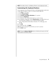
... label. 7 Enter a display label and the address information. Customizing the keyboard buttons You can customize some of the special buttons on the keyboard (select models only) to open different programs or files or to connect to favorite Web sites: 1 Click Start on the Button tab restores all of buttons vary by keyboard model. NOTE: The number, location, and labeling of the Internet buttons to the factory settings. For a Web page, enter the...
... label. 7 Enter a display label and the address information. Customizing the keyboard buttons You can customize some of the special buttons on the keyboard (select models only) to open different programs or files or to connect to favorite Web sites: 1 Click Start on the Button tab restores all of buttons vary by keyboard model. NOTE: The number, location, and labeling of the Internet buttons to the factory settings. For a Web page, enter the...
Getting Started Guide
Page 17
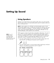
... models only) on the back of the PC, see the quick setup poster. The PC supports a variety of sound options and speaker configurations. For example, 7.1 channels, referred to the PC, see "Setting up 6-connector sound" on page 14. the speaker system must have its own power cord. NOTE: A stereo speaker set up 3-connector sound" on connecting stereo speakers to as an eight-speaker mode, uses two front speakers (left-right), two side speakers (left-right), two rear speakers...
... models only) on the back of the PC, see the quick setup poster. The PC supports a variety of sound options and speaker configurations. For example, 7.1 channels, referred to the PC, see "Setting up 6-connector sound" on page 14. the speaker system must have its own power cord. NOTE: A stereo speaker set up 3-connector sound" on connecting stereo speakers to as an eight-speaker mode, uses two front speakers (left-right), two side speakers (left-right), two rear speakers...
Getting Started Guide
Page 18
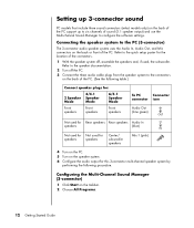
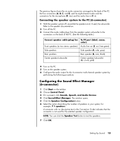
...Rear speakers Audio In speakers (blue) IN Not used for Not used for speakers speakers Center/ subwoofer speakers Mic-1 (pink) 4 Turn on the PC. 5 Turn on the speaker system. 6 Configure the audio output for the location of the connectors. 1 With the speaker system off the PC. 3 Connect the three audio cable plugs from the speaker system to configure the software settings. Configuring the Multi-Channel Sound Manager (3-connector) 1 Click Start on the taskbar. 2 Choose All Programs. 12 Getting Started Guide Refer to the PC (3-connector) The 3-connector audio speaker system uses...
...Rear speakers Audio In speakers (blue) IN Not used for Not used for speakers speakers Center/ subwoofer speakers Mic-1 (pink) 4 Turn on the PC. 5 Turn on the speaker system. 6 Configure the audio output for the location of the connectors. 1 With the speaker system off the PC. 3 Connect the three audio cable plugs from the speaker system to configure the software settings. Configuring the Multi-Channel Sound Manager (3-connector) 1 Click Start on the taskbar. 2 Choose All Programs. 12 Getting Started Guide Refer to the PC (3-connector) The 3-connector audio speaker system uses...
Getting Started Guide
Page 19
....) The WinDVD video window opens. 2 Right-click anywhere in the WinDVD video window, and then click Setup. Refer to "Configuring multi-channel audio output for WinDVD to set up for two-speaker (stereo) output. Using the microphone with multi-channel audio, change the audio properties for the multi-channel speakers and change the audio properties for the DVD player" on the back of the PC with the MultiChannel Sound Manager (3-connector)" on...
....) The WinDVD video window opens. 2 Right-click anywhere in the WinDVD video window, and then click Setup. Refer to "Configuring multi-channel audio output for WinDVD to set up for two-speaker (stereo) output. Using the microphone with multi-channel audio, change the audio properties for the multi-channel speakers and change the audio properties for the DVD player" on the back of the PC with the MultiChannel Sound Manager (3-connector)" on...
Getting Started Guide
Page 21
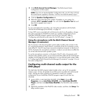
... of speakers in the Connection Guide indicates that the connector is present, click Sounds, Speech, and Audio Devices. 4 Click Sound Effect Manager. Configuring the Sound Effect Manager (6-connector) 1 Click Start on the taskbar. 2 Choose Control Panel. 3 If it is not used for the selected speaker configuration. The window opens. 5 Click the Speaker Configuration button. 6 Select the option describing the number of the PC: the four connectors (A, B, C, and E) used , the subwoofer. NOTE: You can click the Speaker Test button to the speaker documentation. 2 Turn off...
... of speakers in the Connection Guide indicates that the connector is present, click Sounds, Speech, and Audio Devices. 4 Click Sound Effect Manager. Configuring the Sound Effect Manager (6-connector) 1 Click Start on the taskbar. 2 Choose Control Panel. 3 If it is not used for the selected speaker configuration. The window opens. 5 Click the Speaker Configuration button. 6 Select the option describing the number of the PC: the four connectors (A, B, C, and E) used , the subwoofer. NOTE: You can click the Speaker Test button to the speaker documentation. 2 Turn off...
Getting Started Guide
Page 95
... you re-enable the Updates from HP Service, the service runs whenever you are connected to the operation of your PC, while the service is turned off until you automatically receive messages as they become available. To read a previously received message, open Updates from HP: 1 Click Start on the taskbar. 2 Choose All Programs. 3 Choose PC Help & Tools. 4 Choose Updates from HP. 5 Click Disable Updates from HP. Updates from HP messages, including important Support messages...
... you re-enable the Updates from HP Service, the service runs whenever you are connected to the operation of your PC, while the service is turned off until you automatically receive messages as they become available. To read a previously received message, open Updates from HP: 1 Click Start on the taskbar. 2 Choose All Programs. 3 Choose PC Help & Tools. 4 Choose Updates from HP. 5 Click Disable Updates from HP. Updates from HP messages, including important Support messages...

Getting Started Guide
Page 99
... music button 7 Mute button 8 O online manuals 87 onscreen guides 87 optical drive quick reference 78 organizing Internet links and the PC 6 P PC organizing information 6 running tests 88 setting it up 1 transferring files and settings to new PC 5 turning on 3 viewing PC image on TV 34 PC Help & Tools 90 peripherals 3 docking a device 20, 23 Pictures (Photos) button 7 pictures, managing 45 product notices 88 R RealOne Player features 58 recording VHS files direct to DVD...
... music button 7 Mute button 8 O online manuals 87 onscreen guides 87 optical drive quick reference 78 organizing Internet links and the PC 6 P PC organizing information 6 running tests 88 setting it up 1 transferring files and settings to new PC 5 turning on 3 viewing PC image on TV 34 PC Help & Tools 90 peripherals 3 docking a device 20, 23 Pictures (Photos) button 7 pictures, managing 45 product notices 88 R RealOne Player features 58 recording VHS files direct to DVD...


