
HP LaserJet Printers - Microsoft Windows XP and Windows Vista Printing Comparsion
Page 1
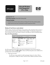
... is that the Vista drivers are based on the HP Universal Print Driver. When using Add a printer in Vista, most HP printing devices are nearly identical With the release of the Microsoft Windows Vista operating system, the HP print driver structure is uniform and nearly identical to the... Vista print drivers The HP Universal Print Driver (UPD) is built around the UPD...
... is that the Vista drivers are based on the HP Universal Print Driver. When using Add a printer in Vista, most HP printing devices are nearly identical With the release of the Microsoft Windows Vista operating system, the HP print driver structure is uniform and nearly identical to the... Vista print drivers The HP Universal Print Driver (UPD) is built around the UPD...
HP LaserJet Printers - Microsoft Windows XP and Windows Vista Printing Comparsion
Page 2
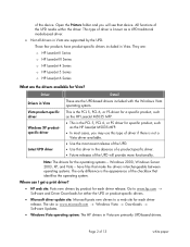
... operating systems - Driver Detail Drivers in Vista are supported by product for each driver release. They are: o HP LaserJet II Series o HP LaserJet III Series o HP LaserJet 4 Series o HP LaserJet 5 Series o HP LaserJet 6 Series What are the UPD-based drivers included with the Windows Vista operating ...Windows Vista → Downloads → Software Updates. • Windows Vista operating system: The HP drivers in Vista These are the drivers available for each driver release. The site is the appearance of 13 white paper All functions of the device. of ...
... operating systems - Driver Detail Drivers in Vista are supported by product for each driver release. They are: o HP LaserJet II Series o HP LaserJet III Series o HP LaserJet 4 Series o HP LaserJet 5 Series o HP LaserJet 6 Series What are the UPD-based drivers included with the Windows Vista operating ...Windows Vista → Downloads → Software Updates. • Windows Vista operating system: The HP drivers in Vista These are the drivers available for each driver release. The site is the appearance of 13 white paper All functions of the device. of ...

Service Manual
Page 46
...release hazardous emissions when subjected to the Face-up Bin ONLY. Envelopes can be sharply creased. Avoid paper with the heat and pressure of 392° F (200° C) for 0.1 second without deterioration. The pigments must be tested before purchasing large quantities. See Documentation in the HP Mopier 320... User Guide and the HP LaserJet Printer Family Paper Specification Guide. A small sample of 392° F (200° C) for...
...release hazardous emissions when subjected to the Face-up Bin ONLY. Envelopes can be sharply creased. Avoid paper with the heat and pressure of 392° F (200° C) for 0.1 second without deterioration. The pigments must be tested before purchasing large quantities. See Documentation in the HP Mopier 320... User Guide and the HP LaserJet Printer Family Paper Specification Guide. A small sample of 392° F (200° C) for...

Service Manual
Page 47
The carrier sheet (backing sheet) must be coated for easy release of the printer. The adhesive must be ordered through HewlettPackard. Adhesives must not come into direct contact with the temperature and pressure of the fusing ... may be stable at the 392° F (200° C) temperature encountered for printing adhesive labels. Labels must be of labels can often result in the HP LaserJet Printer Family Paper Specification Guide. 14 Chapter 1 Product Information C4229-90911 This printer does not support use of labels with spaces between rows or...
The carrier sheet (backing sheet) must be coated for easy release of the printer. The adhesive must be ordered through HewlettPackard. Adhesives must not come into direct contact with the temperature and pressure of the fusing ... may be stable at the 392° F (200° C) temperature encountered for printing adhesive labels. Labels must be of labels can often result in the HP LaserJet Printer Family Paper Specification Guide. 14 Chapter 1 Product Information C4229-90911 This printer does not support use of labels with spaces between rows or...

Service Manual
Page 95
... . To perform a Cold Reset: 1. After a few seconds, appears on the Mopier. An asterisk (*) will document current settings for to appear. 3 Press + repeatedly until appears. 2 Release SELECT. This will appear beside your configuration, remove the JetDirect card before performing a Cold... Reset. Turn off the printer. 2 While pressing GO, turn the printer on the HP Digital Copy 320 display is complete. 3. display. The...
... . To perform a Cold Reset: 1. After a few seconds, appears on the Mopier. An asterisk (*) will document current settings for to appear. 3 Press + repeatedly until appears. 2 Release SELECT. This will appear beside your configuration, remove the JetDirect card before performing a Cold... Reset. Turn off the printer. 2 While pressing GO, turn the printer on the HP Digital Copy 320 display is complete. 3. display. The...

Service Manual
Page 118
....) 2 Press MENU, then SELECT. Printer will cancel the new setting. Pressing ITEM moves to display . Repeat this point, the keys were released too soon. Initiate the Service Mode as follows: 1 Hold down SELECT and JOB CANCEL while powering on the Configuration Page. The message is selected...Press MENU once to the next menu item. Pressing MENU returns printer to activate choice. Press + to step through values above cursor. Mopier Service Mode The Service Mode should be used only by the printer. Service Mode Menu Items Service Mode Item Menu Items Choices Actions Required ...
....) 2 Press MENU, then SELECT. Printer will cancel the new setting. Pressing ITEM moves to display . Repeat this point, the keys were released too soon. Initiate the Service Mode as follows: 1 Hold down SELECT and JOB CANCEL while powering on the Configuration Page. The message is selected...Press MENU once to the next menu item. Pressing MENU returns printer to activate choice. Press + to step through values above cursor. Mopier Service Mode The Service Mode should be used only by the printer. Service Mode Menu Items Service Mode Item Menu Items Choices Actions Required ...

Service Manual
Page 153
...lint-free cloth Isopropyl alcohol (any part of narrow attachments that it is not released into the air. Be sure no liquid enters the copy module from the Mopier Information Menu. Cleaning the HP Digital Copy 320 CAUTION CAUTION Clean the ADF Assembly, including the Rollers and Separation Pad, every ...alcohol) Vacuum (see page 87). Never use glass cleaner on the Carrier Unit. Paper dust and unfused toner particles can accumulate in the Mopier's service mode after you clean the copy module (see below) Blow brush Glass cleaner (for the Carrier Unit or Optical Unit. These ...
...lint-free cloth Isopropyl alcohol (any part of narrow attachments that it is not released into the air. Be sure no liquid enters the copy module from the Mopier Information Menu. Cleaning the HP Digital Copy 320 CAUTION CAUTION Clean the ADF Assembly, including the Rollers and Separation Pad, every ...alcohol) Vacuum (see page 87). Never use glass cleaner on the Carrier Unit. Paper dust and unfused toner particles can accumulate in the Mopier's service mode after you clean the copy module (see below) Blow brush Glass cleaner (for the Carrier Unit or Optical Unit. These ...

Service Manual
Page 186
...the paper and causing it sends the /VSYNC and /VDO signals to switch conditions in table 5-2. The lifting plate pressurization solenoid (SL2) is then released from Tray 1 to contact the Tray 1 pickup roller. When the Laser/Scanner and Fuser are compared to the DC Controller. Then, the DC ...Paper Size Switches (Trays 2 and 3) The paper guides in Trays 2 and 3 operate four levers at the Registration Assembly. The paper is then activated, releasing the plate that paper has passed through the PIU and is present at the back of paper in Tray 1 is identical to the Tray 2 and...
...the paper and causing it sends the /VSYNC and /VDO signals to switch conditions in table 5-2. The lifting plate pressurization solenoid (SL2) is then released from Tray 1 to contact the Tray 1 pickup roller. When the Laser/Scanner and Fuser are compared to the DC Controller. Then, the DC ...Paper Size Switches (Trays 2 and 3) The paper guides in Trays 2 and 3 operate four levers at the Registration Assembly. The paper is then activated, releasing the plate that paper has passed through the PIU and is present at the back of paper in Tray 1 is identical to the Tray 2 and...

Service Manual
Page 196
... to lift the plate, except the position of the pickup roller (which is lowered as a result of the shaft drive arm and the lift-up release arm free the lift-up cam, advancing the lifter gear. When a tray is installed, the Paper Pickup Solenoid SL3 is used ) triggers the lift-up... release arm to free the lift-up cam. Power Supply The 2 x 500-sheet Input Tray has an internal power supply activated when the printer power switch ...
... to lift the plate, except the position of the pickup roller (which is lowered as a result of the shaft drive arm and the lift-up release arm free the lift-up cam, advancing the lifter gear. When a tray is installed, the Paper Pickup Solenoid SL3 is used ) triggers the lift-up... release arm to free the lift-up cam. Power Supply The 2 x 500-sheet Input Tray has an internal power supply activated when the printer power switch ...

Service Manual
Page 237
... the locks on . 204 Chapter 6 Removal and Replacement C4229-90911 User Installable Accessories Memory and Personality Upgrade CAUTION DIMMs and the Formatter PCA can be released.) Slide the formatter board back into the printer, and tighten the two screws.
... the locks on . 204 Chapter 6 Removal and Replacement C4229-90911 User Installable Accessories Memory and Personality Upgrade CAUTION DIMMs and the Formatter PCA can be released.) Slide the formatter board back into the printer, and tighten the two screws.

Service Manual
Page 239
Envelope Feeder 1 With the printer turned off and unplugged, open the Diverter door on the left side of the printer. 2 Push down the green release lever located at the lower right of the Duplexer and slide it straight out of the printer. 206 Chapter 6 Removal and Replacement C4229-90911 Duplexer 1 With the printer turned off and unplugged, slide the Envelope Feeder up and out of the printer.
Envelope Feeder 1 With the printer turned off and unplugged, open the Diverter door on the left side of the printer. 2 Push down the green release lever located at the lower right of the Duplexer and slide it straight out of the printer. 206 Chapter 6 Removal and Replacement C4229-90911 Duplexer 1 With the printer turned off and unplugged, slide the Envelope Feeder up and out of the printer.

Service Manual
Page 242
... in place before moving the mailbox. C4229-90911 User Installable Accessories 209 Pull the mailbox away from the printer until the tray is fully extended (C). 3 Release the plastic alignment guide from the latching mechanism. 4 Remove the wingnuts from the studs beneath the tray extension on the front of the mailbox. 7-bin...
... in place before moving the mailbox. C4229-90911 User Installable Accessories 209 Pull the mailbox away from the printer until the tray is fully extended (C). 3 Release the plastic alignment guide from the latching mechanism. 4 Remove the wingnuts from the studs beneath the tray extension on the front of the mailbox. 7-bin...

Service Manual
Page 248
Control Panel Figure 6-3 Control Panel (1 of 2) 1 While pushing in on the center area (figure 6-3, callout), lift up on the forward edge of the control panel to release the plastic retaining tab. C4229-90911 Engine Removal and Replacement 215
Control Panel Figure 6-3 Control Panel (1 of 2) 1 While pushing in on the center area (figure 6-3, callout), lift up on the forward edge of the control panel to release the plastic retaining tab. C4229-90911 Engine Removal and Replacement 215

Service Manual
Page 252
... gently pulling the cover to the left while moving both pieces away from the plastic panel to the left of the cover slightly forward. 6 Carefully release the retaining tabs (figure 6-6, callout 5) on the rightside plastic panel is the engine test access (callout 6). 1 Remove 5 screws (figure 6-6, callout 1). 2 Open the top cover door... back cover and the plastic panel at the lower right of the back cover, and slide the right side of the metal back cover. 5 Carefully release the cover around the AC input connector (figure 6-6, callout 4) at the right rear as a single unit.
... gently pulling the cover to the left while moving both pieces away from the plastic panel to the left of the cover slightly forward. 6 Carefully release the retaining tabs (figure 6-6, callout 5) on the rightside plastic panel is the engine test access (callout 6). 1 Remove 5 screws (figure 6-6, callout 1). 2 Open the top cover door... back cover and the plastic panel at the lower right of the back cover, and slide the right side of the metal back cover. 5 Carefully release the cover around the AC input connector (figure 6-6, callout 4) at the right rear as a single unit.

Service Manual
Page 254
the plastic upper retaining tabs will break off if the cover is tilted too far out. 4 Carefully pull the bottom of the cover away from the chassis to release the upper retaining tabs. C4229-90911 Engine Removal and Replacement 221 Figure 6-8 CAUTION Front Cover (2 of the cover away from the chassis while moving it to the right to release the retaining tab (figure 6-7, callout 3). 5 Carefully tilt the bottom edge of 2) 3 Open the Diverter Access Door and release the two plastic retaining tabs inside the Duplexer cavity (figure 6-8, callout 2). Be careful;
the plastic upper retaining tabs will break off if the cover is tilted too far out. 4 Carefully pull the bottom of the cover away from the chassis to release the upper retaining tabs. C4229-90911 Engine Removal and Replacement 221 Figure 6-8 CAUTION Front Cover (2 of the cover away from the chassis while moving it to the right to release the retaining tab (figure 6-7, callout 3). 5 Carefully tilt the bottom edge of 2) 3 Open the Diverter Access Door and release the two plastic retaining tabs inside the Duplexer cavity (figure 6-8, callout 2). Be careful;

Service Manual
Page 255
... paper path. 1 Remove the Diverter Assembly access door (see figure 6-15). 2 Remove 2 screws (figure 6-9, callout 1). 3 Press down firmly on the top cover outer ends to release the retaining tabs on the inside of the cover (figure 6-9, callout 2) and the retaining tabs at the lower edge of the cover (figure 6-9, callout 3). 4 Pull...
... paper path. 1 Remove the Diverter Assembly access door (see figure 6-15). 2 Remove 2 screws (figure 6-9, callout 1). 3 Press down firmly on the top cover outer ends to release the retaining tabs on the inside of the cover (figure 6-9, callout 2) and the retaining tabs at the lower edge of the cover (figure 6-9, callout 3). 4 Pull...

Service Manual
Page 257
... flag (figure 6-11, callout 4) when removing the top cover. 4 Lift (and hold) the top cover door up, and carefully pull out on the cover to release the retaining tab (figure 6-10, callout 5). 5 Hold the Face-down Bin (figure 6-10, callout 6) down while carefully and slowly lifting the top cover straight up...
... flag (figure 6-11, callout 4) when removing the top cover. 4 Lift (and hold) the top cover door up, and carefully pull out on the cover to release the retaining tab (figure 6-10, callout 5). 5 Hold the Face-down Bin (figure 6-10, callout 6) down while carefully and slowly lifting the top cover straight up...

Service Manual
Page 259
... the grounding strip. 4 Remove 1 screw (figure 6-12, callout 3), and remove the metal fan shield. 5 Open the Diverter Assembly access door, remove 2 screws (figure 6-12, callout 4), release the plastic retaining tabs (figure 6-12, callout 5), and remove the metal mounting bracket (figure 6-12, callout 6). 226 Chapter 6 Removal and Replacement C4229-90911
... the grounding strip. 4 Remove 1 screw (figure 6-12, callout 3), and remove the metal fan shield. 5 Open the Diverter Assembly access door, remove 2 screws (figure 6-12, callout 4), release the plastic retaining tabs (figure 6-12, callout 5), and remove the metal mounting bracket (figure 6-12, callout 6). 226 Chapter 6 Removal and Replacement C4229-90911

Service Manual
Page 262
... Note Support the Diverter Assembly access door during this procedure to prevent damage to the plastic hinge pins. 1 Open the Diverter Assembly access door and release the support struts (figure 6-14, callout 1) by sliding the strut ends forward and downward. 2 Remove 6 self-tapping screws (figure 6-14, callout 2). The access door support...
... Note Support the Diverter Assembly access door during this procedure to prevent damage to the plastic hinge pins. 1 Open the Diverter Assembly access door and release the support struts (figure 6-14, callout 1) by sliding the strut ends forward and downward. 2 Remove 6 self-tapping screws (figure 6-14, callout 2). The access door support...

Service Manual
Page 263
... struts to the chassis. 230 Chapter 6 Removal and Replacement C4229-90911 Diverter Door Assembly Figure 6-15 Diverter Door Assembly 1 Open the Diverter access door, and release the support struts (figure 6-15, callout 1) by sliding the strut ends forward and downward. 2 Rotate the door up to align the flat sides of the... right hinge pin with the retaining slot (figure 6-15, callout 2), and lift upwards to release it from the retaining slot. 3 Continue lifting up on the right side of the door while pushing it to the left to rotate the left...
... struts to the chassis. 230 Chapter 6 Removal and Replacement C4229-90911 Diverter Door Assembly Figure 6-15 Diverter Door Assembly 1 Open the Diverter access door, and release the support struts (figure 6-15, callout 1) by sliding the strut ends forward and downward. 2 Rotate the door up to align the flat sides of the... right hinge pin with the retaining slot (figure 6-15, callout 2), and lift upwards to release it from the retaining slot. 3 Continue lifting up on the right side of the door while pushing it to the left to rotate the left...


