
HP LaserJet M2727 MFP Series - User Guide
Page 243
...manner that this product must not be obtained by handing it is your responsibility to dispose of your waste equipment by contacting the HP Web site at the time of disposal will help to conserve natural resources and ensure that it over to www..., toner) can be disposed of your waste equipment at www.hp.com/go to a designated collection point for recycling, please contact your local city office, your other household waste. HP LaserJet M2727 Type Weight Location User-removable Carbon monofluoride lithium 0.8 g On formatter board No For recycling information, you can go /msds or ...
...manner that this product must not be obtained by handing it is your responsibility to dispose of your waste equipment by contacting the HP Web site at the time of disposal will help to conserve natural resources and ensure that it over to www..., toner) can be disposed of your waste equipment at www.hp.com/go to a designated collection point for recycling, please contact your local city office, your other household waste. HP LaserJet M2727 Type Weight Location User-removable Carbon monofluoride lithium 0.8 g On formatter board No For recycling information, you can go /msds or ...

Service Manual
Page 8
... panel ...119 Internal assemblies ...122 Convenience-stapler assembly (HP LaserJet M2727nfs only 122 Convenience-stapler power supply (HP LaserJet M2727nfs only 124 Convenience-stapler AC inlet cable (HP LaserJet M2727nfs only 126 Convenience-stapler power supply bracket and strap (HP LaserJet M2727nfs only) ..... 127 Speaker ...128 Power-switch PCA ...130 Formatter ...132 Duplex assembly ...135 Laser/scanner (print engine...
... panel ...119 Internal assemblies ...122 Convenience-stapler assembly (HP LaserJet M2727nfs only 122 Convenience-stapler power supply (HP LaserJet M2727nfs only 124 Convenience-stapler AC inlet cable (HP LaserJet M2727nfs only 126 Convenience-stapler power supply bracket and strap (HP LaserJet M2727nfs only) ..... 127 Speaker ...128 Power-switch PCA ...130 Formatter ...132 Duplex assembly ...135 Laser/scanner (print engine...

Service Manual
Page 11
Supplementary documentation and support 257 Problem-solve diagrams ...259 Repetitive image defects 259 Interface connectors ...260 Formatter connectors ...260 Fax card ...261 Solenoids ...262 Switches and sensors ...263 Rollers and pads ...264 PCAs (base... ...270 Types of screws ...271 Scanner and ADF assemblies ...272 Scanner components ...274 ADF components ...276 Convenience stapler components (HP LaserJet M2727nfs only 278 Formatter, fax card, HP jewel, and nameplate 280 External covers and panels ...282 Cartridge door assembly ...284 Internal components (1 of 4) ...286 Internal ...
Supplementary documentation and support 257 Problem-solve diagrams ...259 Repetitive image defects 259 Interface connectors ...260 Formatter connectors ...260 Fax card ...261 Solenoids ...262 Switches and sensors ...263 Rollers and pads ...264 PCAs (base... ...270 Types of screws ...271 Scanner and ADF assemblies ...272 Scanner components ...274 ADF components ...276 Convenience stapler components (HP LaserJet M2727nfs only 278 Formatter, fax card, HP jewel, and nameplate 280 External covers and panels ...282 Cartridge door assembly ...284 Internal components (1 of 4) ...286 Internal ...

Service Manual
Page 13
List of tables Table 1-1 Product guides ...2 Table 1-2 Supported printer drivers ...9 Table 1-3 Supported paper and print media sizes 16 Table 1-4 Supported envelopes and postcards 17 Table 1-5 ADF ...17 Table 4-1 Sequence of operation ...70 ... ...257 Table 7-6 Getting started guide ...258 Table 7-7 Technical support Web sites ...258 Table 7-8 Repetitive image defects ...259 Table 7-9 Interface connectors ...260 Table 7-10 Formatter connectors ...260 Table 7-11 Fax card ...261 Table 7-12 Solenoids ...262 Table 7-13 Switches and sensors ...263 Table 7-14 Rollers and pads ...264 Table 7-15...
List of tables Table 1-1 Product guides ...2 Table 1-2 Supported printer drivers ...9 Table 1-3 Supported paper and print media sizes 16 Table 1-4 Supported envelopes and postcards 17 Table 1-5 ADF ...17 Table 4-1 Sequence of operation ...70 ... ...257 Table 7-6 Getting started guide ...258 Table 7-7 Technical support Web sites ...258 Table 7-8 Repetitive image defects ...259 Table 7-9 Interface connectors ...260 Table 7-10 Formatter connectors ...260 Table 7-11 Fax card ...261 Table 7-12 Solenoids ...262 Table 7-13 Switches and sensors ...263 Table 7-14 Rollers and pads ...264 Table 7-15...

Service Manual
Page 14
Table 7-21 Convenience stapler components (HP LaserJet M2727nfs only 279 Table 7-22 Formatter, Fax card, HP jewel, and nameplate 281 Table 7-23 External covers and panels ...283 Table 7-24 Cartridge door assembly ...285 Table 7-25 Internal components (1 of 4) ...287 Table 7-26 ...
Table 7-21 Convenience stapler components (HP LaserJet M2727nfs only 279 Table 7-22 Formatter, Fax card, HP jewel, and nameplate 281 Table 7-23 External covers and panels ...283 Table 7-24 Cartridge door assembly ...285 Table 7-25 Internal components (1 of 4) ...287 Table 7-26 ...

Service Manual
Page 17
... 2) ...128 Remove the speaker (2 of 2) ...129 Remove the power-switch PCA (HP LaserJet M2727nfs shown 130 Remove the power-switch PCA mounting bracket 131 Remove the formatter (1 of 5) ...132 Remove the formatter (2 of 5) ...133 Install formatter protective sheet 133 Remove the formatter (3 of 4) ...134 Remove the formatter (4 of 4) ...134 Remove the duplex assembly (1 of 2 135 Remove the...
... 2) ...128 Remove the speaker (2 of 2) ...129 Remove the power-switch PCA (HP LaserJet M2727nfs shown 130 Remove the power-switch PCA mounting bracket 131 Remove the formatter (1 of 5) ...132 Remove the formatter (2 of 5) ...133 Install formatter protective sheet 133 Remove the formatter (3 of 4) ...134 Remove the formatter (4 of 4) ...134 Remove the duplex assembly (1 of 2 135 Remove the...

Service Manual
Page 18
...connection points (right side 233 Figure 6-3 Print-cartridge high-voltage connection points (left side 234 Figure 7-1 Interface connectors ...260 Figure 7-2 Formatter connectors ...260 Figure 7-3 Fax card connectors ...261 Figure 7-4 Solenoids ...262 Figure 7-5 Switches and sensors ...263 Figure 7-6 Rollers and ...Figure 7-13 Scanner assemblies ...274 Figure 7-14 ADF components ...276 Figure 7-15 Convenience stapler components (HP LaserJet M2727nfs only 278 Figure 7-16 Formatter, fax card, HP jewel, and nameplate 280 Figure 7-17 External covers and panels ...282 Figure 7-18 Cartridge door ...
...connection points (right side 233 Figure 6-3 Print-cartridge high-voltage connection points (left side 234 Figure 7-1 Interface connectors ...260 Figure 7-2 Formatter connectors ...260 Figure 7-3 Fax card connectors ...261 Figure 7-4 Solenoids ...262 Figure 7-5 Switches and sensors ...263 Figure 7-6 Rollers and ...Figure 7-13 Scanner assemblies ...274 Figure 7-14 ADF components ...276 Figure 7-15 Convenience stapler components (HP LaserJet M2727nfs only 278 Figure 7-16 Formatter, fax card, HP jewel, and nameplate 280 Figure 7-17 External covers and panels ...282 Figure 7-18 Cartridge door ...

Service Manual
Page 54
...: Lithium carbon monofluoride (solid button cell) Approximately .1 gram On formatter PC board (one battery per product) No 36 Chapter 3 Maintenance ENWW The remaining materials are used cartridges and supplies, HP encourages the use of used to EN12281:2002. For more environmentally ...340-2445 or visit the HP Web site at www.hp.com/support/ ljpaperguide. Non-U.S. More than 10 million HP LaserJet print cartridges were recycled globally in an environmentally responsible manner. returns Non-U.S. This product is supplied in the HP LaserJet Printer Family Print Media Guide,...
...: Lithium carbon monofluoride (solid button cell) Approximately .1 gram On formatter PC board (one battery per product) No 36 Chapter 3 Maintenance ENWW The remaining materials are used cartridges and supplies, HP encourages the use of used to EN12281:2002. For more environmentally ...340-2445 or visit the HP Web site at www.hp.com/support/ ljpaperguide. Non-U.S. More than 10 million HP LaserJet print cartridges were recycled globally in an environmentally responsible manner. returns Non-U.S. This product is supplied in the HP LaserJet Printer Family Print Media Guide,...
Service Manual
Page 88
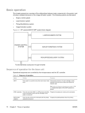
... the pickup Prepares the photosensitive drum for printing solenoid is turned on 70 Chapter 4 Theory of the image-formation system. clears drive potential from the formatter or the power is turned off INTR (initial rotation) From the time of the print command until the end of the main-motor initial Detects... the base unit Operational sequences are discussed: ● Engine control system ● Laser/scanner system ● Pickup/feed/delivery system ● Image-formation system Figure 4-1 HP LaserJet M2727 MFP system block diagram Sequence of a print cartridge;
... the pickup Prepares the photosensitive drum for printing solenoid is turned on 70 Chapter 4 Theory of the image-formation system. clears drive potential from the formatter or the power is turned off INTR (initial rotation) From the time of the print command until the end of the main-motor initial Detects... the base unit Operational sequences are discussed: ● Engine control system ● Laser/scanner system ● Pickup/feed/delivery system ● Image-formation system Figure 4-1 HP LaserJet M2727 MFP system block diagram Sequence of a print cartridge;

Service Manual
Page 89
... (last rotation) From the end of a print job After LSTR, the product either returns to STBY or, if another print command was sent from the formatter, enters INTR. Table 4-1 Sequence of operation (continued) Name Timing Purpose PRINT From the end of the INTR period until the primary high-voltage is turned...
... (last rotation) From the end of a print job After LSTR, the product either returns to STBY or, if another print command was sent from the formatter, enters INTR. Table 4-1 Sequence of operation (continued) Name Timing Purpose PRINT From the end of the INTR period until the primary high-voltage is turned...

Service Manual
Page 90
... being used , the scanner module advances to the next raster line. The image data is collected in the ADF to the next raster line. The formatter then handles the image data, outputting it as a fax , or directing it through the lens to the CCD. Scanner functions The scanner uses a light ...about the document and transform that into an image file. The mirrors direct the light through the Fax Card as a copy, sending it to the formatter. Scanner and ADF functions and operation The following sections describe how the document scanner and the automatic document feeder (ADF) function.
... being used , the scanner module advances to the next raster line. The image data is collected in the ADF to the next raster line. The formatter then handles the image data, outputting it as a fax , or directing it through the lens to the CCD. Scanner functions The scanner uses a light ...about the document and transform that into an image file. The mirrors direct the light through the Fax Card as a copy, sending it to the formatter. Scanner and ADF functions and operation The following sections describe how the document scanner and the automatic document feeder (ADF) function.

Service Manual
Page 96
It drives the laser/scanner system, the image-formation system, and the pickup/feed/ delivery system. The engine control system contains the following components: ● Formatter ● High-voltage PCA Figure 4-5 Engine control system 78 Chapter 4 Theory of the product functions, according to commands sent from the formatter. Engine control system The engine control system coordinates all of operation ENWW
It drives the laser/scanner system, the image-formation system, and the pickup/feed/ delivery system. The engine control system contains the following components: ● Formatter ● High-voltage PCA Figure 4-5 Engine control system 78 Chapter 4 Theory of the product functions, according to commands sent from the formatter. Engine control system The engine control system coordinates all of operation ENWW

Service Manual
Page 98
Figure 4-7 Laser/scanner system 80 Chapter 4 Theory of operation ENWW Laser/scanner system The laser/scanner system receives video signals from the DC controller and the formatter, and converts the signals into latent images on the photosensitive drum.
Figure 4-7 Laser/scanner system 80 Chapter 4 Theory of operation ENWW Laser/scanner system The laser/scanner system receives video signals from the DC controller and the formatter, and converts the signals into latent images on the photosensitive drum.

Service Manual
Page 99
... reach or pass each sensor within a specified time period, the DC controller determines that a jam has occurred and alerts the formatter. Three media-detection sensors detect media as it passes through the printer. The following components are identified in Figure 4-8 Pickup/feed/delivery system on page 82: ● M1, main motor ●...
... reach or pass each sensor within a specified time period, the DC controller determines that a jam has occurred and alerts the formatter. Three media-detection sensors detect media as it passes through the printer. The following components are identified in Figure 4-8 Pickup/feed/delivery system on page 82: ● M1, main motor ●...

Service Manual
Page 107
... of the fax card is compliant with the crowbar for fax transmissions. The fax subsystem The formatter, fax card, firmware, and software all of the formatter (SELV [secondary extra-low voltage]). ENWW Fax functions and operation 89 The breakdown voltage rating of... formatter and fax card, along with a phone line). The designs of high-voltage-barrier critical components (transformer and relay). Telephone over-voltage events can also improve your VoIP provider. This safety isolation provides both customer safety and product reliability in the HP LaserJet M2727 ...
... of the fax card is compliant with the crowbar for fax transmissions. The fax subsystem The formatter, fax card, firmware, and software all of the formatter (SELV [secondary extra-low voltage]). ENWW Fax functions and operation 89 The breakdown voltage rating of... formatter and fax card, along with a phone line). The designs of high-voltage-barrier critical components (transformer and relay). Telephone over-voltage events can also improve your VoIP provider. This safety isolation provides both customer safety and product reliability in the HP LaserJet M2727 ...

Service Manual
Page 108
... the isolation barrier magnetically. The breakdown voltage rating of the RJ-11 jack). The magnetically coupled signals that is enabled but current exists in the formatter using the high-speed serial interface. It tells DSP via DIB that an active device (telephone, modem, or answering machine) is also called eavesdropping. This...
... the isolation barrier magnetically. The breakdown voltage rating of the RJ-11 jack). The magnetically coupled signals that is enabled but current exists in the formatter using the high-speed serial interface. It tells DSP via DIB that an active device (telephone, modem, or answering machine) is also called eavesdropping. This...
Service Manual
Page 116
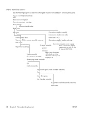
Formatter Note: some formatters Duplex assembly Laser/scanner assembly will include an Asian character control panel dispaly PCA. Figure 5-2 Parts-removal tree ADF Bezel and control panel Convenience stapler ... power supply Note: Convenience stapler components are only for the HP LaserJet M2727nfs. Parts removal order Use the following diagram to determine which parts must be removed before removing other parts. Memory-tag reader assembly Fan Interlock assembly Duplex-drive gears (Note: formatter removed) Fuser Main drive gears Tray 2 pickup assembly ECU (Note...
Formatter Note: some formatters Duplex assembly Laser/scanner assembly will include an Asian character control panel dispaly PCA. Figure 5-2 Parts-removal tree ADF Bezel and control panel Convenience stapler ... power supply Note: Convenience stapler components are only for the HP LaserJet M2727nfs. Parts removal order Use the following diagram to determine which parts must be removed before removing other parts. Memory-tag reader assembly Fan Interlock assembly Duplex-drive gears (Note: formatter removed) Fuser Main drive gears Tray 2 pickup assembly ECU (Note...

Service Manual
Page 135
...-harness connectors (callout 2; CAUTION: Do not bend or fold the flat flexible cables (FFCs) during removal or installation. Failure to remove the ferrite from the formatter. See Left cover on page 102. 2. Disconnect two FFC connectors (callout 1; J2 and J36) from the chassis (callout 5), and then feed the cables out through...
...-harness connectors (callout 2; CAUTION: Do not bend or fold the flat flexible cables (FFCs) during removal or installation. Failure to remove the ferrite from the formatter. See Left cover on page 102. 2. Disconnect two FFC connectors (callout 1; J2 and J36) from the chassis (callout 5), and then feed the cables out through...

Service Manual
Page 150
See Left cover on page 102. 2. Failure to electrostatic discharge (ESD). J4, J27, J28, J31, J26). Formatter CAUTION: PCAs are out of 5) 1 2 1 132 Chapter 5 Removal and replacement ENWW You must make sure that all FFCs are fully seated in a PCA. 1. Disconnect five ... in ESD pouches when they are sensitive to fully seat an FFC into a connector can cause a short circuit in their connectors. Figure 5-53 Remove the formatter (1 of the product.
See Left cover on page 102. 2. Failure to electrostatic discharge (ESD). J4, J27, J28, J31, J26). Formatter CAUTION: PCAs are out of 5) 1 2 1 132 Chapter 5 Removal and replacement ENWW You must make sure that all FFCs are fully seated in a PCA. 1. Disconnect five ... in ESD pouches when they are sensitive to fully seat an FFC into a connector can cause a short circuit in their connectors. Figure 5-53 Remove the formatter (1 of the product.

Service Manual
Page 151
Figure 5-55 Install formatter protective sheet ENWW Internal assemblies 133 3. Failure to install the protective sheet might cause a short circuit and damage the formatter. Remove six screws (callout 3), and then separate the formatter from the product. Figure 5-54 Remove the formatter (2 of 5) 3 CAUTION: Make sure that you install the protective sheet behind the formatter when you reinstall it.
Figure 5-55 Install formatter protective sheet ENWW Internal assemblies 133 3. Failure to install the protective sheet might cause a short circuit and damage the formatter. Remove six screws (callout 3), and then separate the formatter from the product. Figure 5-54 Remove the formatter (2 of 5) 3 CAUTION: Make sure that you install the protective sheet behind the formatter when you reinstall it.


