Service Manual
Page 7
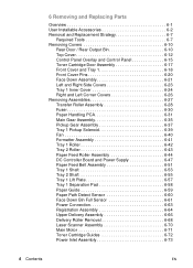
...47 Paper Feed Belt Assembly 6-51 Tray 1 Shaft 6-53 Tray 2 Shaft 6-55 Tray 1 Lift Plate 6-57 Tray 1 Separation Pad 6-58 Paper Guide 6-59 Paper Path Detect Sensor 6-60 Face Down Bin Full Sensor 6-61 Power Connection 6-63 Registration Assembly 6-64 Upper Delivery Assembly 6-66 Delivery Roller Removal... 6-68 Laser Scanner Assembly 6-70 Main Motor 6-71 Toner Cartridge Guides 6-72 Power Inlet...
...47 Paper Feed Belt Assembly 6-51 Tray 1 Shaft 6-53 Tray 2 Shaft 6-55 Tray 1 Lift Plate 6-57 Tray 1 Separation Pad 6-58 Paper Guide 6-59 Paper Path Detect Sensor 6-60 Face Down Bin Full Sensor 6-61 Power Connection 6-63 Registration Assembly 6-64 Upper Delivery Assembly 6-66 Delivery Roller Removal... 6-68 Laser Scanner Assembly 6-70 Main Motor 6-71 Toner Cartridge Guides 6-72 Power Inlet...
Service Manual
Page 166
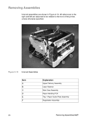
Removing Assemblies Internal assemblies are assumed to be relative to the front of the printer, unless otherwise specified. All references to the right and left are shown in Figure 6-19. Figure 6-19 Internal Assemblies Item A B C D E F Explanation Upper Delivery Assembly Laser Scanner Main Gear Assembly Paper Handling PCA Tray 1 Paper Guide Plate Assembly Registration Assembly EN Removing Assemblies 6-27
Removing Assemblies Internal assemblies are assumed to be relative to the front of the printer, unless otherwise specified. All references to the right and left are shown in Figure 6-19. Figure 6-19 Internal Assemblies Item A B C D E F Explanation Upper Delivery Assembly Laser Scanner Main Gear Assembly Paper Handling PCA Tray 1 Paper Guide Plate Assembly Registration Assembly EN Removing Assemblies 6-27
Service Manual
Page 167
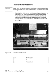
... fingers. Figure 6-20 Transfer Guide Removal Item A B Explanation Screws Transfer Guide 6-28 Removing and Replacing Parts EN Roll it up in a clean sheet of the Registration Assembly, exposing the Transfer Guide (the metal plate that rests against the Transfer Roller). CAUTION Transfer Roller...
... fingers. Figure 6-20 Transfer Guide Removal Item A B Explanation Screws Transfer Guide 6-28 Removing and Replacing Parts EN Roll it up in a clean sheet of the Registration Assembly, exposing the Transfer Guide (the metal plate that rests against the Transfer Roller). CAUTION Transfer Roller...
Service Manual
Page 180
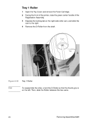
Then, slide the Roller between the two cams. EN Removing Assemblies 6-41 Cam Locking Tab Figure 6-32 Tray 1 Roller Hint To reassemble the roller, orient the D-Roller so that the thumb grip is on the right side roller cam, and slide the cam to the right. 4 Remove the D-Roller from the shaft. Tray 1 Roller 1 Open the Top Cover and remove the Toner Cartridge. 2 Facing the front of the printer, raise the green center handle of the Registration Assembly. 3 Depress the locking tab on the left.
Then, slide the Roller between the two cams. EN Removing Assemblies 6-41 Cam Locking Tab Figure 6-32 Tray 1 Roller Hint To reassemble the roller, orient the D-Roller so that the thumb grip is on the right side roller cam, and slide the cam to the right. 4 Remove the D-Roller from the shaft. Tray 1 Roller 1 Open the Top Cover and remove the Toner Cartridge. 2 Facing the front of the printer, raise the green center handle of the Registration Assembly. 3 Depress the locking tab on the left.
Service Manual
Page 182
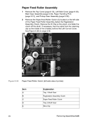
... (left side of the Paper Feed Roller Assembly, below the Registration Assembly Clutch. Paper Feed Roller Assembly 1 Remove the Top Cover (page 6-12), Left Side Cover (page 6-23), Main Gear Assembly (page 6-34), Paper Handling PCA (page 6-31), and Pickup Gear Assembly (page 6-36). 2 Remove the Paper ... located on the left side view of printer) Item A B C D E Explanation Tray 1 Shaft Gear Registration Assembly Clutch Paper Feed Roller Clutch Tray 2 Shaft Gear Wire Clip EN Removing Assemblies 6-43 Remove the E-Clip on the inside of the chassis, behind the Left Corner Cover. See Figure 6-28...
... (left side of the Paper Feed Roller Assembly, below the Registration Assembly Clutch. Paper Feed Roller Assembly 1 Remove the Top Cover (page 6-12), Left Side Cover (page 6-23), Main Gear Assembly (page 6-34), Paper Handling PCA (page 6-31), and Pickup Gear Assembly (page 6-36). 2 Remove the Paper ... located on the left side view of printer) Item A B C D E Explanation Tray 1 Shaft Gear Registration Assembly Clutch Paper Feed Roller Clutch Tray 2 Shaft Gear Wire Clip EN Removing Assemblies 6-43 Remove the E-Clip on the inside of the chassis, behind the Left Corner Cover. See Figure 6-28...
Service Manual
Page 183
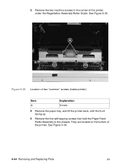
See Figure 6-36. 6-44 Removing and Replacing Parts EN See Figure 6-35. They are located on the bottom of two "common" screws (inside printer) Item A Explanation Screws 4 Remove the paper tray, and tilt the printer back, with the front facing up. 5 Remove the five self-tapping screws that hold the Paper Feed Roller Assembly to the chassis. Figure 6-35 Location of the printer. 3 Remove the two machine screws in the center of the printer, under the Registration Assembly Roller Guide.
See Figure 6-36. 6-44 Removing and Replacing Parts EN See Figure 6-35. They are located on the bottom of two "common" screws (inside printer) Item A Explanation Screws 4 Remove the paper tray, and tilt the printer back, with the front facing up. 5 Remove the five self-tapping screws that hold the Paper Feed Roller Assembly to the chassis. Figure 6-35 Location of the printer. 3 Remove the two machine screws in the center of the printer, under the Registration Assembly Roller Guide.
Service Manual
Page 189
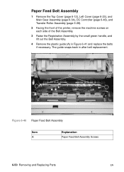
... belts if necessary. Figure 6-40 Paper Feed Belt Assembly Item A Explanation Paper Feed Belt Assembly Screws 6-50 Removing and Replacing Parts EN Paper Feed Belt Assembly 1 Remove the Top Cover (page 6-12), Left Cover (page 6-23), and Main Gear Assembly (page 6-34), DC Controller (page 6-46), ...and Transfer Roller Assembly (page 6-28). 2 Facing the front of the printer, remove the machine screws on each side of the Belt Assembly. 3 Raise the Registration Assembly by the small green handle, and lift out ...
... belts if necessary. Figure 6-40 Paper Feed Belt Assembly Item A Explanation Paper Feed Belt Assembly Screws 6-50 Removing and Replacing Parts EN Paper Feed Belt Assembly 1 Remove the Top Cover (page 6-12), Left Cover (page 6-23), and Main Gear Assembly (page 6-34), DC Controller (page 6-46), ...and Transfer Roller Assembly (page 6-28). 2 Facing the front of the printer, remove the machine screws on each side of the Belt Assembly. 3 Raise the Registration Assembly by the small green handle, and lift out ...
Service Manual
Page 191
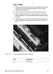
.... Tray 1 Shaft 1 Remove the Top Cover (page 6-12), Left and Right Side Covers (page 6-23), Pickup Gear Assembly (page 6-36), and Paper Handling PCA (page 6-31). 2 Raise the green center handle of the Registration Assembly. 3 Remove the plastic collar on the right, outside the chassis, by pulling outward on the collar's release tab...
.... Tray 1 Shaft 1 Remove the Top Cover (page 6-12), Left and Right Side Covers (page 6-23), Pickup Gear Assembly (page 6-36), and Paper Handling PCA (page 6-31). 2 Raise the green center handle of the Registration Assembly. 3 Remove the plastic collar on the right, outside the chassis, by pulling outward on the collar's release tab...
Service Manual
Page 197
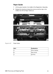
Figure 6-47 Paper Guide Item A B C Explanation Green Handles Paper Guide End Pins 6-58 Removing and Replacing Parts EN Paper Guide 1 Lift the green handle in the middle of the Registration Assembly. 2 Release the Guide by freeing the end pins and the clips in the middle, then lift the Paper Guide out.
Figure 6-47 Paper Guide Item A B C Explanation Green Handles Paper Guide End Pins 6-58 Removing and Replacing Parts EN Paper Guide 1 Lift the green handle in the middle of the Registration Assembly. 2 Release the Guide by freeing the end pins and the clips in the middle, then lift the Paper Guide out.
Service Manual
Page 202
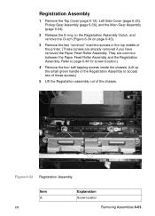
...two "common" machine screws in the top middle of the chassis. Figure 6-52 Registration Assembly Item A EN Explanation Screw location Removing Assemblies 6-63 They are already removed if you have removed the Paper Feed Roller Assembly. Refer to page 6-44 for screw location.) 4 Remove the four self-tapping... screws inside the chassis. (Lift up the small green handle of the Registration Assembly to access two of these screws.) 5 Lift the Registration assembly out of the printer. (...
...two "common" machine screws in the top middle of the chassis. Figure 6-52 Registration Assembly Item A EN Explanation Screw location Removing Assemblies 6-63 They are already removed if you have removed the Paper Feed Roller Assembly. Refer to page 6-44 for screw location.) 4 Remove the four self-tapping... screws inside the chassis. (Lift up the small green handle of the Registration Assembly to access two of these screws.) 5 Lift the Registration assembly out of the printer. (...
Service Manual
Page 203
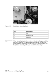
Figure 6-53 Registration Assembly Clutch Item A B C Explanation Flat Alignment Tab Stabilizer Hint When reinstalling the clutch, orient the shaft with the flat spot up. Make sure that the cable is situated away from the Registration Assembly before you reinstall the Assembly. 6-64 Removing and Replacing Parts EN When the clutch slides on, the slotted metal alignment tab will seat onto a plastic stabilizer.
Figure 6-53 Registration Assembly Clutch Item A B C Explanation Flat Alignment Tab Stabilizer Hint When reinstalling the clutch, orient the shaft with the flat spot up. Make sure that the cable is situated away from the Registration Assembly before you reinstall the Assembly. 6-64 Removing and Replacing Parts EN When the clutch slides on, the slotted metal alignment tab will seat onto a plastic stabilizer.
Service Manual
Page 247
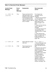
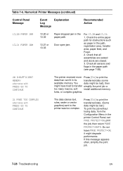
paper path for obstructions such as paper in the path. 2. Open and close the top cover to the Registration Assembly, or the Transfer Roller out of sensors, see page 7-88. 13.1 PAPER JAM 13.2 PAPER JAM 13.01 13.02 Paper delay jam at paper ...
paper path for obstructions such as paper in the path. 2. Open and close the top cover to the Registration Assembly, or the Transfer Roller out of sensors, see page 7-88. 13.1 PAPER JAM 13.2 PAPER JAM 13.01 13.02 Paper delay jam at paper ...
Service Manual
Page 249
... and 13.21: 1. it might be lost .) To print the job without losing data, from the Configuration Menu in the path, registration area, transfer area, paper feed, and Fuser. 2. Check all assemblies are seated and doors are closed. 3. If this message appears often, simplify the print job. 7-28 Troubleshooting EN Table 7-6. Numerical...
... and 13.21: 1. it might be lost .) To print the job without losing data, from the Configuration Menu in the path, registration area, transfer area, paper feed, and Fuser. 2. Check all assemblies are seated and doors are closed. 3. If this message appears often, simplify the print job. 7-28 Troubleshooting EN Table 7-6. Numerical...
Service Manual
Page 289
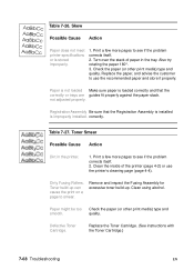
...EN Paper is not loaded Make sure paper is loaded correctly and that the Registration Assembly is installed is stored improperly. 1. Clean the inside of paper in the printer. 1. Remove and inspect the Fusing Assembly for excessive toner build-up can cause the print on a page to ...Smear Possible Cause Action Dirt in the tray. Paper might be too Check the paper (or other print media) type and quality. Registration Assembly Be sure that the correctly or trays are guides fit properly against the paper stack. correctly. Check the paper (or other print media...
...EN Paper is not loaded Make sure paper is loaded correctly and that the Registration Assembly is installed is stored improperly. 1. Clean the inside of paper in the printer. 1. Remove and inspect the Fusing Assembly for excessive toner build-up can cause the print on a page to ...Smear Possible Cause Action Dirt in the tray. Paper might be too Check the paper (or other print media) type and quality. Registration Assembly Be sure that the correctly or trays are guides fit properly against the paper stack. correctly. Check the paper (or other print media...
Service Manual
Page 339
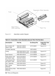
...-3519-000CN Upper Delivery Roller RG5-3542-000CN Assembly Exploded View in Figure Figure 8-16 Figure 8-18 Figure 8-7 Figure 8-16 Figure 8-16 Figure 8-2 Figure 8-5 Figure 8-8 8-8 Parts and Diagrams EN Fuser Registration Roller Assembly Paper Pickup Roller Assembly Toner Cartridge Paper Tray Figure 8-1 Assembly Location Diagram Table 8-4. Exchange No. Assemblies Listed Alphabetically and Their Part Numbers Description...
...-3519-000CN Upper Delivery Roller RG5-3542-000CN Assembly Exploded View in Figure Figure 8-16 Figure 8-18 Figure 8-7 Figure 8-16 Figure 8-16 Figure 8-2 Figure 8-5 Figure 8-8 8-8 Parts and Diagrams EN Fuser Registration Roller Assembly Paper Pickup Roller Assembly Toner Cartridge Paper Tray Figure 8-1 Assembly Location Diagram Table 8-4. Exchange No. Assemblies Listed Alphabetically and Their Part Numbers Description...

Service Manual
Page 340
Table 8-4. Exploded View in Figure Figure 8-11 Figure 8-10 Figure 8-12 EN Illustrations and Parts Lists 8-9 Assemblies Listed Alphabetically and Their Part Numbers (continued) Description Part No. Paper Feed Roller Assembly Paper Feed Belt Registration Roller Assembly RG5-3522-000CN RG5-3526-000CN RG5-3524-000CN Exchange No.
Table 8-4. Exploded View in Figure Figure 8-11 Figure 8-10 Figure 8-12 EN Illustrations and Parts Lists 8-9 Assemblies Listed Alphabetically and Their Part Numbers (continued) Description Part No. Paper Feed Roller Assembly Paper Feed Belt Registration Roller Assembly RG5-3522-000CN RG5-3526-000CN RG5-3524-000CN Exchange No.
Service Manual
Page 376
Description Rear Door Sensor Assembly Registration Roller Assembly Return Cover, 500-sheet Feeder Right Auxiliary Cover, 500-sheet Feeder Right Bushing Right Bushing Lower Delivery Roller Right Corner Cover Right Cover, 500-sheet ...Feeder Right Latch Block Right Latch Plate Right Mount Right Pickup Roller Bushing Right Pickup Roller Collar Right Roller Cam Right Side Cover Assembly Roller Holder Roller Mount 1 Roller Spring Screw, Long DC Controller Screws (M3x25) Screw, M3x4 TP Screw, M3x6 TP Screw, M3x8 TP Screw Screw, M4x10 Pan...
Description Rear Door Sensor Assembly Registration Roller Assembly Return Cover, 500-sheet Feeder Right Auxiliary Cover, 500-sheet Feeder Right Bushing Right Bushing Lower Delivery Roller Right Corner Cover Right Cover, 500-sheet ...Feeder Right Latch Block Right Latch Plate Right Mount Right Pickup Roller Bushing Right Pickup Roller Collar Right Roller Cam Right Side Cover Assembly Roller Holder Roller Mount 1 Roller Spring Screw, Long DC Controller Screws (M3x25) Screw, M3x4 TP Screw, M3x6 TP Screw, M3x8 TP Screw Screw, M4x10 Pan...

Service Manual
Page 381
... 8-8 on page 8-17 Tray 1 Paper Guide Plate Assembly Table 8-7 on page 8-14 Paper Pickup Roller Assembly (Tray 2) Table 8-12 on page 8-23 Paper Feed Roller Assembly Table 8-14 on page 8-27 Sensor Cable Table 8-14 on page 8-27 Registration Roller Assembly Table 8-15 on page 8-29 Transfer Guide Assembly Table 8-9 on page 8-19 Paper Feed Belt...
... 8-8 on page 8-17 Tray 1 Paper Guide Plate Assembly Table 8-7 on page 8-14 Paper Pickup Roller Assembly (Tray 2) Table 8-12 on page 8-23 Paper Feed Roller Assembly Table 8-14 on page 8-27 Sensor Cable Table 8-14 on page 8-27 Registration Roller Assembly Table 8-15 on page 8-29 Transfer Guide Assembly Table 8-9 on page 8-19 Paper Feed Belt...
Service Manual
Page 386
...Memory (RAM) 5-15 Rear Door/Rear Output Bin, removing and replacing 6-10 recycling toner cartridges 2-8 refeed system 5-38 Registration Assembly, removing and replacing 6- 64 regulatory information 1-22- 1-24 removal/replacement strategy 6-7 removing and replacing 6-10 reset maintenance ... toner cleaning spilled 4-4 consumption 1-26 toner cartridge 2-8, 5-18, 5-20 detection 5-7 recycling 2-8 refilled 2-8 Toner Cartridge Door Assembly, removing and replacing 6-17 Toner Cartridge Guides, removing and replacing 672 tools 6-7 Top Cover, removing and replacing 6-12 training media 2-4 Transfer Roller...
...Memory (RAM) 5-15 Rear Door/Rear Output Bin, removing and replacing 6-10 recycling toner cartridges 2-8 refeed system 5-38 Registration Assembly, removing and replacing 6- 64 regulatory information 1-22- 1-24 removal/replacement strategy 6-7 removing and replacing 6-10 reset maintenance ... toner cleaning spilled 4-4 consumption 1-26 toner cartridge 2-8, 5-18, 5-20 detection 5-7 recycling 2-8 refilled 2-8 Toner Cartridge Door Assembly, removing and replacing 6-17 Toner Cartridge Guides, removing and replacing 672 tools 6-7 Top Cover, removing and replacing 6-12 training media 2-4 Transfer Roller...


