HP LaserJet 4000 Printer Series - HP LaserJet 4000, 4000 T, 4000 N, and 4000 TN Printers - User's Guide
Page 70
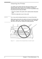
...on or around the printer. While cleaning the printer, be careful not to touch the transfer roller (the black, rubber roller, located underneath the toner cartridge). Do not use ammonia-based cleaners on the roller can cause print quality problems. Figure 17 Location of the printer with a slightly water...dry, lint-free cloth. As much as possible, keep the printer free from dust and debris. • Clean the outside of the Transfer Roller-Do Not Touch! EN Chapter 3: Printer Maintenance 59 Caution Cleaning the Printer To maintain print quality, follow the cleaning procedure (on the ...
...on or around the printer. While cleaning the printer, be careful not to touch the transfer roller (the black, rubber roller, located underneath the toner cartridge). Do not use ammonia-based cleaners on the roller can cause print quality problems. Figure 17 Location of the printer with a slightly water...dry, lint-free cloth. As much as possible, keep the printer free from dust and debris. • Clean the outside of the Transfer Roller-Do Not Touch! EN Chapter 3: Printer Maintenance 59 Caution Cleaning the Printer To maintain print quality, follow the cleaning procedure (on the ...
Service Manual
Page 6
... a 04 Self test 3-12 15 Engine Test 3-13 Font Test Pages 3-14 LaserJet IIISi 3-14 LaserJet 4Si 3-14 Demo Pages (LaserJet 4Si Only) 3-16 4. Maintenance INTRODUCTION 4-1 User Maintenance Concept 4-1 PRINTER CONSUMABLES 4-1 TONER CARTRIDGE LIFE EXPECTANCY . 4-2 VERIFYING PRINTER MAINTENANCE 4-3 USER MAINTENANCE 4-4 Fusing Assembly 4-5 Transfer Roller 4-7 Transfer Roller Replacement 4-8 Contents-2 Site Planning and Requirements INTRODUCTION 2-1 SITE REQUIREMENTS 2-1 Print Media...
... a 04 Self test 3-12 15 Engine Test 3-13 Font Test Pages 3-14 LaserJet IIISi 3-14 LaserJet 4Si 3-14 Demo Pages (LaserJet 4Si Only) 3-16 4. Maintenance INTRODUCTION 4-1 User Maintenance Concept 4-1 PRINTER CONSUMABLES 4-1 TONER CARTRIDGE LIFE EXPECTANCY . 4-2 VERIFYING PRINTER MAINTENANCE 4-3 USER MAINTENANCE 4-4 Fusing Assembly 4-5 Transfer Roller 4-7 Transfer Roller Replacement 4-8 Contents-2 Site Planning and Requirements INTRODUCTION 2-1 SITE REQUIREMENTS 2-1 Print Media...
Service Manual
Page 12
... Locations (Top Cover open) 4-9. Sample Laser Safety Label 2-1. Sample Power Plot 3-1. LaserJet 4Si Menu Map 3-4. Removing the Transfer Roller 4-6. Front Upper Cover Contents-S 1-3 1-4 1-5 1-9 2-2 2-4 3-3 3-3 3-4 3-8 3-10 3-13 3-15 3-16 4-2 4-3 4-5 4-6 4-7 4-9 4-10 4-12 4-13 4-14 4-15 5-3 5-4 5-5 5-8 6-2 6-3 6-4 LaserJet IIISi/4Si Space Requirements 2-2. The LaserJet IIISi Control Panel 3-2. The LaserJet 4Si Control Panel 3-3. TAserJet IIISi 05 Self test Printout 3-5. Engine Test Button...
... Locations (Top Cover open) 4-9. Sample Laser Safety Label 2-1. Sample Power Plot 3-1. LaserJet 4Si Menu Map 3-4. Removing the Transfer Roller 4-6. Front Upper Cover Contents-S 1-3 1-4 1-5 1-9 2-2 2-4 3-3 3-3 3-4 3-8 3-10 3-13 3-15 3-16 4-2 4-3 4-5 4-6 4-7 4-9 4-10 4-12 4-13 4-14 4-15 5-3 5-4 5-5 5-8 6-2 6-3 6-4 LaserJet IIISi/4Si Space Requirements 2-2. The LaserJet IIISi Control Panel 3-2. The LaserJet 4Si Control Panel 3-3. TAserJet IIISi 05 Self test Printout 3-5. Engine Test Button...
Service Manual
Page 64
Maintenance INTRODUCTION 4-1 User Maintenance Concept 4-1 PRINTER CONSUMABLES 4-1 TONER CARTRIDGE LIFE EXPECTANCY . 4-2 VERIFYING PRINTER MAINTENANCE 4-3 USER MAINTENANCE 4-4 Fusing Assembly 4-5 Transfer Roller 4-7 Transfer Roller Replacement 4-8 Pickup and Separation Rollers 4-9 Duplex D-Roller 4-10 CLEANING THE PRINTER 4-11 Registration Area 4-13 Antistatic Teeth 4-14 Transfer Guide 4-15 Clearing the User Maintenance Message 4-16 Contents 4.
Maintenance INTRODUCTION 4-1 User Maintenance Concept 4-1 PRINTER CONSUMABLES 4-1 TONER CARTRIDGE LIFE EXPECTANCY . 4-2 VERIFYING PRINTER MAINTENANCE 4-3 USER MAINTENANCE 4-4 Fusing Assembly 4-5 Transfer Roller 4-7 Transfer Roller Replacement 4-8 Pickup and Separation Rollers 4-9 Duplex D-Roller 4-10 CLEANING THE PRINTER 4-11 Registration Area 4-13 Antistatic Teeth 4-14 Transfer Guide 4-15 Clearing the User Maintenance Message 4-16 Contents 4.
Service Manual
Page 65
Removing the Duplex D-Roller 4-8. Removing the Pickup and Separation Rollers 4-7. Removing the Transfer Roller 4-6. Cleaning the Transfer Guide 4-2 4-3 4-5 4-6 4-7 4-9 4-10 4-12 4-13 4-14 4-15 Figures 4-1. Cleaning the Antistatic Teeth 4-11. Removing the Fusing Assembly Screws 4-4. Printer Component Locations (Top Cover open) 4-9. Sample 5% Page Coverage 4-2. Location of Printer Maintenance Parts 4-3. Removing the Fusing Assembly 4-5. Cleaning the Registration Area 4-10.
Removing the Duplex D-Roller 4-8. Removing the Pickup and Separation Rollers 4-7. Removing the Transfer Roller 4-6. Cleaning the Transfer Guide 4-2 4-3 4-5 4-6 4-7 4-9 4-10 4-12 4-13 4-14 4-15 Figures 4-1. Cleaning the Antistatic Teeth 4-11. Removing the Fusing Assembly Screws 4-4. Printer Component Locations (Top Cover open) 4-9. Sample 5% Page Coverage 4-2. Location of Printer Maintenance Parts 4-3. Removing the Fusing Assembly 4-5. Cleaning the Registration Area 4-10.
Service Manual
Page 68
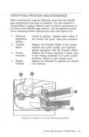
...printer maintenance parts (see Figure 4-2). 1. Duplex D-Roller Check for glazing. Pickup & Separation Rollers 2. Location of Printer Maintenance Parts Printer Maintenance: VERIFYING 4-3 VERIFYING PRINTER MAINTENANCE Before servicing the LaserJet IIISi/4Si, check that the 200,000 page maintenance...'s responsibility to poor fusing occur. Transfer Roller 3. Replace these rollers if the printer has paper input jam problems. Replace the Trarsfer Roller if the printer exhibits poor print quality and repetitive defects associated with the Transfer Roller. Replace as indicated by glazing and...
...printer maintenance parts (see Figure 4-2). 1. Duplex D-Roller Check for glazing. Pickup & Separation Rollers 2. Location of Printer Maintenance Parts Printer Maintenance: VERIFYING 4-3 VERIFYING PRINTER MAINTENANCE Before servicing the LaserJet IIISi/4Si, check that the 200,000 page maintenance...'s responsibility to poor fusing occur. Transfer Roller 3. Replace these rollers if the printer has paper input jam problems. Replace the Trarsfer Roller if the printer exhibits poor print quality and repetitive defects associated with the Transfer Roller. Replace as indicated by glazing and...
Service Manual
Page 69
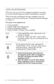
...gloves provided when replacing the Transfer Roller. Severe personal injury may result from the hot Fusing Assembly. 44 Printer Maintenance: USER MAINTENANCE Fusing Assembly. 2. Note 1. The terms, "right" and "left", used in these procedures assume that you are : 1. Do not touch the roller without using clean gloves.... Duplex Unit is the reverse of the printer. Unless specifically noted, replacement is installed). Natural skin oils will contaminate the Transfer Roller. 1. USER MAINTENANCE When the IYE-;ER VIA I tITEHANCE message is displayed, the printer has printed 200,000 pages and ...
...gloves provided when replacing the Transfer Roller. Severe personal injury may result from the hot Fusing Assembly. 44 Printer Maintenance: USER MAINTENANCE Fusing Assembly. 2. Note 1. The terms, "right" and "left", used in these procedures assume that you are : 1. Do not touch the roller without using clean gloves.... Duplex Unit is the reverse of the printer. Unless specifically noted, replacement is installed). Natural skin oils will contaminate the Transfer Roller. 1. USER MAINTENANCE When the IYE-;ER VIA I tITEHANCE message is displayed, the printer has printed 200,000 pages and ...
Service Manual
Page 72
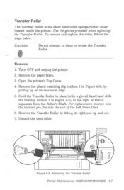
... provided when replacing the Transfer Roller. To remove and replace the roller, follow the steps below. Caution Do not attempt to the right so that it separates from the Roller's Shaft. Transfer Roller The Transfer Roller is the black conductive sponge-rubber roller located inside the printer. Turn OFF and unplug the printer. 2. Removing the Transfer Roller Printer Maintenance: USER MAINTENANCE...
... provided when replacing the Transfer Roller. To remove and replace the roller, follow the steps below. Caution Do not attempt to the right so that it separates from the Roller's Shaft. Transfer Roller The Transfer Roller is the black conductive sponge-rubber roller located inside the printer. Turn OFF and unplug the printer. 2. Removing the Transfer Roller Printer Maintenance: USER MAINTENANCE...
Service Manual
Page 73
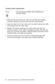
... will travel the full length of the Transfer Roller and right end bushing. 4. Close the printer and run a self test. Transfer Roller Replacement Note IF Use the gloves provided when handling the Transfer Roller. 1. Slide the left end of the roller with the right bushing and slide the bushing onto the roller shaft. 3. Check that paper will snap...
... will travel the full length of the Transfer Roller and right end bushing. 4. Close the printer and run a self test. Transfer Roller Replacement Note IF Use the gloves provided when handling the Transfer Roller. 1. Slide the left end of the roller with the right bushing and slide the bushing onto the roller shaft. 3. Check that paper will snap...

Service Manual
Page 76
...the printer OFF and unplug the power cord before servicing the printer. Printer Maintenance: CLEANING THE PRINTER 4-11 Do not touch or clean the Transfer Roller without gloves when servicing the printer. Failure to follow this section when cleaning the printer. Note If toner gets on the... Transfer Roller may result in this warning may reduce print quality. 2. Caution fi 1. Never use ammonia-based cleaning solutions to clean the printer. Use a water ...
...the printer OFF and unplug the power cord before servicing the printer. Printer Maintenance: CLEANING THE PRINTER 4-11 Do not touch or clean the Transfer Roller without gloves when servicing the printer. Failure to follow this section when cleaning the printer. Note If toner gets on the... Transfer Roller may result in this warning may reduce print quality. 2. Caution fi 1. Never use ammonia-based cleaning solutions to clean the printer. Use a water ...

Service Manual
Page 77
Anti-Static Teeth 3. Upper Paper Path Access 4. Transfer Guide 7. Fusing Assembly 4-12 Printer Maintenance: CLEANING THE PRINTER Cleaning Brush 6. Printer Component Locations (Top Cover open) 1. Registration Guide 5. Transfer Roller 2. i______111111111111111 0 0 0 C t l Figure 4-8.
Anti-Static Teeth 3. Upper Paper Path Access 4. Transfer Guide 7. Fusing Assembly 4-12 Printer Maintenance: CLEANING THE PRINTER Cleaning Brush 6. Printer Component Locations (Top Cover open) 1. Registration Guide 5. Transfer Roller 2. i______111111111111111 0 0 0 C t l Figure 4-8.

Service Manual
Page 78
Caution Do not touch or clean the Transfer Roller when cleaning the printer. Reduced print quality may result. 4. Cleaning the Registration Area Printer Maintenance. Turn the printer OFF and unplug the power cord. 2. With a ...
Caution Do not touch or clean the Transfer Roller when cleaning the printer. Reduced print quality may result. 4. Cleaning the Registration Area Printer Maintenance. Turn the printer OFF and unplug the power cord. 2. With a ...

Service Manual
Page 79
... Figure 4-10). 2. Use the brush provided to avoid injury to yourself, or damage to touch the Transfer Roller when cleaning the Antistatic Teeth. 2. Caution 1. Be careful not to the teeth. 1. Locate the Antistatic Teeth in its holder. 1 I I L Figure 4-10. Antistatic Teeth Use the ...
... Figure 4-10). 2. Use the brush provided to avoid injury to yourself, or damage to touch the Transfer Roller when cleaning the Antistatic Teeth. 2. Caution 1. Be careful not to the teeth. 1. Locate the Antistatic Teeth in its holder. 1 I I L Figure 4-10. Antistatic Teeth Use the ...

Service Manual
Page 80
Transfer Guide Wipe any dust or dirt off the Transfer Guide (see Figure 4-11) with a damp cloth (use water only). Warning The Fusing Assembly remains hot for thirty minutes after turning the printer OFF. Be careful not to touch the Transfer Roller. Cleaning the Transfer Guide Printer Maintenance: CLEANING THE PRINTER 4-15 Figure 4-11.
Transfer Guide Wipe any dust or dirt off the Transfer Guide (see Figure 4-11) with a damp cloth (use water only). Warning The Fusing Assembly remains hot for thirty minutes after turning the printer OFF. Be careful not to touch the Transfer Roller. Cleaning the Transfer Guide Printer Maintenance: CLEANING THE PRINTER 4-15 Figure 4-11.

Service Manual
Page 85
... the paper and held in Figure 5-1. 5-2 Functional Overview: IMAGE FORMATION SYSTEM A cross-section of the drum exposed by a slight electrostatic charge on the Transfer Roller. 6. Fusing: Heat and pressure fuse the image onto the paper. Developing: Toner is an operator's task, it eliminates the need for a service call when these ...
... the paper and held in Figure 5-1. 5-2 Functional Overview: IMAGE FORMATION SYSTEM A cross-section of the drum exposed by a slight electrostatic charge on the Transfer Roller. 6. Fusing: Heat and pressure fuse the image onto the paper. Developing: Toner is an operator's task, it eliminates the need for a service call when these ...

Service Manual
Page 91
Power switch ON 190*C PRNT V V WAIT TBY INTR PRNT PRINT READY indicator Fusing Roller Heater Main Motor Transfer Roller Scanner Motor Primary Charging Roller (DC) Primary Charging Roller (AC) VERTICAL SYNC REQUEST Developing bias (DC) Developing bias (AC) Registration Roller Clutch Solenoid Laser Diode 190°C100°C !III4/41 4-42,5 -1500V 1.1sec. 190°C 4-ic 2.5 sec MI About 0.3 sec. -H- 0.03 sec. - 0.05 sec. - 0.02 sec. • MIN LSTR1 LSTR2 LSTR3l STBY E co 1800C rcan O C) -1500V H (I; 61. 'f Ln a) iZ fi Functional Overview: SEQUENCE OF OPERATION
Power switch ON 190*C PRNT V V WAIT TBY INTR PRNT PRINT READY indicator Fusing Roller Heater Main Motor Transfer Roller Scanner Motor Primary Charging Roller (DC) Primary Charging Roller (AC) VERTICAL SYNC REQUEST Developing bias (DC) Developing bias (AC) Registration Roller Clutch Solenoid Laser Diode 190°C100°C !III4/41 4-42,5 -1500V 1.1sec. 190°C 4-ic 2.5 sec MI About 0.3 sec. -H- 0.03 sec. - 0.05 sec. - 0.02 sec. • MIN LSTR1 LSTR2 LSTR3l STBY E co 1800C rcan O C) -1500V H (I; 61. 'f Ln a) iZ fi Functional Overview: SEQUENCE OF OPERATION

Service Manual
Page 130
Paper Refeed Unit (PRU) 4. Laser/Scanner Assembly 2. Refer to Chapter 4 for removing the following Internal Assemblies: 1. Registration Assembly 3. Main Motor Drive Train Note a ir Internal Assemblies also include the Transfer Roller and Fusing Assembly. INTERNAL ASSEMBLIES This section lists procedures for removal procedures. 6-34 Removal & Replacement: INTERNAL ASSEMBLIES Transfer Guide 5. High Voltage Power Supply 6.
Paper Refeed Unit (PRU) 4. Laser/Scanner Assembly 2. Refer to Chapter 4 for removing the following Internal Assemblies: 1. Registration Assembly 3. Main Motor Drive Train Note a ir Internal Assemblies also include the Transfer Roller and Fusing Assembly. INTERNAL ASSEMBLIES This section lists procedures for removal procedures. 6-34 Removal & Replacement: INTERNAL ASSEMBLIES Transfer Guide 5. High Voltage Power Supply 6.

Service Manual
Page 132
... in its fully actuated position, and carefully mate the Registration Assembly gears to the solenoid. ■ oi 1,0 O(T O Figure 6-29. On the right end of the Transfer Roller, remove the (1) retaining clip (see Figure 6-29, callout 4). Remove the (2) screws securing the Registration Assembly Guide and lift off the guide (see Figure 6-29, callout...
... in its fully actuated position, and carefully mate the Registration Assembly gears to the solenoid. ■ oi 1,0 O(T O Figure 6-29. On the right end of the Transfer Roller, remove the (1) retaining clip (see Figure 6-29, callout 4). Remove the (2) screws securing the Registration Assembly Guide and lift off the guide (see Figure 6-29, callout...

Service Manual
Page 134
..., callout 1). Note Older models of the LaserJet IIISi use a star washer only on the far left inner side of the printer, slide the plastic Side Cover upward to remove. Be certain to the side of the Transfer Roller. 3. Transfer Guide 6-38 Removal & Replacement: INTERNAL ASSEMBLIES... This cover is held firmly in its correct location. DO NOT PULL OUTWARD. Remove the Transfer Roller's plastic retaining clip from the right end of the printer....
..., callout 1). Note Older models of the LaserJet IIISi use a star washer only on the far left inner side of the printer, slide the plastic Side Cover upward to remove. Be certain to the side of the Transfer Roller. 3. Transfer Guide 6-38 Removal & Replacement: INTERNAL ASSEMBLIES... This cover is held firmly in its correct location. DO NOT PULL OUTWARD. Remove the Transfer Roller's plastic retaining clip from the right end of the printer....

Service Manual
Page 135
...Power Supply 1. O 3 Figure 6-32. Open the printer. 2. Remove the Transfer Roller (see Figure 6-32, callout 3). High Voltage Power Supply Removal & Replacement: INTERNAL ASSEMBLIES 6-39 Use gloves when handling the Transfer Roller. 4. Slide the High Voltage Power Supply toward the rear of the unit, ...unplug the (1) multi-pin connector and remove the Power Supply (see Chapter 4). Remove the Transfer Guide (see Chapter 4). 3. Remove the Fusing Assembly...
...Power Supply 1. O 3 Figure 6-32. Open the printer. 2. Remove the Transfer Roller (see Figure 6-32, callout 3). High Voltage Power Supply Removal & Replacement: INTERNAL ASSEMBLIES 6-39 Use gloves when handling the Transfer Roller. 4. Slide the High Voltage Power Supply toward the rear of the unit, ...unplug the (1) multi-pin connector and remove the Power Supply (see Chapter 4). Remove the Transfer Guide (see Chapter 4). 3. Remove the Fusing Assembly...


