Service Manual
Page 8
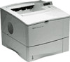
..." Message 7-24 Contents-4 Formatter Pan Assembly (LaserJet IIISi/4Si) Formatter Pan Reassembly Tips Fan FM1 Fan FM2 AC Power Inlet Assembly DC Power Supply DC Controller PCA Power Switch PAPER INPUT UNIT (PIU) AND SUBASSEMBLIES Paper Input Unit (PIU) Paper Input Unit (PIU) PCA INTERNAL ASSEMBLIES Laser/Scanner Assembly Registration Assembly Paper Refeed Unit (PRU) Transfer Guide...
..." Message 7-24 Contents-4 Formatter Pan Assembly (LaserJet IIISi/4Si) Formatter Pan Reassembly Tips Fan FM1 Fan FM2 AC Power Inlet Assembly DC Power Supply DC Controller PCA Power Switch PAPER INPUT UNIT (PIU) AND SUBASSEMBLIES Paper Input Unit (PIU) Paper Input Unit (PIU) PCA INTERNAL ASSEMBLIES Laser/Scanner Assembly Registration Assembly Paper Refeed Unit (PRU) Transfer Guide...

Service Manual
Page 13
.... DC Controller (continued) 6-25. Paper Input Unit (PIU) 6-27. Registration Assembly 6-30. Main Motor Drive Train 6-34. LaserJet 4Si Formatter Pan Assembly 6-18. Left Block 6-37. Control Panel 6-9. Lower Rear Cover 6-12. Formatter PCA (LaserJet 4Si) 6-15. Main Motor Drive Train (continued) 6-36. AC Power Inlet Assembly (continued) 6-22. Transfer Guide 6-32. Right Block 6-39. DC...
.... DC Controller (continued) 6-25. Paper Input Unit (PIU) 6-27. Registration Assembly 6-30. Main Motor Drive Train 6-34. LaserJet 4Si Formatter Pan Assembly 6-18. Left Block 6-37. Control Panel 6-9. Lower Rear Cover 6-12. Formatter PCA (LaserJet 4Si) 6-15. Main Motor Drive Train (continued) 6-36. AC Power Inlet Assembly (continued) 6-22. Transfer Guide 6-32. Right Block 6-39. DC...
Service Manual
Page 15
... Input Unit (Figure 2 of 2) 8-19. Right Main Block Assembly 8-24. Fusing Assembly (2 of 2) 8-12. 8-7. Duplex Unit Assembly 8-16 8-18 8-21 8-22 8-23 8-24 8-25 8-26 8-27 8-28 8-29 8-30 8-30 8-32 8-33 8-34 8-35 8-36 8-37 8-38 Contents-11 Internal Components (Figure 2 of 3) 8-9. Internal Components (Figure 3 of 3) 8-8. Main Motor Drive Train 8-15. Registration Assembly 8-18.
... Input Unit (Figure 2 of 2) 8-19. Right Main Block Assembly 8-24. Fusing Assembly (2 of 2) 8-12. 8-7. Duplex Unit Assembly 8-16 8-18 8-21 8-22 8-23 8-24 8-25 8-26 8-27 8-28 8-29 8-30 8-30 8-32 8-33 8-34 8-35 8-36 8-37 8-38 Contents-11 Internal Components (Figure 2 of 3) 8-9. Internal Components (Figure 3 of 3) 8-8. Main Motor Drive Train 8-15. Registration Assembly 8-18.
Service Manual
Page 17
.... Repetitive Defects 7-31. Large Print Voids 7-38. Duplex Paper Jam Troubleshooting 7-45. Major Assemblies (2 of 2) 8-6. Lifter Assembly 8-13. Any Faint Print Condition 7-25. Bubble Print 7-40. Duplex Assembly Malfunctions 7-46. Paper Input Unit (2 of 3) 8-8. Registration Assembly 7-89 7-90 7-91 7-91 7-92 7-92 7-93 7-98 7-98 7-99 7-100 7-101 7-101 7-102 7-102 7-103 7-104 7-107 7-108...
.... Repetitive Defects 7-31. Large Print Voids 7-38. Duplex Paper Jam Troubleshooting 7-45. Major Assemblies (2 of 2) 8-6. Lifter Assembly 8-13. Any Faint Print Condition 7-25. Bubble Print 7-40. Duplex Assembly Malfunctions 7-46. Paper Input Unit (2 of 3) 8-8. Registration Assembly 7-89 7-90 7-91 7-91 7-92 7-92 7-93 7-98 7-98 7-99 7-100 7-101 7-101 7-102 7-102 7-103 7-104 7-107 7-108...

Service Manual
Page 87
... PICKUP & FEED This causes one sheet of the toner image on the photosensitive drum. The printer's paper path is transferred to the Registration Assembly. At the Registration Assembly, the leading edge of the paper is aligned with the leading edge of paper to be presented to the paper. tr---, 0.---,FR... Roller. The paper is then passed by the Antistatic Teeth where it is electrostatically separated from the drum and transferred to the Fusing Assembly where the toner image is then delivered to the paper. A functional diagram of the Paper Feed Motor, Paper Feed PCA, the Paper...
... PICKUP & FEED This causes one sheet of the toner image on the photosensitive drum. The printer's paper path is transferred to the Registration Assembly. At the Registration Assembly, the leading edge of the paper is aligned with the leading edge of paper to be presented to the paper. tr---, 0.---,FR... Roller. The paper is then passed by the Antistatic Teeth where it is electrostatically separated from the drum and transferred to the Fusing Assembly where the toner image is then delivered to the paper. A functional diagram of the Paper Feed Motor, Paper Feed PCA, the Paper...

Service Manual
Page 94
PAPER INPUT UNIT (PIU) AND SUBASSEMBLIES Paper Input Unit (PIU) Paper Input Unit (PIU) PCA INTERNAL ASSEMBLIES Laser/Scanner Assembly Registration Assembly Paper Refeed Unit (PRU) Transfer Guide High Voltage Power Supply Main Motor Drive Train Left Block Right Block TOP COVER ASSEMBLY AND SUBASSEMBLIES Top Cover Assembly/Hinge Pins Job Offset Assembly Solenoid Clearance Adjustment Delivery Roller Assembly DUPLEX UNIT SUBASSEMBLIES Duplex Unit Duplex PCA 6-32 6-32 6-33 6-34 6-35 6-36 6-37 6-38 6-39 6-40 6-43 6-45 6-47 6-47 6-50 6-52 6-53 6-54 6-54 6-55
PAPER INPUT UNIT (PIU) AND SUBASSEMBLIES Paper Input Unit (PIU) Paper Input Unit (PIU) PCA INTERNAL ASSEMBLIES Laser/Scanner Assembly Registration Assembly Paper Refeed Unit (PRU) Transfer Guide High Voltage Power Supply Main Motor Drive Train Left Block Right Block TOP COVER ASSEMBLY AND SUBASSEMBLIES Top Cover Assembly/Hinge Pins Job Offset Assembly Solenoid Clearance Adjustment Delivery Roller Assembly DUPLEX UNIT SUBASSEMBLIES Duplex Unit Duplex PCA 6-32 6-32 6-33 6-34 6-35 6-36 6-37 6-38 6-39 6-40 6-43 6-45 6-47 6-47 6-50 6-52 6-53 6-54 6-54 6-55

Service Manual
Page 95
Front Upper Cover (continued) 6-5. Front Cover 6-6. Front Cover (continued) 6-7. Front Cover (continued) 6-8. Formatter PCA (LaserJet 4Si) 6-15. LaserJet 4Si Formatter Pan Assembly 6-18. Fan FM1 6-19. Paper Input Unit (PIU) 6-27. Right Rear Cover 6-11. DC Controller 6-24. DC ... FM2 6-20. Registration Assembly 6-30. Transfer Guide 6-32. High Voltage Power Supply 6-2 6-3 6-4 6-5 6-6 6-7 6-8 6-9 6-10 6-11 6-12 6-14 6-16 6-19 6-21 6-21 6-22 6-23 6-24 6-25 6-26 6-27 6-29 6-30 6-31 6-32 6-33 6-35 6-36 6-37 6-38 6-39 DC Power Supply 6-23. LaserJet IIISi PostScript ROM ...
Front Upper Cover (continued) 6-5. Front Cover 6-6. Front Cover (continued) 6-7. Front Cover (continued) 6-8. Formatter PCA (LaserJet 4Si) 6-15. LaserJet 4Si Formatter Pan Assembly 6-18. Fan FM1 6-19. Paper Input Unit (PIU) 6-27. Right Rear Cover 6-11. DC Controller 6-24. DC ... FM2 6-20. Registration Assembly 6-30. Transfer Guide 6-32. High Voltage Power Supply 6-2 6-3 6-4 6-5 6-6 6-7 6-8 6-9 6-10 6-11 6-12 6-14 6-16 6-19 6-21 6-21 6-22 6-23 6-24 6-25 6-26 6-27 6-29 6-30 6-31 6-32 6-33 6-35 6-36 6-37 6-38 6-39 DC Power Supply 6-23. LaserJet IIISi PostScript ROM ...

Service Manual
Page 130
Laser/Scanner Assembly 2. Registration Assembly 3. Paper Refeed Unit (PRU) 4. Main Motor Drive Train Note a ir Internal Assemblies also include the Transfer Roller and Fusing Assembly. Refer to Chapter 4 for removing the following Internal Assemblies: 1. Transfer Guide 5. High Voltage Power Supply 6. INTERNAL ASSEMBLIES This section lists procedures for removal procedures. 6-34 Removal & Replacement: INTERNAL ASSEMBLIES
Laser/Scanner Assembly 2. Registration Assembly 3. Paper Refeed Unit (PRU) 4. Main Motor Drive Train Note a ir Internal Assemblies also include the Transfer Roller and Fusing Assembly. Refer to Chapter 4 for removing the following Internal Assemblies: 1. Transfer Guide 5. High Voltage Power Supply 6. INTERNAL ASSEMBLIES This section lists procedures for removal procedures. 6-34 Removal & Replacement: INTERNAL ASSEMBLIES

Service Manual
Page 132
... carefully mate the Registration Assembly gears to the solenoid. ■ oi 1,0 O(T O Figure 6-29. Registration Assembly 1. Note The Registration Assembly Guide is keyed. Lift the green handle on the Registration Assembly Cover (see Figure 6-29, callout 3) and remove the (2) final screws securing the assembly (see Figure 6-29, callout 1). 3. Registration Assembly 6-36 Removal & Replacement: INTERNAL ASSEMBLIES Remove the (2) screws securing the Registration Assembly Guide and lift...
... carefully mate the Registration Assembly gears to the solenoid. ■ oi 1,0 O(T O Figure 6-29. Registration Assembly 1. Note The Registration Assembly Guide is keyed. Lift the green handle on the Registration Assembly Cover (see Figure 6-29, callout 3) and remove the (2) final screws securing the assembly (see Figure 6-29, callout 1). 3. Registration Assembly 6-36 Removal & Replacement: INTERNAL ASSEMBLIES Remove the (2) screws securing the Registration Assembly Guide and lift...

Service Manual
Page 136
Main Motor Drive Train 1. Remove the Transfer Roller (see Figure 6-32). 7. Remove the High Voltage Power Supply (see Chapter 4). Use gloves when handling the Transfer Roller. 4. Remove the Registration Assembly (see Figure 6-33, callout 1). , • I I 0 T Figure 6-33. Remove the (2) screws securing the Main Motor Cover and remove the cover (see Figure 6-29). 3. Remove the Transfer Guide (see Chapter 4). 5. Main Motor Drive Train 6-40 Removal & Replacement: INTERNAL ASSEMBLIES Remove the Fusing Assembly (see Figure 6-31). 6. Open the printer. 2.
Main Motor Drive Train 1. Remove the Transfer Roller (see Figure 6-32). 7. Remove the High Voltage Power Supply (see Chapter 4). Use gloves when handling the Transfer Roller. 4. Remove the Registration Assembly (see Figure 6-33, callout 1). , • I I 0 T Figure 6-33. Remove the (2) screws securing the Main Motor Cover and remove the cover (see Figure 6-29). 3. Remove the Transfer Guide (see Chapter 4). 5. Main Motor Drive Train 6-40 Removal & Replacement: INTERNAL ASSEMBLIES Remove the Fusing Assembly (see Figure 6-31). 6. Open the printer. 2.

Service Manual
Page 139
...14. Remove the (3) screws securing the Left Block (see Figure 6-2). 3. Removal & Replacement: INTERNAL ASSEMBLIES 6-43 Left Block Read this point, back in their holes before starting the removal. The Registration Assembly (see Figure 6-32). 9. The High Voltage Power Supply (see Figure 6-29). 7. Place the ...screws removed to put all the screws back in their holes after the assembly is removed. From the left side of ...
...14. Remove the (3) screws securing the Left Block (see Figure 6-2). 3. Removal & Replacement: INTERNAL ASSEMBLIES 6-43 Left Block Read this point, back in their holes before starting the removal. The Registration Assembly (see Figure 6-32). 9. The High Voltage Power Supply (see Figure 6-29). 7. Place the ...screws removed to put all the screws back in their holes after the assembly is removed. From the left side of ...

Service Manual
Page 141
...securing the Right Block (see Figure 6-16 or Figure 6-17). 11. The Formatter Pan Assembly (see Figure 6-39, callout 1, These screws are behind the DC Power Supply). 17. The Registration Assembly (see Chapter 4). 7. Unplug connector J007 on the sheet metal, carefully lift the Right ...Block up and towards the center of the Right Block. 18. The Fusing Assembly (see Figure 6-29). 8. The DC Power Supply (see ...
...securing the Right Block (see Figure 6-16 or Figure 6-17). 11. The Formatter Pan Assembly (see Figure 6-39, callout 1, These screws are behind the DC Power Supply). 17. The Registration Assembly (see Chapter 4). 7. Unplug connector J007 on the sheet metal, carefully lift the Right ...Block up and towards the center of the Right Block. 18. The Fusing Assembly (see Figure 6-29). 8. The DC Power Supply (see ...

Service Manual
Page 187
... ""DEFEATING THE TOP COVER INTERLOCK"," later in this location in the main printer body. Additional paper sensors located in the Duplex Assembly are : ■ PS3, the sensor located in the Registration Assembly. ■ PS151, located in the allotted time. For the procedure, refer to remove paper from the entire paper path, including any...
... ""DEFEATING THE TOP COVER INTERLOCK"," later in this location in the main printer body. Additional paper sensors located in the Duplex Assembly are : ■ PS3, the sensor located in the Registration Assembly. ■ PS151, located in the allotted time. For the procedure, refer to remove paper from the entire paper path, including any...

Service Manual
Page 191
...the Pickup/Separation Rollers are correctly installed. Check that the clutch is not installed backwards and that is supported as shown in the LaserJet Family Paper Specification Guide (5002-1801). If this is the case, paper may occur in that the media is very smooth will ...■ Check that area. Troubleshooting: MESSAGE DETAILS 7-33 Check that the lift mechanism is not properly seated accordion jams may jam at the Registration Assembly, remove the toner cartridge, lift the drum shutter and inspect the gears under the shutter. ■ Vary the input and output selection to...
...the Pickup/Separation Rollers are correctly installed. Check that the clutch is not installed backwards and that is supported as shown in the LaserJet Family Paper Specification Guide (5002-1801). If this is the case, paper may occur in that the media is very smooth will ...■ Check that area. Troubleshooting: MESSAGE DETAILS 7-33 Check that the lift mechanism is not properly seated accordion jams may jam at the Registration Assembly, remove the toner cartridge, lift the drum shutter and inspect the gears under the shutter. ■ Vary the input and output selection to...

Service Manual
Page 248
...problem occurs in Duplex Mode, replace the Duplex Assembly to be too smooth for wear and contamination. Replace the Duplex Assembly if the problem is correctly loaded. Try a brand of the Registration Assembly will prevent the Pickup Unit Rollers from freely... the paper path for the Pickup Roller to image mis-registration. Duplex Assembly. Registration Assembly. Switch trays to verify that has broken or defective gears. 5. Replace the Feed Roller Assembly. 3. Registration Rollers. Replace the Registration Assembly. 4. Replace any gear within the Gear Drive Train becomes...
...problem occurs in Duplex Mode, replace the Duplex Assembly to be too smooth for wear and contamination. Replace the Duplex Assembly if the problem is correctly loaded. Try a brand of the Registration Assembly will prevent the Pickup Unit Rollers from freely... the paper path for the Pickup Roller to image mis-registration. Duplex Assembly. Registration Assembly. Switch trays to verify that has broken or defective gears. 5. Replace the Feed Roller Assembly. 3. Registration Rollers. Replace the Registration Assembly. 4. Replace any gear within the Gear Drive Train becomes...

Service Manual
Page 258
... for the Pickup Roller to verify that the paper tray is fully seated into the printer. Verify that the problem follows the tray. Table 7-34. Registration Assembly. Paper Tray. Switch trays to move it smoothly through the printer. The surface of the paper at the proper time and move the paper through...
... for the Pickup Roller to verify that the paper tray is fully seated into the printer. Verify that the problem follows the tray. Table 7-34. Registration Assembly. Paper Tray. Switch trays to move it smoothly through the printer. The surface of the paper at the proper time and move the paper through...

Service Manual
Page 278
... 1 of 2) 8-2. Registration Assembly 8-18. Cassette Assembly 8-20. Left Main Block Assembly 8-25. Figures 8-1. Major Assemblies (1 of 3) 8-7. Paper Input Unit (Figure 1 of 3) 8-8. Pickup Roller Drive Assembly 8-16. Right Main Block Assembly 8-24. Internal Components (Figure 2 of 2) 8-11. Job Offset Assembly 8-17. Lifter Assembly 8-13. Main Motor Drive Train 8-15. Fusing Assembly (1 of 2) 8-3. Control Panel Assembly 8-10. Fan Assembly (FM2) 8-22. Major Assemblies (2 of 2) 8-18b...
... 1 of 2) 8-2. Registration Assembly 8-18. Cassette Assembly 8-20. Left Main Block Assembly 8-25. Figures 8-1. Major Assemblies (1 of 3) 8-7. Paper Input Unit (Figure 1 of 3) 8-8. Pickup Roller Drive Assembly 8-16. Right Main Block Assembly 8-24. Internal Components (Figure 2 of 2) 8-11. Job Offset Assembly 8-17. Lifter Assembly 8-13. Main Motor Drive Train 8-15. Fusing Assembly (1 of 2) 8-3. Control Panel Assembly 8-10. Fan Assembly (FM2) 8-22. Major Assemblies (2 of 2) 8-18b...

Service Manual
Page 279
... Motor Drive Train 8-15. Left Main Block Assembly 8-25. External Covers 8-4. LaserJet IIISi Supported MIO Configurations 8-27. Registration Assembly 8-18. Fan Assembly (FM2) 8-22. Right Main Block Assembly 8-24. LaserJet 4Si Supported MIO Configurations . 8-28. Major Assemblies (1 of 2) 8-12. Paper Input Unit (2 of 2) 8-2. Fusing Assembly 8-19. Hinge Assembly 8-23. Job Offset Assembly 8-17. Control Panel Assembly 8-10. Internal Components (3 of 3) 8-9. Miscellaneous Accessories...
... Motor Drive Train 8-15. Left Main Block Assembly 8-25. External Covers 8-4. LaserJet IIISi Supported MIO Configurations 8-27. Registration Assembly 8-18. Fan Assembly (FM2) 8-22. Right Main Block Assembly 8-24. LaserJet 4Si Supported MIO Configurations . 8-28. Major Assemblies (1 of 2) 8-12. Paper Input Unit (2 of 2) 8-2. Fusing Assembly 8-19. Hinge Assembly 8-23. Job Offset Assembly 8-17. Control Panel Assembly 8-10. Internal Components (3 of 3) 8-9. Miscellaneous Accessories...

Service Manual
Page 341
... and panels, 8-8 Duplex Assembly, 8-38 Fan Assembly (FM2), 8-34 Fusing Assembly, 8-30 Hinge Assembly, 8-35 internal components, 8-14, 8-16, 8-18 Job Offset Assembly, 8-28 Lifter Assembly, 8-24 Main Motor Drive Train, 8-26 Main Switch Assembly, 8-25 major assemblies, 8-4, 8-6 Paper Cassette Assembly, 8-32 Paper Input Unit, 8-21, 8-23 Paper Refeed Assembly, 8-33 Pickup Roller Drive Assembly, 8-27 Registration Assembly, 8-29 Top Cover Assembly, 8-9, 8-12 Drive...
... and panels, 8-8 Duplex Assembly, 8-38 Fan Assembly (FM2), 8-34 Fusing Assembly, 8-30 Hinge Assembly, 8-35 internal components, 8-14, 8-16, 8-18 Job Offset Assembly, 8-28 Lifter Assembly, 8-24 Main Motor Drive Train, 8-26 Main Switch Assembly, 8-25 major assemblies, 8-4, 8-6 Paper Cassette Assembly, 8-32 Paper Input Unit, 8-21, 8-23 Paper Refeed Assembly, 8-33 Pickup Roller Drive Assembly, 8-27 Registration Assembly, 8-29 Top Cover Assembly, 8-9, 8-12 Drive...

Service Manual
Page 345
...up/face down and duplex diverter, 7-34 Fusing Assembly, 7-34 hints, 7-32 in input area, 7-33 media, 7-32 registration area, 7-33 reporting priority, 7-32 paper ...Assembly (FM2), 8-34 Fusing Assembly, 8-31 Hinge Assembly, 8-35 how to use, 8-1 internal components, 8-14, 8-16, 8-18 Job Offset Assembly, 8-28 Left Main Block Assembly, 8-37 Lifter Assembly, 8-24 Main Motor Drive Train, 8-26 Main Switch Assembly, 8-25 major assemblies, 8-4, 8-6 MIO cards, 8-39 Paper Cassette Assembly, 8-32 Paper Input Unit, 8-22, 8-23 Paper Refeed Assembly, 8-33 Pickup Roller Drive Assembly, 8-27 Registration Assembly...
...up/face down and duplex diverter, 7-34 Fusing Assembly, 7-34 hints, 7-32 in input area, 7-33 media, 7-32 registration area, 7-33 reporting priority, 7-32 paper ...Assembly (FM2), 8-34 Fusing Assembly, 8-31 Hinge Assembly, 8-35 how to use, 8-1 internal components, 8-14, 8-16, 8-18 Job Offset Assembly, 8-28 Left Main Block Assembly, 8-37 Lifter Assembly, 8-24 Main Motor Drive Train, 8-26 Main Switch Assembly, 8-25 major assemblies, 8-4, 8-6 MIO cards, 8-39 Paper Cassette Assembly, 8-32 Paper Input Unit, 8-22, 8-23 Paper Refeed Assembly, 8-33 Pickup Roller Drive Assembly, 8-27 Registration Assembly...


