
User Manual
Page 15
Front of 5406zl-48G Switch This illustration shows the 5406zl-48G (J8699A), but the labeling and descriptions apply to all of the Switch Power and Fault LEDs Locator LED Status LEDs for the Fans, Power Supplies, and Switch Modules Reset and Clear buttons LED Mode Select button and indicator LEDs Auxiliary ...
Front of 5406zl-48G Switch This illustration shows the 5406zl-48G (J8699A), but the labeling and descriptions apply to all of the Switch Power and Fault LEDs Locator LED Status LEDs for the Fans, Power Supplies, and Switch Modules Reset and Clear buttons LED Mode Select button and indicator LEDs Auxiliary ...

User Manual
Page 16
... self test after you have power cycled or reset the switch. Flash (green/Orange) On Off Blinking1 Flash Card status is known and fault free Flash Card status is not undergoing self test. Table 1-1. If on or reset. The Status LED for that component, for the ... into the switch and the module is not operational until this LED goes off. The Status LED for example a switch module, and the switch Fault LED will flash simultaneously. If fast blinking (400ms On and 400ms Off), an operational alert occurred and is unresolved. See chapter 4, "Troubleshooting" for...
... self test after you have power cycled or reset the switch. Flash (green/Orange) On Off Blinking1 Flash Card status is known and fault free Flash Card status is not undergoing self test. Table 1-1. If on or reset. The Status LED for that component, for the ... into the switch and the module is not operational until this LED goes off. The Status LED for example a switch module, and the switch Fault LED will flash simultaneously. If fast blinking (400ms On and 400ms Off), an operational alert occurred and is unresolved. See chapter 4, "Troubleshooting" for...

User Manual
Page 17
...1-7 See chapter 4, "Troubleshooting" for a more of the cooling fans have failed. The module in this slot. Blinking2 External load fault or denied PoE power. The power supply installed in the position corresponding to the number is ok for this slot is connected. The switch...time, the module in the slot corresponding to the letter has failed self test or encountered some other fault condition. Blinking1 There is a fault on ("hot swap"). Blinking1 Internal PoE fault. Temp Off Switch temperature is not installed in the position corresponding to the number. A power supply is...
...1-7 See chapter 4, "Troubleshooting" for a more of the cooling fans have failed. The module in this slot. Blinking2 External load fault or denied PoE power. The power supply installed in the position corresponding to the number is ok for this slot is connected. The switch...time, the module in the slot corresponding to the letter has failed self test or encountered some other fault condition. Blinking1 There is a fault on ("hot swap"). Blinking1 Internal PoE fault. Temp Off Switch temperature is not installed in the position corresponding to the number. A power supply is...

User Manual
Page 18
... other network management tool. PoE Indicates which ports are displaying the connection speed at which each port. The port has failed self test. The switch Fault, Self Test LEDs, and appropriate module status LEDs will flash simultaneously. Introducing the ProCurve Series 5400zl Switches Introducing the ProCurve Series 5400zl Switches Front of...
... other network management tool. PoE Indicates which ports are displaying the connection speed at which each port. The port has failed self test. The switch Fault, Self Test LEDs, and appropriate module status LEDs will flash simultaneously. Introducing the ProCurve Series 5400zl Switches Introducing the ProCurve Series 5400zl Switches Front of...

User Manual
Page 20
... Manager. Introducing the ProCurve Series 5400zl Switches Introducing the ProCurve Series 5400zl Switches Front of the Switch • Slow Blinking = Internal PoE fault on this port. This action clears any of the switch configuration and operation, you may have occurred, executes the switch self test, and... counters to initialize the new module type. Mode LED: • On = PoE power is denied PoE power or has an external load fault. Reset Button This button will reset the switch when powered on page 2-28. In this feature if you are displayed in chapter 2, "...
... Manager. Introducing the ProCurve Series 5400zl Switches Introducing the ProCurve Series 5400zl Switches Front of the Switch • Slow Blinking = Internal PoE fault on this port. This action clears any of the switch configuration and operation, you may have occurred, executes the switch self test, and... counters to initialize the new module type. Mode LED: • On = PoE power is denied PoE power or has an external load fault. Reset Button This button will reset the switch when powered on page 2-28. In this feature if you are displayed in chapter 2, "...

User Manual
Page 21
... with two Power Supplies 1-11 Back of this manual. AC power connector Grounding lug mounting holes Slot for installing optional redundant power supply Power and Fault LEDs Figure 1-7. Introducing the ProCurve Series 5400zl Switches Introducing the ProCurve Series 5400zl Switches Back of the Switch . When pressed with the Reset button in...
... with two Power Supplies 1-11 Back of this manual. AC power connector Grounding lug mounting holes Slot for installing optional redundant power supply Power and Fault LEDs Figure 1-7. Introducing the ProCurve Series 5400zl Switches Introducing the ProCurve Series 5400zl Switches Back of the Switch . When pressed with the Reset button in...

User Manual
Page 39
... verify it works correctly also. 1. Connect the power cord supplied with the switch to chapter 4, "Troubleshooting" for more than what is described, especially if the Fault LED stays on when the power cord is described on each of the switch modules.
... verify it works correctly also. 1. Connect the power cord supplied with the switch to chapter 4, "Troubleshooting" for more than what is described, especially if the Fault LED stays on when the power cord is described on each of the switch modules.

User Manual
Page 40
... the self test, the Test LED stays on , it performs its diagnostic self test. LED Behavior: During the self test: ■ Initially, Power, Fault, Locator, and all the switch chassis LEDs are off. ■ The port LEDs on . Then, after approximately 30 seconds, all the fans. ■ ... LEDs go on as the port is powered on . You may see each port Switch Chassis LEDs Installing the Series 5400zl Switches Figure 2-6. Switch Fault, Module, and Chassis LEDs When the switch is tested. ■ For the duration of modules installed in sequence, as the modules receive power ...
... the self test, the Test LED stays on , it performs its diagnostic self test. LED Behavior: During the self test: ■ Initially, Power, Fault, Locator, and all the switch chassis LEDs are off. ■ The port LEDs on . Then, after approximately 30 seconds, all the fans. ■ ... LEDs go on as the port is powered on . You may see each port Switch Chassis LEDs Installing the Series 5400zl Switches Figure 2-6. Switch Fault, Module, and Chassis LEDs When the switch is tested. ■ For the duration of modules installed in sequence, as the modules receive power ...
User Manual
Page 47
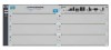
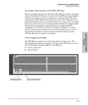
Installing the Series 5400zl Switches ProCurve Switch zl Power Supply Shelf J8714A PoE Power Fault Installing the Series 5400zl Switches Installation Procedures Operating Characteristics of the two EPS ports depending on which is on the front and back of the ...
Installing the Series 5400zl Switches ProCurve Switch zl Power Supply Shelf J8714A PoE Power Fault Installing the Series 5400zl Switches Installation Procedures Operating Characteristics of the two EPS ports depending on which is on the front and back of the ...

User Manual
Page 62
... Power LEDs on the failed power supply. 2. Ensure the AC power supply is configured with redundant power supplies, you will blink simultaneously with the switch Fault LED indicating which power supply failed. Using either a flat-bladed or Torx T-10 screwdriver loosen the retaining screws and remove the failed power supply. Although...
... Power LEDs on the failed power supply. 2. Ensure the AC power supply is configured with redundant power supplies, you will blink simultaneously with the switch Fault LED indicating which power supply failed. Using either a flat-bladed or Torx T-10 screwdriver loosen the retaining screws and remove the failed power supply. Although...

User Manual
Page 64
... two minutes) after removing the old fan tray to be removed and replaced without removing power from the switch. To avoid contact with the switch Fault LED.
... two minutes) after removing the old fan tray to be removed and replaced without removing power from the switch. To avoid contact with the switch Fault LED.

User Manual
Page 66
... the Compact Flash when the management module is the primary non-volatile storage medium located on the management module will blink simultaneously with the switch Fault LED. This prevents inadvertent removal of pressure and push both the boot software and configuration files. Replacing Components Replacing the Management Module Compact Flash Card...
... the Compact Flash when the management module is the primary non-volatile storage medium located on the management module will blink simultaneously with the switch Fault LED. This prevents inadvertent removal of pressure and push both the boot software and configuration files. Replacing Components Replacing the Management Module Compact Flash Card...

User Manual
Page 70
...network topology contains no longer experience the problems, the new topology is important to a communication of the redundant paths is active at fault. The RJ-45 ports on the switch. Non-standard and miswired cables may cause network collisions and other network problems, and ...can be only one of half duplex 5-2 If you have a valid network topology. Common topology faults include excessive cable length and excessive repeater delays between important nodes in your network to be used for pinouts and correct cable wiring. ...
...network topology contains no longer experience the problems, the new topology is important to a communication of the redundant paths is active at fault. The RJ-45 ports on the switch. Non-standard and miswired cables may cause network collisions and other network problems, and ...can be only one of half duplex 5-2 If you have a valid network topology. Common topology faults include excessive cable length and excessive repeater delays between important nodes in your network to be used for pinouts and correct cable wiring. ...

User Manual
Page 72
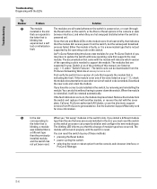
Troubleshooting Power Fault Test Module Status (one LED per module) Power (one LED per power supply) Fan Port Link Troubleshooting Diagnosing with the LEDs Diagnosing with cable 11l ...
Troubleshooting Power Fault Test Module Status (one LED per module) Power (one LED per power supply) Fan Port Link Troubleshooting Diagnosing with the LEDs Diagnosing with cable 11l ...

User Manual
Page 73
Try power cycling the switch by plugging another device into an active power source and to the switch. If the fault indication reoccurs, the switch may have failure has failed. All the services from ProCurve to get assistance. If the problem is displayed, there will be ...
Try power cycling the switch by plugging another device into an active power source and to the switch. If the fault indication reoccurs, the switch may have failure has failed. All the services from ProCurve to get assistance. If the problem is displayed, there will be ...
User Manual
Page 74
...indicate which version of the operating code is blinking has experienced a self test or initialization fault. The modules that is reinstalled, it will not work properly until the switch is indicating the fault. Either the module is faulty, or it with another module, or recover the slot... removing and reinstalling the module. blinking, a module The blinking LED informs you must reset the switch the letter that is reset. If the fault indication reoccurs, the module may have to see what version of these methods: • pressing the Reset button. • power cycling the ...
...indicate which version of the operating code is blinking has experienced a self test or initialization fault. The modules that is reinstalled, it will not work properly until the switch is indicating the fault. Either the module is faulty, or it with another module, or recover the slot... removing and reinstalling the module. blinking, a module The blinking LED informs you must reset the switch the letter that is reset. If the fault indication reoccurs, the module may have to see what version of these methods: • pressing the Reset button. • power cycling the ...

User Manual
Page 75
... seconds per cycle. configured on the switch and a security violation has been detected on a port, the switch will operate normally. ➑ A fault condition Try removing and reinstalling the power supply. If the port is a mini-GBIC, verify it is one or more information on the module, which... the Link LED is disconnected from ProCurve number. If the port fault indication reoccurs, and you will be identified with the LEDs Tip Number ➐ Problem The network port for best operation, the switch should...
... seconds per cycle. configured on the switch and a security violation has been detected on a port, the switch will operate normally. ➑ A fault condition Try removing and reinstalling the power supply. If the port is a mini-GBIC, verify it is one or more information on the module, which... the Link LED is disconnected from ProCurve number. If the port fault indication reoccurs, and you will be identified with the LEDs Tip Number ➐ Problem The network port for best operation, the switch should...

User Manual
Page 78
... 2-26. Neither of these LEDs stay on the front of modules installed in the switch. Checking the Switch LEDs The self-test passes if the Fault and Test LEDs on interpreting the LED patterns. Then, when you can reset the switch to test its power-on self-test, which almost always...
... 2-26. Neither of these LEDs stay on the front of modules installed in the switch. Checking the Switch LEDs The self-test passes if the Fault and Test LEDs on interpreting the LED patterns. Then, when you can reset the switch to test its power-on self-test, which almost always...

User Manual
Page 113
...Gigabit-SX ports, cables used with ... B-3 flash memory replacing PCMCIA card ... 4-5, 4-6 front of ... 1-6 error indications ... 5-4 Fan Status ... 1-6, 1-7 showing error conditions ... 5-4 Fault ... 1-6 behavior during troubleshooting ... 5-10 descriptions of switch Clear button ... 1-10 console port ... 1-10 description ... 1-5 LEDs ... 1-6 Mode Select button and indicator LEDs ... 1-9 Reset... ... 2-7 summary of steps ... 2-3 IP address configuring ... 3-3 using for new module type ... 2-28 switch modules ... 2-28 HP Auto-MDIX feature description ... B-3 1000Base-LH ...
...Gigabit-SX ports, cables used with ... B-3 flash memory replacing PCMCIA card ... 4-5, 4-6 front of ... 1-6 error indications ... 5-4 Fan Status ... 1-6, 1-7 showing error conditions ... 5-4 Fault ... 1-6 behavior during troubleshooting ... 5-10 descriptions of switch Clear button ... 1-10 console port ... 1-10 description ... 1-5 LEDs ... 1-6 Mode Select button and indicator LEDs ... 1-9 Reset... ... 2-7 summary of steps ... 2-3 IP address configuring ... 3-3 using for new module type ... 2-28 switch modules ... 2-28 HP Auto-MDIX feature description ... B-3 1000Base-LH ...

User Manual
Page 115
... used with the switch ... 2-7 of Reset button ... 1-10 troubleshooting procedure ... 5-10 routing features ... 1-14 S safety and regulatory statements ... A-3 selecting the Mode LED display ... 1-9 self test Fault LED behavior ... 2-16 LED behavior during ... 2-16 Power LED behavior ... 2-16 Self Test LED behavior ... 2-16 Self Test LED behavior during factory default reset ... 5-12...
... used with the switch ... 2-7 of Reset button ... 1-10 troubleshooting procedure ... 5-10 routing features ... 1-14 S safety and regulatory statements ... A-3 selecting the Mode LED display ... 1-9 self test Fault LED behavior ... 2-16 LED behavior during ... 2-16 Power LED behavior ... 2-16 Self Test LED behavior ... 2-16 Self Test LED behavior during factory default reset ... 5-12...