
User Manual
Page 6
...Address for Remote Switch Management 3-5 Starting a Telnet Session 3-5 Starting a Web Browser Session 3-5 4 Troubleshooting Basic Troubleshooting Tips 4-1 Diagnosing with the LEDs 4-4 Proactive Networking 4-8 Hardware Diagnostic Tests 4-9 Testing the Switch by Resetting It 4-9 Checking the Switch LEDs 4-9 Checking Console Messages 4-9 Testing Twisted-Pair Cabling 4-10 Testing Switch-to-Device Network Communications 4-10 Testing End-to-End Network Communications 4-10 Restoring the Factory Default Configuration 4-11 Downloading New Switch Software 4-12 HP Customer Support Services...
...Address for Remote Switch Management 3-5 Starting a Telnet Session 3-5 Starting a Web Browser Session 3-5 4 Troubleshooting Basic Troubleshooting Tips 4-1 Diagnosing with the LEDs 4-4 Proactive Networking 4-8 Hardware Diagnostic Tests 4-9 Testing the Switch by Resetting It 4-9 Checking the Switch LEDs 4-9 Checking Console Messages 4-9 Testing Twisted-Pair Cabling 4-10 Testing Switch-to-Device Network Communications 4-10 Testing End-to-End Network Communications 4-10 Restoring the Factory Default Configuration 4-11 Downloading New Switch Software 4-12 HP Customer Support Services...

User Manual
Page 7
... Support 4-12 A Switch Specifications Physical A-1 Electrical A-1 Environmental A-1 Acoustic A-2 Connectors A-2 Safety A-2 Lasers A-2 B Switch Ports and Network Cables Switch Ports B-1 Twisted-Pair Cables B-1 Mode Conditioning Patch Cord for Gigabit-LX B-3 Installing the Patch Cord B-4 Recommended Patch Cords B-4 Twisted-Pair Cable/Connector Pin-Outs B-5 Straight-Through Twisted-Pair Cable for 10 Mbps or 100 Mbps Network Connections B-6 Cable Diagram B-6 Pin Assignments B-6 Crossover Twisted-Pair Cable for 10 Mbps or 100 Mbps Network Connection B-7 Cable Diagram B-7 Pin...
... Support 4-12 A Switch Specifications Physical A-1 Electrical A-1 Environmental A-1 Acoustic A-2 Connectors A-2 Safety A-2 Lasers A-2 B Switch Ports and Network Cables Switch Ports B-1 Twisted-Pair Cables B-1 Mode Conditioning Patch Cord for Gigabit-LX B-3 Installing the Patch Cord B-4 Recommended Patch Cords B-4 Twisted-Pair Cable/Connector Pin-Outs B-5 Straight-Through Twisted-Pair Cable for 10 Mbps or 100 Mbps Network Connections B-6 Cable Diagram B-6 Pin Assignments B-6 Crossover Twisted-Pair Cable for 10 Mbps or 100 Mbps Network Connection B-7 Cable Diagram B-7 Pin...

User Manual
Page 13
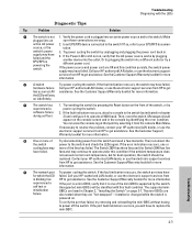
... light. Otherwise, the port may have been disabled through the switch console or the web browser interface. • if the port LED is blinking, the switch could be attached to an RPS but not receiving power. If just the Fault LED is blinking* simultaneously with the port number) Displays port link information, network activity information, whether the port is not undergoing self test. (green) On The switch self test and initialization are no active network cable connected...
... light. Otherwise, the port may have been disabled through the switch console or the web browser interface. • if the port LED is blinking, the switch could be attached to an RPS but not receiving power. If just the Fault LED is blinking* simultaneously with the port number) Displays port link information, network activity information, whether the port is not undergoing self test. (green) On The switch self test and initialization are no active network cable connected...
User Manual
Page 16
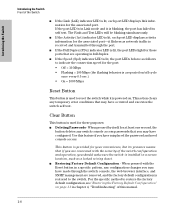
...) indicator LED is blinking, the port has failed its presence means that you may have misplaced the password and need console access. This button is provided for your convenience, but its self test. When pressed with the security of the switch configuration and operation, you should make sure the switch is installed in a specific pattern, any temporary error conditions that are removed, and the factory default configuration is powered on page...
...) indicator LED is blinking, the port has failed its presence means that you may have misplaced the password and need console access. This button is provided for your convenience, but its self test. When pressed with the security of the switch configuration and operation, you should make sure the switch is installed in a specific pattern, any temporary error conditions that are removed, and the factory default configuration is powered on page...

User Manual
Page 18
...-over cables are enabled-just connect the network cables to manage your business needs. ■ support for many advanced features to the port, it configures the port as MDI; if the switch detects that an end-node device is connected to the port, it configures the port as MDI-X. ■ automatic learning of the network addresses in graphical interface that can be accessed from common web browsers. • HP ProCurve Manager-an SNMP based, graphical network managent...
...-over cables are enabled-just connect the network cables to manage your business needs. ■ support for many advanced features to the port, it configures the port as MDI; if the switch detects that an end-node device is connected to the port, it configures the port as MDI-X. ■ automatic learning of the network addresses in graphical interface that can be accessed from common web browsers. • HP ProCurve Manager-an SNMP based, graphical network managent...

User Manual
Page 21
... point, the switch is fully installed. Connect power to the switch's console port. Configuration changes can be made easily by using the included console cable to connect a PC to the switch (page 2-17). Verify the switch passes self test (page 2-9). Connect the network cables (page 2-18). Note that the LEDs on . 3. Once the switch is mounted, plug it into a power source and observing that mini-GBICs can be hot swapped-they can be installed or removed...
... point, the switch is fully installed. Connect power to the switch's console port. Configuration changes can be made easily by using the included console cable to connect a PC to the switch (page 2-17). Verify the switch passes self test (page 2-9). Connect the network cables (page 2-18). Note that the LEDs on . 3. Once the switch is mounted, plug it into a power source and observing that mini-GBICs can be hot swapped-they can be installed or removed...

User Manual
Page 25
Installing or Removing mini-GBICs You can install or remove a mini-GBIC from the transmit port. Use only HP ProCurve mini-GBICs. ■ The mini-GBIC slots are Class 1 laser devices. Half duplex operation is not supported. ■ Ensure the network cable is disabled and cannot be used. ■ The mini-GBIC ports operate only at full duplex. Installing the Switch Notes Caution Installing the Switch Installation Procedures 2. Installing the mini-GBICs...
Installing or Removing mini-GBICs You can install or remove a mini-GBIC from the transmit port. Use only HP ProCurve mini-GBICs. ■ The mini-GBIC slots are Class 1 laser devices. Half duplex operation is not supported. ■ Ensure the network cable is disabled and cannot be used. ■ The mini-GBIC ports operate only at full duplex. Installing the Switch Notes Caution Installing the Switch Installation Procedures 2. Installing the mini-GBICs...

User Manual
Page 36
... connected device, the Link LED for the port should light to confirm a powered-on device (for example, an end node) is connected to the port, the port LED for all the switch ports, when a network cable from the network devices or your patch panels to the fixed RJ-45 ports on the switch or to the port, see "Diagnosing with the LEDs" on page 4-4 in chapter 4, "Troubleshooting". 2-18 See the table on page 2-6, and appendix B, "Switch Ports and Network Cables...
... connected device, the Link LED for the port should light to confirm a powered-on device (for example, an end node) is connected to the port, the port LED for all the switch ports, when a network cable from the network devices or your patch panels to the fixed RJ-45 ports on the switch or to the port, see "Diagnosing with the LEDs" on page 4-4 in chapter 4, "Troubleshooting". 2-18 See the table on page 2-6, and appendix B, "Switch Ports and Network Cables...

User Manual
Page 40
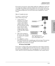
... IP addressing and on starting a Telnet session, see chapter 3, "Configuring the Switch", and the Management and Configuration Guide, which is on the network, and a VT-100 terminal emulator. Installing the Switch Installing the Switch Installation Procedures 8. (Optional) Connect a Console to the Switch The switch has a full-featured, easy to use a VT-100 terminal, and configure either one in troubleshooting ■ Download new software to the switch ■ Add passwords to control access to the switch from the console, web browser interface, and network management...
... IP addressing and on starting a Telnet session, see chapter 3, "Configuring the Switch", and the Management and Configuration Guide, which is on the network, and a VT-100 terminal emulator. Installing the Switch Installing the Switch Installation Procedures 8. (Optional) Connect a Console to the Switch The switch has a full-featured, easy to use a VT-100 terminal, and configure either one in troubleshooting ■ Download new software to the switch ■ Add passwords to control access to the switch from the console, web browser interface, and network management...
User Manual
Page 41
...-pin serial connector, first attach a 9-pin to 25-pin straight-through adapter at this time, see chapter 3, "Configuring the Switch" for example: HP ProCurve Switch 2848# If you change the terminal settings, then reboot the switch and reestablish the console session. Console port Console cable supplied with console management of the switch at one end of the console cable.) 2. For more detailed information, refer to the Management and Configuration Guide, which is on the Switch 2824 is in front. 3. Turn on the switch so...
...-pin serial connector, first attach a 9-pin to 25-pin straight-through adapter at this time, see chapter 3, "Configuring the Switch" for example: HP ProCurve Switch 2848# If you change the terminal settings, then reboot the switch and reestablish the console session. Console port Console cable supplied with console management of the switch at one end of the console cable.) 2. For more detailed information, refer to the Management and Configuration Guide, which is on the Switch 2824 is in front. 3. Turn on the switch so...

User Manual
Page 49
... on using the console Switch Setup screen to quickly assign an IP (Internet Protocol) address and subnet mask to improve network security. Also, you should configure the switch with an IP address and subnet mask compatible with values you can be managed only through the switch's web browser interface, and from the console and web browser interface. For more conveniently through a remote Telnet session, through a direct console connection. For a listing of the network traffic, and to the switch, set a Manager password...
... on using the console Switch Setup screen to quickly assign an IP (Internet Protocol) address and subnet mask to improve network security. Also, you should configure the switch with an IP address and subnet mask compatible with values you can be managed only through the switch's web browser interface, and from the console and web browser interface. For more conveniently through a remote Telnet session, through a direct console connection. For a listing of the network traffic, and to the switch, set a Manager password...

User Manual
Page 51
... Set to Manual unless a DHCP/Bootp server is used in your network. up to Manual, then enter an IP address compatible with your network. Community Name public Default setting recommended. If you set IP Config to 16 characters (no blank spaces) Logon Default CLI The default setting selects the command line interface for Save). Configuring the Switch 3-3 up to configure IP addressing. Default Gateway blank Optional; TimeP Mode Disabled Optional; For more information on IP addressing, see the Management and Configuration Guide...
... Set to Manual unless a DHCP/Bootp server is used in your network. up to Manual, then enter an IP address compatible with your network. Community Name public Default setting recommended. If you set IP Config to 16 characters (no blank spaces) Logon Default CLI The default setting selects the command line interface for Save). Configuring the Switch 3-3 up to configure IP addressing. Default Gateway blank Optional; TimeP Mode Disabled Optional; For more information on IP addressing, see the Management and Configuration Guide...

User Manual
Page 56
... should enable Spanning Tree Protocol support on the switch. For more information on Spanning Tree and Trunking, see the Management and Configuration Guide, which allows multiple network cables to be enabled through the switch console or the web browser interface. If that came with the IEEE 802.3 standard), if a device connected to the switch has a fixed configuration at half duplex (all devices connected to the Switch 2800 Series devices are configured to auto negotiate, or are configured this...
... should enable Spanning Tree Protocol support on the switch. For more information on Spanning Tree and Trunking, see the Management and Configuration Guide, which allows multiple network cables to be enabled through the switch console or the web browser interface. If that came with the IEEE 802.3 standard), if a device connected to the switch has a fixed configuration at half duplex (all devices connected to the Switch 2800 Series devices are configured to auto negotiate, or are configured this...
User Manual
Page 59
... console log identifying the error condition. If the fault indication reoccurs, the switch may have failed. All assistance. Then, reset the switch. Then reconnect the power to the switch? experienced a self test or initialization failure. Unsupported mini-GBICs will have for which the LED failed. If so, refer to your HP-authorized LAN dealer, or use the electronic support services from HP to replace the mini-GBIC. switch's power supply may have to get...
... console log identifying the error condition. If the fault indication reoccurs, the switch may have failed. All assistance. Then, reset the switch. Then reconnect the power to the switch? experienced a self test or initialization failure. Unsupported mini-GBICs will have for which the LED failed. If so, refer to your HP-authorized LAN dealer, or use the electronic support services from HP to replace the mini-GBIC. switch's power supply may have to get...

User Manual
Page 60
... (ELFEXT), Multiple Disturber ELFEXT, and Return Loss. Cable testing should be a very unreliable connection, or no link at the switch and the connected working device, are both powered on and operating correctly. • Verify you have used because of the switch's Auto MDI/MDI-X feature of the 10/100/1000-T port. Note: If the switch port configuration is not installed in the cabling path. • Verify that the network cabling complies...
... (ELFEXT), Multiple Disturber ELFEXT, and Return Loss. Cable testing should be a very unreliable connection, or no link at the switch and the connected working device, are both powered on and operating correctly. • Verify you have used because of the switch's Auto MDI/MDI-X feature of the 10/100/1000-T port. Note: If the switch port configuration is not installed in the cabling path. • Verify that the network cabling complies...
User Manual
Page 63
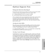
... begin blinking, there may be reset to zero, and cause the System Up Time timer to reset to test its power-on the front of the switch Power cycling the switch and pressing the Reset button both cause the switch to run at 9600 baud, and with the switch. Checking Console Messages Useful diagnostic messages may be accessed from the console using the show log command, or from the console Main Menu. 4-9 Troubleshooting...
... begin blinking, there may be reset to zero, and cause the System Up Time timer to reset to test its power-on the front of the switch Power cycling the switch and pressing the Reset button both cause the switch to run at 9600 baud, and with the switch. Checking Console Messages Useful diagnostic messages may be accessed from the console using the show log command, or from the console Main Menu. 4-9 Troubleshooting...
User Manual
Page 65
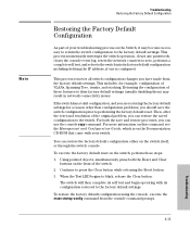
... the console command prompt. 4-11 Troubleshooting When the Test LED begins to press the Clear button while releasing the Reset button. 3. For both the Reset and Clear buttons on the switch itself, or through the switch console. This process momentarily interrupts the switch operation, clears any passwords, clears the console event log, resets the network counters to the factory default settings. This includes, for a reason other than configuration problems, you can use the console copy command. The switch will then complete its factory default configuration...
... the console command prompt. 4-11 Troubleshooting When the Test LED begins to press the Clear button while releasing the Reset button. 3. For both the Reset and Clear buttons on the switch itself, or through the switch console. This process momentarily interrupts the switch operation, clears any passwords, clears the console event log, resets the network counters to the factory default settings. This includes, for a reason other than configuration problems, you can use the console copy command. The switch will then complete its factory default configuration...

User Manual
Page 66
.... Troubleshooting Downloading New Switch Software Downloading New Switch Software When product enhancements occur for the Switch 2800 Series devices, new software can provide you are still having trouble with your switch. See the Customer Support/Warranty booklet that came with services offered by HP. Additionally, your HP-authorized network reseller can be available on the GBICs mini-GBICs • details about the switch's status including the software (OS) version, a copy of the switch configuration...
.... Troubleshooting Downloading New Switch Software Downloading New Switch Software When product enhancements occur for the Switch 2800 Series devices, new software can provide you are still having trouble with your switch. See the Customer Support/Warranty booklet that came with services offered by HP. Additionally, your HP-authorized network reseller can be available on the GBICs mini-GBICs • details about the switch's status including the software (OS) version, a copy of the switch configuration...
User Manual
Page 88
... default configuration,restoring ... 1-8 Fan Status LED ... 1-6 Fault LED ... 1-5 behavior during troubleshooting ... 4-9 displaying the CLI prompt ... 2-23 features ... 2-22 how to connect in -band access ... 2-22 diagnostic tests ... 4-9 checking the console messages ... 4-9 checking the LEDs ... 4-9 end-to-end connectivity ... 4-10 testing the switch only ... 4-9 testing twisted-pair cabling ... 4-10 downloading new switch software ... 4-12 dual-personality ports LEDs ... 1-6 location on switch ... 1-4 operation description ... 1-4 E electrical specifications, switch ... Clear button...
... default configuration,restoring ... 1-8 Fan Status LED ... 1-6 Fault LED ... 1-5 behavior during troubleshooting ... 4-9 displaying the CLI prompt ... 2-23 features ... 2-22 how to connect in -band access ... 2-22 diagnostic tests ... 4-9 checking the console messages ... 4-9 checking the LEDs ... 4-9 end-to-end connectivity ... 4-10 testing the switch only ... 4-9 testing twisted-pair cabling ... 4-10 downloading new switch software ... 4-12 dual-personality ports LEDs ... 1-6 location on switch ... 1-4 operation description ... 1-4 E electrical specifications, switch ... Clear button...

User Manual
Page 90
... pin-outs twisted-pair cables ... Index ports 10/100Base-TX, location on switch ... 1-3 connecting to ... 2-18 location on switch ... 1-3, 1-8 restoring factory default configuration ... 4-11 resetting the switch factory default reset ... 4-11 location of -band console access ... 3-5 P parts, included with the switch ... 2-1 password configuring ... 3-2 passwords deleting with ... 4-8 R rack mounting precautions ... 2-4 mounting the switch in ... 2-11 Redundant Power Supply ... 2-19 regulatory statements ... B-5 network devices connecting to the switch ... 2-18 network ports connecting...
... pin-outs twisted-pair cables ... Index ports 10/100Base-TX, location on switch ... 1-3 connecting to ... 2-18 location on switch ... 1-3, 1-8 restoring factory default configuration ... 4-11 resetting the switch factory default reset ... 4-11 location of -band console access ... 3-5 P parts, included with the switch ... 2-1 password configuring ... 3-2 passwords deleting with ... 4-8 R rack mounting precautions ... 2-4 mounting the switch in ... 2-11 Redundant Power Supply ... 2-19 regulatory statements ... B-5 network devices connecting to the switch ... 2-18 network ports connecting...


