

User Manual
Page 5
... 2-18 Connecting Cables to a Power Source 2-17 6. Contents 1 Introducing the Switch Front of the Switch 1-3 Network Ports 1-3 LEDs 1-5 LED Mode Select Button and Indicator LEDs 1-7 Reset Button 1-8 Clear Button 1-8 Back of the Switch 1-9 Console Port 1-9 Power Connector 1-9 Switch Features 1-10 2 Installing the Switch Included Parts 2-1 Installation Procedures 2-3 Summary 2-3 Installation Precautions 2-4 1. Verify...
... 2-18 Connecting Cables to a Power Source 2-17 6. Contents 1 Introducing the Switch Front of the Switch 1-3 Network Ports 1-3 LEDs 1-5 LED Mode Select Button and Indicator LEDs 1-7 Reset Button 1-8 Clear Button 1-8 Back of the Switch 1-9 Console Port 1-9 Power Connector 1-9 Switch Features 1-10 2 Installing the Switch Included Parts 2-1 Installation Procedures 2-3 Summary 2-3 Installation Precautions 2-4 1. Verify...
User Manual
Page 6
... Management 3-5 Starting a Telnet Session 3-5 Starting a Web Browser Session 3-5 4 Troubleshooting Basic Troubleshooting Tips 4-1 Diagnosing with the LEDs 4-4 Proactive Networking 4-8 Hardware Diagnostic Tests 4-9 Testing the Switch by Resetting It 4-9 Checking the Switch LEDs 4-9 Checking Console Messages 4-9 Testing Twisted-Pair Cabling 4-10 Testing Switch-to-Device Network Communications 4-10 Testing End-to-End Network...
... Management 3-5 Starting a Telnet Session 3-5 Starting a Web Browser Session 3-5 4 Troubleshooting Basic Troubleshooting Tips 4-1 Diagnosing with the LEDs 4-4 Proactive Networking 4-8 Hardware Diagnostic Tests 4-9 Testing the Switch by Resetting It 4-9 Checking the Switch LEDs 4-9 Checking Console Messages 4-9 Testing Twisted-Pair Cabling 4-10 Testing Switch-to-Device Network Communications 4-10 Testing End-to-End Network...
User Manual
Page 9
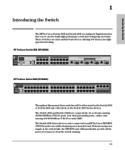
... 40 41 42 43 44 switch 2848 1 15 17 31 33 43 J4904A Power Fault Status LED Lnk RPS Mode Act Fan FDx Test Spd Reset Clear Spd mode: off = 10 Mbps, flash = 100 Mbps, on = 1000 Mbps 16 18 10/100/1000Base-T Ports (1 - 44, 45T, 46T, 47T, 48T) — Ports...-sensing 10/100/1000Base-T RJ-45 ports, four dual-personality ports-either autosensing 10/100/1000Base-T RJ-45 or mini-GBIC. HP ProCurve Switch 2824 (HPJ4903A) Power Fault hp procurve switch 2824 J4903A 12345678 9 10 11 12 13 14 15 16 17 18 19 20 1 79 19 Dual-Personality Ports: 10/100/1000...
... 40 41 42 43 44 switch 2848 1 15 17 31 33 43 J4904A Power Fault Status LED Lnk RPS Mode Act Fan FDx Test Spd Reset Clear Spd mode: off = 10 Mbps, flash = 100 Mbps, on = 1000 Mbps 16 18 10/100/1000Base-T Ports (1 - 44, 45T, 46T, 47T, 48T) — Ports...-sensing 10/100/1000Base-T RJ-45 ports, four dual-personality ports-either autosensing 10/100/1000Base-T RJ-45 or mini-GBIC. HP ProCurve Switch 2824 (HPJ4903A) Power Fault hp procurve switch 2824 J4903A 12345678 9 10 11 12 13 14 15 16 17 18 19 20 1 79 19 Dual-Personality Ports: 10/100/1000...
User Manual
Page 11
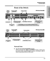
... and RPS Status LEDs Switch port LEDs HP ProCurve Switch 2824 Power Fault hp procurve switch 2824 J4903A 12345678 9 10 11 12 13 14 ...15 16 17 18 19 20 1 79 19 Dual-Personality Ports: 10/100/1000-T (T) or Mini-GBIC (M) — T ports are IEEE Auto MDI/MDI-X 32 34 T 45 M T 46 M T 47 M T 48 M 44 Dual-Personality Ports: 10/100/1000-T (T) or Mini-GBIC (M) Reset...100/1000Base-T RJ-45 ports* Dual-personality ports (10/100/1000Base-T* or mini-GBIC) Reset and Clear buttons * 10/100/1000Base-T ports have the "IEEE Auto MDI/MDI-X" ...
... and RPS Status LEDs Switch port LEDs HP ProCurve Switch 2824 Power Fault hp procurve switch 2824 J4903A 12345678 9 10 11 12 13 14 ...15 16 17 18 19 20 1 79 19 Dual-Personality Ports: 10/100/1000-T (T) or Mini-GBIC (M) — T ports are IEEE Auto MDI/MDI-X 32 34 T 45 M T 46 M T 47 M T 48 M 44 Dual-Personality Ports: 10/100/1000-T (T) or Mini-GBIC (M) Reset...100/1000Base-T RJ-45 ports* Dual-personality ports (10/100/1000Base-T* or mini-GBIC) Reset and Clear buttons * 10/100/1000Base-T ports have the "IEEE Auto MDI/MDI-X" ...

User Manual
Page 13
...link information, network activity information, whether the port is configured for more information. See "LED Mode Select Button and Indicator LEDs" on or reset, at 1000 Mbps. * The blinking behavior is not receiving link beat or sufficient light. FDx Indicates port LEDs are no active network ... continuously, the port is blinking* simultaneously with the fault will blink simultaneously. On On briefly after the switch has been power cycled or reset . See chapter 4, "Troubleshooting" for fullduplex operation, or the speed of the switch ports, or the fan. The status LED for ...
...link information, network activity information, whether the port is configured for more information. See "LED Mode Select Button and Indicator LEDs" on or reset, at 1000 Mbps. * The blinking behavior is not receiving link beat or sufficient light. FDx Indicates port LEDs are no active network ... continuously, the port is blinking* simultaneously with the fault will blink simultaneously. On On briefly after the switch has been power cycled or reset . See chapter 4, "Troubleshooting" for fullduplex operation, or the speed of the switch ports, or the fan. The status LED for ...
User Manual
Page 15
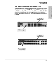
... the switch ports without overwhelming you with LEDs, the Switch 2800 Series devices use a single LED for each port) hp procurve 1 2 3 4 5 6 7 8 9 10 11 12 13 14 15 16 17 18 19 20 ...21 22 23 switch 2848 1 15 17 J4904A Power Fault Status LED Lnk RPS Mode Act Fan FDx Test Spd Reset Clear Spd mode: off = 10 Mbps, flash = 100 Mbps, on = 1000 Mbps 10/100/1000-T Ports ...port) Power Fault hp procurve switch 2824 12345678 9 10 11 12 13 14 15 16 17 18 19 20 1 79 19 Dual-Person J4903A Console Status LED Lnk 21 RPS Mode Act Fan FDx T Test Spd M Reset Clear Spd mode...
... the switch ports without overwhelming you with LEDs, the Switch 2800 Series devices use a single LED for each port) hp procurve 1 2 3 4 5 6 7 8 9 10 11 12 13 14 15 16 17 18 19 20 ...21 22 23 switch 2848 1 15 17 J4904A Power Fault Status LED Lnk RPS Mode Act Fan FDx Test Spd Reset Clear Spd mode: off = 10 Mbps, flash = 100 Mbps, on = 1000 Mbps 10/100/1000-T Ports ...port) Power Fault hp procurve switch 2824 12345678 9 10 11 12 13 14 15 16 17 18 19 20 1 79 19 Dual-Person J4903A Console Status LED Lnk 21 RPS Mode Act Fan FDx T Test Spd M Reset Clear Spd mode...
User Manual
Page 16
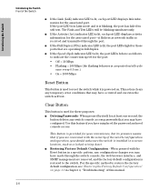
... configuration and operation, you should make sure the switch is installed in a secure location, such as follows to the switch. When pressed with the Reset button in Link mode and it is restored to indicate the connection speed for the port: • Off = 10 Mbps • Flashing = ...100 Mbps (the flashing behavior is a repeated on/off cycle once every 0.5 sec.) • On = 1000 Mbps Reset Button This button is used for your convenience, but its presence means that if you have configured. This action clears any switch console access passwords...
... configuration and operation, you should make sure the switch is installed in a secure location, such as follows to the switch. When pressed with the Reset button in Link mode and it is restored to indicate the connection speed for the port: • Off = 10 Mbps • Flashing = ...100 Mbps (the flashing behavior is a repeated on/off cycle once every 0.5 sec.) • On = 1000 Mbps Reset Button This button is used for your convenience, but its presence means that if you have configured. This action clears any switch console access passwords...
User Manual
Page 28
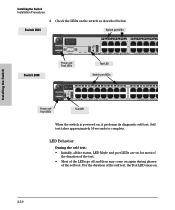
Switch 2824 Switch port LEDs Power Fault hp procurve switch 2824 J4903A Console 12345678 9 10 11 12 13 14 15 16 1 1 79 Reset Clear Status LED Lnk RPS Mode Act Fan FDx Test Spd Spd mode: off = ...all the status, LED Mode and port LEDs are IEEE A Switch 2848 Power and Fault LEDs Test LED Switch port LEDs Power Fault hp procurve 1 2 3 4 5 6 7 8 9 10 11 12 13 14 15 16 17 18 19 20 21 22 23 ...24 25 switch 2848 1 15 17 J4904A Status LED Lnk RPS Mode Act Fan FDx Test Spd Reset Clear Spd mode: off and then may come on the switch as described below. Check the LEDs ...
Switch 2824 Switch port LEDs Power Fault hp procurve switch 2824 J4903A Console 12345678 9 10 11 12 13 14 15 16 1 1 79 Reset Clear Status LED Lnk RPS Mode Act Fan FDx Test Spd Spd mode: off = ...all the status, LED Mode and port LEDs are IEEE A Switch 2848 Power and Fault LEDs Test LED Switch port LEDs Power Fault hp procurve 1 2 3 4 5 6 7 8 9 10 11 12 13 14 15 16 17 18 19 20 21 22 23 ...24 25 switch 2848 1 15 17 J4904A Status LED Lnk RPS Mode Act Fan FDx Test Spd Reset Clear Spd mode: off and then may come on the switch as described below. Check the LEDs ...
User Manual
Page 45
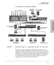
...Backbone Switch To IT or Data Center PCs, local servers, and Server with Gigabit Ethernet NIC HP ProCurve Switch 2848 Power Fault hp procurve switch 5304xl J4850A Console Link 1 1 J4878A Mode Power Status Fault 1 2 A B C D E F G H Reset Clear Self Fan Power Modules Test Act FDx Max ! LED Mode Select Use xl modules ...local servers, and peripherals Server with Gigabit peripherals Ethernet NIC Installing the Switch Power Fault hp procurve switch 5304xl J4850A Console Link 1 1 J4878A Mode Status 1 2 ABCDEF GH Reset Clear Self Fan Power Modules Test Act FDx Max !
...Backbone Switch To IT or Data Center PCs, local servers, and Server with Gigabit Ethernet NIC HP ProCurve Switch 2848 Power Fault hp procurve switch 5304xl J4850A Console Link 1 1 J4878A Mode Power Status Fault 1 2 A B C D E F G H Reset Clear Self Fan Power Modules Test Act FDx Max ! LED Mode Select Use xl modules ...local servers, and peripherals Server with Gigabit peripherals Ethernet NIC Installing the Switch Power Fault hp procurve switch 5304xl J4850A Console Link 1 1 J4878A Mode Status 1 2 ABCDEF GH Reset Clear Self Fan Power Modules Test Act FDx Max !
User Manual
Page 47
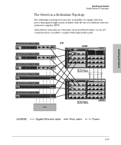
... Mode 1 module J4821A G 1 Link Mode 1 J4821A 100/1000Base-T Ports 2 3 4 2 STP 3 4 100/1000Base-T Ports 2 2 3 3 4 4 F xl module H xl module HP ProCurve Switch 5308xl Power Fault hp procurve switch 5308xl J4819A Console Link 1 1 J4878A Mode Status 1 2 ABCDEF GH Reset Clear Self Fan Power Modules Test Act FDxMax ! Installing the Switch Installing the Switch Sample Network Topologies...
... Mode 1 module J4821A G 1 Link Mode 1 J4821A 100/1000Base-T Ports 2 3 4 2 STP 3 4 100/1000Base-T Ports 2 2 3 3 4 4 F xl module H xl module HP ProCurve Switch 5308xl Power Fault hp procurve switch 5308xl J4819A Console Link 1 1 J4878A Mode Status 1 2 ABCDEF GH Reset Clear Self Fan Power Modules Test Act FDxMax ! Installing the Switch Installing the Switch Sample Network Topologies...
User Manual
Page 59
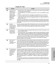
.... hardware failure Call your HP-authorized LAN dealer, or use the electronic support services from HP to get assistance. If the fault indication reoccurs, attach a console to get assistance. Then, reset the switch. If necessary to resolve the problem, contact your HP-authorized LAN dealer, or... use the electronic support services from HP to the switch (as indicated in the console log identifying the error ...
.... hardware failure Call your HP-authorized LAN dealer, or use the electronic support services from HP to get assistance. If the fault indication reoccurs, attach a console to get assistance. Then, reset the switch. If necessary to resolve the problem, contact your HP-authorized LAN dealer, or... use the electronic support services from HP to the switch (as indicated in the console log identifying the error ...
User Manual
Page 63
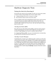
...test its power-on self test, which can check the switch event log, which almost always will resolve any temporary operational problems. These reset processes also cause any network traffic counters to perform its circuitry and operating code. Checking Console Messages Useful diagnostic messages may be a ... the LEDs" on page 4-4 for information on interpreting the LED patterns and LED behaviors in the power cord (power cycling) ■ Press the Reset button on page 2-22. To connect a PC running a VT-100 terminal emulator program or a standard VT-100 terminal to the switch's Console ...
...test its power-on self test, which can check the switch event log, which almost always will resolve any temporary operational problems. These reset processes also cause any network traffic counters to perform its circuitry and operating code. Checking Console Messages Useful diagnostic messages may be a ... the LEDs" on page 4-4 for information on interpreting the LED patterns and LED behaviors in the power cord (power cycling) ■ Press the Reset button on page 2-22. To connect a PC running a VT-100 terminal emulator program or a standard VT-100 terminal to the switch's Console ...
User Manual
Page 65
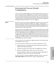
...see the Management and Configuration Guide, which is configured. When the Test LED begins to press the Clear button while releasing the Reset button. 3. Returning the configuration of these steps: 1. Using pointed objects, simultaneously press both the save the switch configuration prior to...configuration problems, you should save and restore processes, you have made from the console command prompt. 4-11 Troubleshooting For both the Reset and Clear buttons on the switch, perform these features to their factory default settings (usually disabling them) may become necessary to...
...see the Management and Configuration Guide, which is configured. When the Test LED begins to press the Clear button while releasing the Reset button. 3. Returning the configuration of these steps: 1. Using pointed objects, simultaneously press both the save the switch configuration prior to...configuration problems, you should save and restore processes, you have made from the console command prompt. 4-11 Troubleshooting For both the Reset and Clear buttons on the switch, perform these features to their factory default settings (usually disabling them) may become necessary to...
User Manual
Page 87
...-over cable pin-out ... B-7 pin-outs ... B-2 infrastructure requirements ... 2-5 length limitations ... 2-5 required types ... 2-5 serial, for in-band access ... 2-22 buttons Clear button ... 1-8 LED Mode select button ... 1-7 Reset button ... 1-8 C cabinet mounting the switch in ... 2-11 cables 1000Base-LH connections ... 2-6 fiber-optic cable specifications ... B-6, B-8 switch-to-switch or hub connection ... B-5 wiring rules ...
...-over cable pin-out ... B-7 pin-outs ... B-2 infrastructure requirements ... 2-5 length limitations ... 2-5 required types ... 2-5 serial, for in-band access ... 2-22 buttons Clear button ... 1-8 LED Mode select button ... 1-7 Reset button ... 1-8 C cabinet mounting the switch in ... 2-11 cables 1000Base-LH connections ... 2-6 fiber-optic cable specifications ... B-6, B-8 switch-to-switch or hub connection ... B-5 wiring rules ...

User Manual
Page 89
... MDI network cable ... front of switch ... 1-3 10/100Base-TX ports ... 1-3 Clear button ... 1-8 description ... 1-3 dual-personality ports ... 1-4 LED Mode select button and LEDs ... 1-7 LEDs ... 1-5 network ports ... 1-3 Reset button ... 1-8 full-duplex fixed configuration effects on network connections ... 4-1 full-duplex operation of mini-GBICs ... 2-7 H horizontal surface mounting switch on ... 2-17 I in-band ... 3-1 in a rack...
... MDI network cable ... front of switch ... 1-3 10/100Base-TX ports ... 1-3 Clear button ... 1-8 description ... 1-3 dual-personality ports ... 1-4 LED Mode select button and LEDs ... 1-7 LEDs ... 1-5 network ports ... 1-3 Reset button ... 1-8 full-duplex fixed configuration effects on network connections ... 4-1 full-duplex operation of mini-GBICs ... 2-7 H horizontal surface mounting switch on ... 2-17 I in-band ... 3-1 in a rack...

User Manual
Page 90
... ... 2-18 network ports connecting to ... 2-18 location on switch ... 1-3, 1-8 restoring factory default configuration ... 4-11 resetting the switch factory default reset ... 4-11 location of -band console access ... 3-5 P parts, included with the switch ... 2-1 password configuring ... ... passwords,deleting ... 1-8 physical specifications, switch ... A-2 types of ... 1-3, 2-5 non-standard network cables, effects ... 4-2 O out-of Reset button ... 1-8 troubleshooting procedure ... 4-9 S safety and regulatory statements ... Index ports 10/100Base-TX, location on a horizontal surface ... 2-...
... ... 2-18 network ports connecting to ... 2-18 location on switch ... 1-3, 1-8 restoring factory default configuration ... 4-11 resetting the switch factory default reset ... 4-11 location of -band console access ... 3-5 P parts, included with the switch ... 2-1 password configuring ... ... passwords,deleting ... 1-8 physical specifications, switch ... A-2 types of ... 1-3, 2-5 non-standard network cables, effects ... 4-2 O out-of Reset button ... 1-8 troubleshooting procedure ... 4-9 S safety and regulatory statements ... Index ports 10/100Base-TX, location on a horizontal surface ... 2-...

User Manual
Page 91
... Setup screen ... 3-2 configuring a subnet mask ... 3-3 configuring an IP address ... 3-3 field descriptions ... 3-3 T Telnet access to the console ... 3-5 terminal configuration ... 2-22 Test LED ... 1-5 behavior during factory default reset ... 4-11 behavior during self test ... 2-10 testing checking the console messages ... 4-9 checking the LEDs ... 4-9 diagnostic tests ... 4-9 end-to-end communications ... 4-10 link test ... 4-10 Ping...
... Setup screen ... 3-2 configuring a subnet mask ... 3-3 configuring an IP address ... 3-3 field descriptions ... 3-3 T Telnet access to the console ... 3-5 terminal configuration ... 2-22 Test LED ... 1-5 behavior during factory default reset ... 4-11 behavior during self test ... 2-10 testing checking the console messages ... 4-9 checking the LEDs ... 4-9 diagnostic tests ... 4-9 end-to-end communications ... 4-10 link test ... 4-10 Ping...