
User Manual
Page 7
... Twisted-Pair Cabling 4-10 Testing Switch-to-Device Network Communications 4-10 Testing End-to-End Network Communications 4-10 Restoring the Factory Default Configuration 4-11 Downloading New Switch Software 4-12 HP Customer Support Services 4-12 Before Calling Support 4-12 A Switch Specifications Physical A-1 Electrical A-1 Environmental A-2 Acoustic A-2 Connectors A-2 Cable Length A-3 Safety A-3 Lasers A-3 B Switch Ports and Network Cables Switch Ports B-1 Twisted-Pair Cables B-1 Fiber-Optic Cables B-2 Mode Conditioning Patch Cord for Gigabit-LX B-3 Installing the Patch...
... Twisted-Pair Cabling 4-10 Testing Switch-to-Device Network Communications 4-10 Testing End-to-End Network Communications 4-10 Restoring the Factory Default Configuration 4-11 Downloading New Switch Software 4-12 HP Customer Support Services 4-12 Before Calling Support 4-12 A Switch Specifications Physical A-1 Electrical A-1 Environmental A-2 Acoustic A-2 Connectors A-2 Cable Length A-3 Safety A-3 Lasers A-3 B Switch Ports and Network Cables Switch Ports B-1 Twisted-Pair Cables B-1 Fiber-Optic Cables B-2 Mode Conditioning Patch Cord for Gigabit-LX B-3 Installing the Patch...
User Manual
Page 9
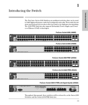
... Gigabit port Power Fault ProCurve Switch 2600-PWR J8762A PoE Status RPS Act EPS LED Mode FDx Fan Spd * Test PoE Reset Clear *Spd mode: off = 10 Mbps, flash = 100 Mbps, on = 1000 Mbps Console ProCurve Switch 2600-8-PWR with Gigabit Uplink (J8762A) PoE-Integrated 10/100-TX Ports (1 - 8) — (Ports are HP Auto-MDIX) Link 1 Mode 2 3 4 Link 5 Mode 6 7 8 Dual-Personality Port: 10/100/1000-T (T) or Mini-GBIC (M) (Port 9T is IEEE Auto MDI/MDIX) Link 9T Mode 9M Link Mode ! Use only one (T or M) for high-speed networking...
... Gigabit port Power Fault ProCurve Switch 2600-PWR J8762A PoE Status RPS Act EPS LED Mode FDx Fan Spd * Test PoE Reset Clear *Spd mode: off = 10 Mbps, flash = 100 Mbps, on = 1000 Mbps Console ProCurve Switch 2600-8-PWR with Gigabit Uplink (J8762A) PoE-Integrated 10/100-TX Ports (1 - 8) — (Ports are HP Auto-MDIX) Link 1 Mode 2 3 4 Link 5 Mode 6 7 8 Dual-Personality Port: 10/100/1000-T (T) or Mini-GBIC (M) (Port 9T is IEEE Auto MDI/MDIX) Link 9T Mode 9M Link Mode ! Use only one (T or M) for high-speed networking...
User Manual
Page 12
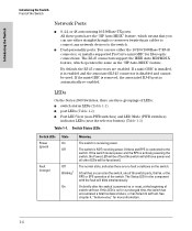
... as the "HP Auto-MDIX" feature. If a mini-GBIC is installed, it is enabled and the associated RJ-45 connector is on the switch, one of the switch ports, the fan, or the RPS or EPS operation of LEDs: ■ switch status LEDs (Table 1-1) ■ port LEDs (Table 1-2) ■ Port LED View (non-PWR switches) and LED Mode (PWR switches) indicator LEDs (near the selector button) (Table 1-3) Table 1-1. LEDs On the Series 2600 Switches, there are three groupings of the switch. Switch Status LEDs Switch LEDs Power (green) Fault...
... as the "HP Auto-MDIX" feature. If a mini-GBIC is installed, it is enabled and the associated RJ-45 connector is on the switch, one of the switch ports, the fan, or the RPS or EPS operation of LEDs: ■ switch status LEDs (Table 1-1) ■ port LEDs (Table 1-2) ■ Port LED View (non-PWR switches) and LED Mode (PWR switches) indicator LEDs (near the selector button) (Table 1-3) Table 1-1. LEDs On the Series 2600 Switches, there are three groupings of the switch. Switch Status LEDs Switch LEDs Power (green) Fault...

User Manual
Page 14
... the fiber-optic ports) from the connected device. Table 1-2. See "Port LED View Select Button and Indicator LEDs" on the next page for more information. Port LEDs Switch LEDs State Meaning Switch 2626 and Switch 2650 Port LEDs (green - The switch Fault, and Self Test LEDs will blink with the port number) Displays port link information, network activity information, whether the port is configured for full-duplex operation, or the speed of these condition exists: • no active network cable is connected to indicate a status change. 1-6 Series...
... the fiber-optic ports) from the connected device. Table 1-2. See "Port LED View Select Button and Indicator LEDs" on the next page for more information. Port LEDs Switch LEDs State Meaning Switch 2626 and Switch 2650 Port LEDs (green - The switch Fault, and Self Test LEDs will blink with the port number) Displays port link information, network activity information, whether the port is configured for full-duplex operation, or the speed of these condition exists: • no active network cable is connected to indicate a status change. 1-6 Series...
User Manual
Page 17
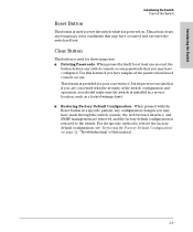
... switch console, the web browser interface, and SNMP management are concerned with the Reset button in a secure location, such as a locked wiring closet. ■ Restoring Factory Default Configuration - For the specific method to the switch. When pressed with the security of the switch configuration and operation, you may have misplaced the password and need console access. This action clears any temporary error conditions that if you are removed, and the factory default configuration is installed in a specific pattern, any switch console access passwords...
... switch console, the web browser interface, and SNMP management are concerned with the Reset button in a secure location, such as a locked wiring closet. ■ Restoring Factory Default Configuration - For the specific method to the switch. When pressed with the security of the switch configuration and operation, you may have misplaced the password and need console access. This action clears any temporary error conditions that if you are removed, and the factory default configuration is installed in a specific pattern, any switch console access passwords...
User Manual
Page 19
... ports with HP Auto-MDIX. ■ dual-personality ports-either 50 or 60 Hz. Cross-over Ethernet (PoE) operation-the 2600-PWR Series switches are IEEE 802.3af compliant and provide up to 15.4W per port to power IP phones, wireless access points, web cameras, and more information, see the POE Planning and Implementation Guide, which is on the Documentation CD-ROM that all ports are enabled-just connect the network cables...
... ports with HP Auto-MDIX. ■ dual-personality ports-either 50 or 60 Hz. Cross-over Ethernet (PoE) operation-the 2600-PWR Series switches are IEEE 802.3af compliant and provide up to 15.4W per port to power IP phones, wireless access points, web cameras, and more information, see the POE Planning and Implementation Guide, which is on the Documentation CD-ROM that all ports are enabled-just connect the network cables...

User Manual
Page 27
... and gently insert it for each Gigabit port 2-7 The ProCurve mini-GBICs are not supported, and their use . Half duplex operation is not supported. ■ Ensure the network cable is disabled and cannot be used. ■ The mini-GBIC ports operate only at full duplex. If a mini-GBIC is installed in product malfunction. Installing the mini-GBICs: Remove the protective plastic cover and retain...
... and gently insert it for each Gigabit port 2-7 The ProCurve mini-GBICs are not supported, and their use . Half duplex operation is not supported. ■ Ensure the network cable is disabled and cannot be used. ■ The mini-GBIC ports operate only at full duplex. If a mini-GBIC is installed in product malfunction. Installing the mini-GBICs: Remove the protective plastic cover and retain...
User Manual
Page 40
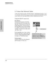
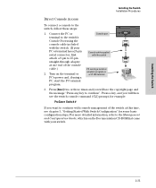
... Link LED does not go on when the network cable is connected to the port, see "Diagnosing With the LEDs" in the switch. When power is at the other end of the port. Using the RJ-45 Connectors To connect: Push the RJ-45 plug into place. hp procurve switch 2650 J4899A 12 1 Self Test Port Lnk Fan Status LED View Act FDx Spd 34 56 eset Clear Spd mode: off = 10 Mbps, flash...
... Link LED does not go on when the network cable is connected to the port, see "Diagnosing With the LEDs" in the switch. When power is at the other end of the port. Using the RJ-45 Connectors To connect: Push the RJ-45 plug into place. hp procurve switch 2650 J4899A 12 1 Self Test Port Lnk Fan Status LED View Act FDx Spd 34 56 eset Clear Spd mode: off = 10 Mbps, flash...

User Manual
Page 41
... internal PoE power supply should go on when the network cable is connected to the port, see the PoE Planning and Implementation Guide and the ProCurve 600/610 External Power Supplies Installation and Getting Started Guide, which is not already providing power to a higher priority switch. For mini-GBICs ports, and in the switch, the type of network connections you will be supplied from an active network device is connected to the port, the port LED for all the switch ports, when a network cable...
... internal PoE power supply should go on when the network cable is connected to the port, see the PoE Planning and Implementation Guide and the ProCurve 600/610 External Power Supplies Installation and Getting Started Guide, which is not already providing power to a higher priority switch. For mini-GBICs ports, and in the switch, the type of network connections you will be supplied from an active network device is connected to the port, the port LED for all the switch ports, when a network cable...

User Manual
Page 50
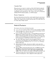
... Series 2600 Switches can be used as a console, directly to operate the console using Telnet from the console, web browser interface, and network management stations The console can simultaneously support one to operate with these methods: ■ Out-of -band console session through the Console Port and in troubleshooting ■ download new software to the switch ■ add passwords to control access to the switch from a PC or UNIX station on the Documentation CD-ROM that you change...
... Series 2600 Switches can be used as a console, directly to operate the console using Telnet from the console, web browser interface, and network management stations The console can simultaneously support one to operate with these methods: ■ Out-of -band console session through the Console Port and in troubleshooting ■ download new software to the switch ■ add passwords to control access to the switch from a PC or UNIX station on the Documentation CD-ROM that you change...
User Manual
Page 51
..., first Console cable supplied with the switch. (If your switch. 2-31 Connect the PC or Console port terminal to the switch's Console Port using a PC, start the PC terminal program. 3. Press [Enter] two or three times and you will see the copyright page and the message "Press any key to 25-pin straight-through adapter at this time, see chapter 3, "Getting Started With Switch Configuration" for example: ProCurve Switch # If you will then see the switch console command (CLI...
..., first Console cable supplied with the switch. (If your switch. 2-31 Connect the PC or Console port terminal to the switch's Console Port using a PC, start the PC terminal program. 3. Press [Enter] two or three times and you will see the copyright page and the message "Press any key to 25-pin straight-through adapter at this time, see chapter 3, "Getting Started With Switch Configuration" for example: ProCurve Switch # If you will then see the switch console command (CLI...
User Manual
Page 61
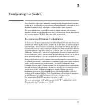
... console Switch Setup screen to quickly assign an IP (Internet Protocol) address and subnet mask to "IP Configuration" in the Management and Configuration Guide, which is on the Documentation CD-ROM that came with your switch. For more information on IP addressing, refer to the switch, set a Manager password, and, optionally, configure other features can be configured through the switch's web browser interface, and from the console and web browser interface. 3 Configuring the Switch This chapter is a guide for using the switch console...
... console Switch Setup screen to quickly assign an IP (Internet Protocol) address and subnet mask to "IP Configuration" in the Management and Configuration Guide, which is on the Documentation CD-ROM that came with your switch. For more information on IP addressing, refer to the switch, set a Manager password, and, optionally, configure other features can be configured through the switch's web browser interface, and from the console and web browser interface. 3 Configuring the Switch This chapter is a guide for using the switch console...

User Manual
Page 63
...], then [S] (for console access. For more information on IP addressing, see the Management and Configuration Guide, which is on your network. Time Zone 0 (none) Optional; 1440 to acquire a time signal. Configuring the Switch 3-3 Here is the menu interface. The number of the next-hop gateway node if network traffic needs to be used in your network to configure IP addressing. The method the switch uses to 48 characters, including spaces Manager Password blank Recommended...
...], then [S] (for console access. For more information on IP addressing, see the Management and Configuration Guide, which is on your network. Time Zone 0 (none) Optional; 1440 to acquire a time signal. Configuring the Switch 3-3 Here is the menu interface. The number of the next-hop gateway node if network traffic needs to be used in your network to configure IP addressing. The method the switch uses to 48 characters, including spaces Manager Password blank Recommended...

User Manual
Page 71
... network port Try power cycling the switch. software failure during self test. 2. You can view the console log at 9600 baud. The mini-GBICs are also tested when they are snug. source, or the switch's power supply may have failed. Call your HP-authorized LAN dealer, or use the electronic support services from is still not on, verify the AC power source works by pressing the Reset button on the next page Troubleshooting 4-5 Troubleshooting Diagnosing...
... network port Try power cycling the switch. software failure during self test. 2. You can view the console log at 9600 baud. The mini-GBICs are also tested when they are snug. source, or the switch's power supply may have failed. Call your HP-authorized LAN dealer, or use the electronic support services from is still not on, verify the AC power source works by pressing the Reset button on the next page Troubleshooting 4-5 Troubleshooting Diagnosing...
User Manual
Page 72
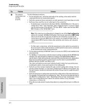
... patch panels in the associated slot. • For 1000Base-T connections, verify the network cabling complies with the LEDs Tip Problem Solution ➏ The network Try the following procedures: connection is changed to the fixed 10/100 or 10/100/1000 ports, if the port is configured as "Auto", the port on hubs, other switches, and routers, use the console interface, or, if you have configured an IP address on the port type, twisted...
... patch panels in the associated slot. • For 1000Base-T connections, verify the network cabling complies with the LEDs Tip Problem Solution ➏ The network Try the following procedures: connection is changed to the fixed 10/100 or 10/100/1000 ports, if the port is configured as "Auto", the port on hubs, other switches, and routers, use the console interface, or, if you have configured an IP address on the port type, twisted...
User Manual
Page 77
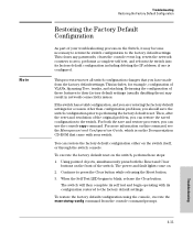
... you are restoring the factory default settings for example, configuration of the original problem, you can restore the factory default configuration either on the switch, perform these features to their factory default settings (usually disabling them) may become necessary to return the switch configuration to the factory default settings. For both the Reset and Clear buttons on . 2. The power and fault lights come on the front of the switch. This clears any passwords, clears the console event log, resets the network counters to the factory default settings.
... you are restoring the factory default settings for example, configuration of the original problem, you can restore the factory default configuration either on the switch, perform these features to their factory default settings (usually disabling them) may become necessary to return the switch configuration to the factory default settings. For both the Reset and Clear buttons on . 2. The power and fault lights come on the front of the switch. This clears any passwords, clears the console event log, resets the network counters to the factory default settings.

User Manual
Page 78
... on the Documentation CDROM that they offer and with your switch. The ProCurve Web site, http://www.procurve.com also provides upto-date support information. Additionally, your HP-authorized network reseller can be available on how to use of a number of your network topology map, including your network records network addresses assigned to the relevant devices Troubleshooting 4-12 For more information, see the Management and Configuration Guide, which is...
... on the Documentation CDROM that they offer and with your switch. The ProCurve Web site, http://www.procurve.com also provides upto-date support information. Additionally, your HP-authorized network reseller can be available on how to use of a number of your network topology map, including your network records network addresses assigned to the relevant devices Troubleshooting 4-12 For more information, see the Management and Configuration Guide, which is...
User Manual
Page 109
...1-10 power connector ... 1-11 backbone switch topology with ... 2-35, 2-38-2-39 basic switch configuration IP address ... 3-3 manager password ... 3-2 subnet mask ... 3-3 Switch Setup screen ... 3-2 basic troubleshooting tips ... 4-1 blinking LEDs error indications ... 4-4 Bootp automatic switch configuration ... 3-2 for direct console connection ... 2-31 Index - 1 Index A-3 cables 1000Base-LH connections ... 2-6 fiber-optic cable specifications ... B-7, B-9 HP Auto-MDIX feature ... A-2 auto MDI/MDI-X operation ... B-2 1000Base-SX connections ... 2-6 fiber-optic cable specifications...
...1-10 power connector ... 1-11 backbone switch topology with ... 2-35, 2-38-2-39 basic switch configuration IP address ... 3-3 manager password ... 3-2 subnet mask ... 3-3 Switch Setup screen ... 3-2 basic troubleshooting tips ... 4-1 blinking LEDs error indications ... 4-4 Bootp automatic switch configuration ... 3-2 for direct console connection ... 2-31 Index - 1 Index A-3 cables 1000Base-LH connections ... 2-6 fiber-optic cable specifications ... B-7, B-9 HP Auto-MDIX feature ... A-2 auto MDI/MDI-X operation ... B-2 1000Base-SX connections ... 2-6 fiber-optic cable specifications...
User Manual
Page 111
...front of switch ... 1-3 10/100Base-TX ports ... 1-3 Clear button ... 1-9 description ... 1-3 dual-personality ports ... 1-4 LEDs ... 1-4 network ports ... 1-4 Reset button ... 1-9 full-duplex fixed configuration effects on network connections ... 4-1 full-duplex operation of mini-GBICs ... 2-7 G Gigabit-LH ports, cables used with ... B-2 Gigabit-SX ports, cables used with ... B-2 H horizontal surface mounting switch on switch ... 1-3 showing error conditions ... 4-4 features console ... 2-30 switch ... 1-11 fiber-optic cables ... B-5 I in-band ... 3-1 in-band console access types of...
...front of switch ... 1-3 10/100Base-TX ports ... 1-3 Clear button ... 1-9 description ... 1-3 dual-personality ports ... 1-4 LEDs ... 1-4 network ports ... 1-4 Reset button ... 1-9 full-duplex fixed configuration effects on network connections ... 4-1 full-duplex operation of mini-GBICs ... 2-7 G Gigabit-LH ports, cables used with ... B-2 Gigabit-SX ports, cables used with ... B-2 H horizontal surface mounting switch on switch ... 1-3 showing error conditions ... 4-4 features console ... 2-30 switch ... 1-11 fiber-optic cables ... B-5 I in-band ... 3-1 in-band console access types of...

User Manual
Page 113
...Power LED behavior ... 2-11 Self Test LED ... 1-5 behavior during factory default reset ... 4-11 behavior during self test ... 2-10 serial cable for direct console connection ... 2-31 SFP ports ... 1-2 slots for troubleshooting ... 4-1 topologies effects of improper topology ... 4-2 samples of Reset button ... 1-9 troubleshooting procedure ... 4-9 RPS/EPS ... 2-21 cables ... 2-22 connecting to a switch ... 2-24-2-26 operation ... 2-22 S safety and regulatory statements ... A-2 features ... 1-11 front panel description ... 1-3 included parts ... 2-1 LED descriptions ... 1-4 mounting in a rack...
...Power LED behavior ... 2-11 Self Test LED ... 1-5 behavior during factory default reset ... 4-11 behavior during self test ... 2-10 serial cable for direct console connection ... 2-31 SFP ports ... 1-2 slots for troubleshooting ... 4-1 topologies effects of improper topology ... 4-2 samples of Reset button ... 1-9 troubleshooting procedure ... 4-9 RPS/EPS ... 2-21 cables ... 2-22 connecting to a switch ... 2-24-2-26 operation ... 2-22 S safety and regulatory statements ... A-2 features ... 1-11 front panel description ... 1-3 included parts ... 2-1 LED descriptions ... 1-4 mounting in a rack...


