User Manual
Page 6
...Address for Remote Switch Management 3-5 Starting a Telnet Session 3-5 Starting a Web Browser Session 3-5 4 Troubleshooting Basic Troubleshooting Tips 4-1 Diagnosing with the LEDs 4-4 Proactive Networking 4-8 Hardware Diagnostic Tests 4-9 Testing the Switch by Resetting It 4-9 Checking the Switch LEDs 4-9 Checking Console Messages 4-9 Testing Twisted-Pair Cabling 4-10 Testing Switch-to-Device Network Communications 4-10 Testing End-to-End Network Communications 4-10 Restoring the Factory Default Configuration 4-11 Downloading New Switch Software 4-12 HP Customer Support Services...
...Address for Remote Switch Management 3-5 Starting a Telnet Session 3-5 Starting a Web Browser Session 3-5 4 Troubleshooting Basic Troubleshooting Tips 4-1 Diagnosing with the LEDs 4-4 Proactive Networking 4-8 Hardware Diagnostic Tests 4-9 Testing the Switch by Resetting It 4-9 Checking the Switch LEDs 4-9 Checking Console Messages 4-9 Testing Twisted-Pair Cabling 4-10 Testing Switch-to-Device Network Communications 4-10 Testing End-to-End Network Communications 4-10 Restoring the Factory Default Configuration 4-11 Downloading New Switch Software 4-12 HP Customer Support Services...
User Manual
Page 7
A Specifications Physical A-1 Electrical A-1 Environmental A-1 Acoustic A-2 Connectors A-2 Safety A-2 Lasers A-2 B Switch Ports and Network Cables Switch Ports B-1 Twisted-Pair Cables B-1 Mode Conditioning Patch Cord for Gigabit-LX B-3 Installing the Patch Cord B-4 Recommended Patch Cords B-4 Twisted-Pair Cable/Connector Pin-Outs B-5 Straight-Through Twisted-Pair Cable for 10 Mbps or 100 Mbps Network Connections B-7 Cable Diagram B-7 Pin Assignments B-7 Crossover Twisted-Pair Cable for 10 Mbps or 100 Mbps Network Connection B-8 Cable Diagram B-8 Pin Assignments B-8 Straight-...
A Specifications Physical A-1 Electrical A-1 Environmental A-1 Acoustic A-2 Connectors A-2 Safety A-2 Lasers A-2 B Switch Ports and Network Cables Switch Ports B-1 Twisted-Pair Cables B-1 Mode Conditioning Patch Cord for Gigabit-LX B-3 Installing the Patch Cord B-4 Recommended Patch Cords B-4 Twisted-Pair Cable/Connector Pin-Outs B-5 Straight-Through Twisted-Pair Cable for 10 Mbps or 100 Mbps Network Connections B-7 Cable Diagram B-7 Pin Assignments B-7 Crossover Twisted-Pair Cable for 10 Mbps or 100 Mbps Network Connection B-8 Cable Diagram B-8 Pin Assignments B-8 Straight-...
User Manual
Page 10
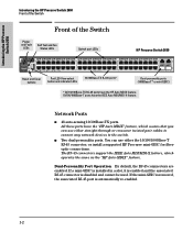
... is automatically re-enabled. 1-2 All these ports have the IEEE Auto MDI/MDI-X feature. Introducing the HP Procurve Switch 2650 Introducing the HP Procurve Switch 2650 Front of the Switch Front of the Switch Power and Fault LEDs Self Test and Fan Status LEDs Switch port LEDs HP Procurve Switch 2650 Power Fault hp procurve switch 2650 J4899A 12 1 Self Test Port Lnk LED View Act Fan Status FDx Spd 34 56 78 9 10 11 12 Reset Clear Spd mode: off = 10 Mbps, flash = 100 Mbps, on...
... is automatically re-enabled. 1-2 All these ports have the IEEE Auto MDI/MDI-X feature. Introducing the HP Procurve Switch 2650 Introducing the HP Procurve Switch 2650 Front of the Switch Front of the Switch Power and Fault LEDs Self Test and Fan Status LEDs Switch port LEDs HP Procurve Switch 2650 Power Fault hp procurve switch 2650 J4899A 12 1 Self Test Port Lnk LED View Act Fan Status FDx Spd 34 56 78 9 10 11 12 Reset Clear Spd mode: off = 10 Mbps, flash = 100 Mbps, on...
User Manual
Page 11
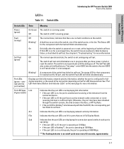
... have been disabled through the switch console, the web browser interface, or HP TopTools. • if the port LED is not receiving link beat or sufficient light. On On briefly after you "hot swap" a mini-GBIC into the switch; Act Indicates that the port LEDs are no active network cable connected, or is blinking* simultaneously with the fault will blink simultaneously. The switch is receiving power. The switch self test and initialization...
... have been disabled through the switch console, the web browser interface, or HP TopTools. • if the port LED is not receiving link beat or sufficient light. On On briefly after you "hot swap" a mini-GBIC into the switch; Act Indicates that the port LEDs are no active network cable connected, or is blinking* simultaneously with the fault will blink simultaneously. The switch is receiving power. The switch self test and initialization...
User Manual
Page 12
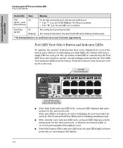
... in Link mode and it flickers as network traffic is received and transmitted through the port. ■ If the Full Duplex (FDx) indicator LED is lit, each port) Power Fault hp procurve switch 2650 J4899A 12 1 Self Test Port Lnk LED View Act Fan Status FDx Spd 34 56 78 9 10 Reset Clear Spd mode: off = 10 Mbps, flash = 100 Mbps, on /off cycle once every 1.6 seconds, approximately. Port LED View Select Button and Indicator LEDs...
... in Link mode and it flickers as network traffic is received and transmitted through the port. ■ If the Full Duplex (FDx) indicator LED is lit, each port) Power Fault hp procurve switch 2650 J4899A 12 1 Self Test Port Lnk LED View Act Fan Status FDx Spd 34 56 78 9 10 Reset Clear Spd mode: off = 10 Mbps, flash = 100 Mbps, on /off cycle once every 1.6 seconds, approximately. Port LED View Select Button and Indicator LEDs...

User Manual
Page 13
... through the switch console, the web browser interface, and SNMP management are concerned with the Reset button in chapter 4, "Troubleshooting" of this feature if you may have configured. When pressed with the security of the Switch ■ If the Speed (Spd) indicator LED is lit, the port LEDs behave as a locked wiring closet. ■ Restoring Factory Default Configuration - This button is provided for at least one second, the button deletes any switch console access passwords that...
... through the switch console, the web browser interface, and SNMP management are concerned with the Reset button in chapter 4, "Troubleshooting" of this feature if you may have configured. When pressed with the security of the Switch ■ If the Speed (Spd) indicator LED is lit, the port LEDs behave as a locked wiring closet. ■ Restoring Factory Default Configuration - This button is provided for at least one second, the button deletes any switch console access passwords that...
User Manual
Page 32
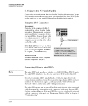
... Test Port Lnk LED View Act Fan Status FDx Spd 34 56 eset Clear Spd mode: off = 10 Mbps, flash = RJ-45 connector Unshielded twisted-pair cable: • Category 3, 4, or 5 for 10 Mbps ports • Category 5 or better for 100 Mbps ports • Category 5E or better for the mini-GBIC cabling information. When power is on for the switch and for the connected device, the Link LED for...
... Test Port Lnk LED View Act Fan Status FDx Spd 34 56 eset Clear Spd mode: off = 10 Mbps, flash = RJ-45 connector Unshielded twisted-pair cable: • Category 3, 4, or 5 for 10 Mbps ports • Category 5 or better for 100 Mbps ports • Category 5E or better for the mini-GBIC cabling information. When power is on for the switch and for the connected device, the Link LED for...
User Manual
Page 33
... configure the switch with a serial cable for connecting a PC or VT-100 terminal, to be accessed through the Console Port and one to help in -band Telnet console session. The Switch 2650 can be used as a console, directly to the switch. ■ In-Band: Access the console using either one in troubleshooting ■ Download new software to the switch ■ Add passwords to control access to the switch from the console, web browser interface, and network management stations The console can simultaneously support...
... configure the switch with a serial cable for connecting a PC or VT-100 terminal, to be accessed through the Console Port and one to help in -band Telnet console session. The Switch 2650 can be used as a console, directly to the switch. ■ In-Band: Access the console using either one in troubleshooting ■ Download new software to the switch ■ Add passwords to control access to the switch from the console, web browser interface, and network management stations The console can simultaneously support...
User Manual
Page 34
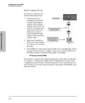
... a 25-pin serial connector, Console cable supplied with console management of the console cable.) 2. Installing the Switch 2650 Installing the Switch 2650 Installation Procedures Direct Console Access To connect a console to the Management and Configuration Guide, which is on the terminal or PC running a terminal emulator program, or a VT-100 terminal PC's power and, if using the console cable included with the Switch 2650. (If your switch. 2-18 Connect the PC or Console port terminal to continue". Press a key, and you...
... a 25-pin serial connector, Console cable supplied with console management of the console cable.) 2. Installing the Switch 2650 Installing the Switch 2650 Installation Procedures Direct Console Access To connect a console to the Management and Configuration Guide, which is on the terminal or PC running a terminal emulator program, or a VT-100 terminal PC's power and, if using the console cable included with the Switch 2650. (If your switch. 2-18 Connect the PC or Console port terminal to continue". Press a key, and you...
User Manual
Page 39
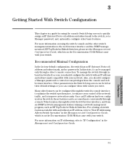
... accessed more information on using the console Switch Setup screen to quickly assign an IP (Internet Protocol) address and subnet mask to enhance your switch. 3 Getting Started With Switch Configuration This chapter is on the Documentation CD-ROM that came with your switch. Other parameters in the Management and Configuration Guide, which is a guide for using the switch console and the other switch management interfaces: the web browser interface and the SNMP management tool, HP TopTools for Hubs & Switches. For a listing of the network traffic...
... accessed more information on using the console Switch Setup screen to quickly assign an IP (Internet Protocol) address and subnet mask to enhance your switch. 3 Getting Started With Switch Configuration This chapter is on the Documentation CD-ROM that came with your switch. Other parameters in the Management and Configuration Guide, which is a guide for using the switch console and the other switch management interfaces: the web browser interface and the SNMP management tool, HP TopTools for Hubs & Switches. For a listing of the network traffic...
User Manual
Page 40
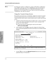
... with your network is on the Documentation CD-ROM that came with the default settings. Getting Started With Switch Configuration 3. At the prompt, enter the setup command to acquire an IP address configuration from a DHCP or Bootp server. To use DHCP/Bootp instead of up to 16 characters. 3-2 The CLI prompt appears displaying the switch model number: HP Procurve Switch 2650# 2. Use the [Tab] key to select the Manager Password field and enter a manager password of the manual method described...
... with your network is on the Documentation CD-ROM that came with the default settings. Getting Started With Switch Configuration 3. At the prompt, enter the setup command to acquire an IP address configuration from a DHCP or Bootp server. To use DHCP/Bootp instead of up to 16 characters. 3-2 The CLI prompt appears displaying the switch model number: HP Procurve Switch 2650# 2. Use the [Tab] key to select the Manager Password field and enter a manager password of the manual method described...
User Manual
Page 41
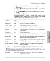
... the command line interface for Save). The number of the next-hop gateway node if network traffic needs to be able to 48 characters, including spaces Manager Password blank Recommended; Time Sync Method None Optional; The alternative is on your network or the switch will be used in the Setup screen. Community Name public Default setting recommended. TimeP Mode Disabled Optional; IP Address xxx.xxx.xxx.xxx Recommended; Getting Started With Switch Configuration...
... the command line interface for Save). The number of the next-hop gateway node if network traffic needs to be able to 48 characters, including spaces Manager Password blank Recommended; Time Sync Method None Optional; The alternative is on your network or the switch will be used in the Setup screen. Community Name public Default setting recommended. TimeP Mode Disabled Optional; IP Address xxx.xxx.xxx.xxx Recommended; Getting Started With Switch Configuration...

User Manual
Page 43
... connect to the switch's IP address). 2. Getting Started With Switch Configuration Using the IP Address for Remote Switch Management Using the IP Address for Remote Switch Management With your web browser and typing in the switch's IP address as the URL. You will then see the copyright page and the message "Press any PC or workstation on the network by running the Telnet session (for example: HP Procurve Switch 2650# Enter help information about the command. Starting a Telnet Session To access...
... connect to the switch's IP address). 2. Getting Started With Switch Configuration Using the IP Address for Remote Switch Management Using the IP Address for Remote Switch Management With your web browser and typing in the switch's IP address as the URL. You will then see the copyright page and the message "Press any PC or workstation on the network by running the Telnet session (for example: HP Procurve Switch 2650# Enter help information about the command. Starting a Telnet Session To access...

User Manual
Page 46
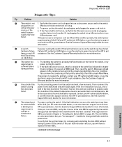
... that will default to provide some topology configuration guidelines can seriously impair network performance. Troubleshooting Basic Troubleshooting Tips • If the connected device has a fixed configuration, for example 100 Mbps, at half or full duplex, the switch will automatically sense the link speed, but will severely impact your network performance. The result will not connect correctly to be enabled through the switch console, the web browser interface, or HP TopTools...
... that will default to provide some topology configuration guidelines can seriously impair network performance. Troubleshooting Basic Troubleshooting Tips • If the connected device has a fixed configuration, for example 100 Mbps, at half or full duplex, the switch will automatically sense the link speed, but will severely impact your network performance. The result will not connect correctly to be enabled through the switch console, the web browser interface, or HP TopTools...

User Manual
Page 47
..., refer to determine the port's configuration and verify that there is on the Documentation CD-ROM that may not be used for a single network connection without causing a data path loop. Troubleshooting Basic Troubleshooting Tips The Switch 2650 also supports Trunking, which allows multiple network cables to be operating as disabled through software. A port on your switch. For more information on the HP Procurve web site, http://www.hp.com/go/hpprocurve, in a blocking state...
..., refer to determine the port's configuration and verify that there is on the Documentation CD-ROM that may not be used for a single network connection without causing a data path loop. Troubleshooting Basic Troubleshooting Tips The Switch 2650 also supports Trunking, which allows multiple network cables to be operating as disabled through software. A port on your switch. For more information on the HP Procurve web site, http://www.hp.com/go/hpprocurve, in a blocking state...
User Manual
Page 49
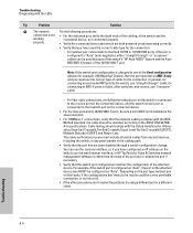
... your HP-authorized LAN dealer, or use the electronic support services from HP to get assistance. experienced a self test or initialization failure. the LEDs will be replaced. If the error indication reoccurs, one of the fans has failed. If the port is a mini-GBIC, verify that point by unplugging and plugging the power cord back in Chapter 2, "Installing the Switch 2650" on the console screen and in chapter 2) and configure...
... your HP-authorized LAN dealer, or use the electronic support services from HP to get assistance. experienced a self test or initialization failure. the LEDs will be replaced. If the error indication reoccurs, one of the fans has failed. If the port is a mini-GBIC, verify that point by unplugging and plugging the power cord back in Chapter 2, "Installing the Switch 2650" on the console screen and in chapter 2) and configure...
User Manual
Page 50
...-568A-5 specifications. Note: If the switch port configuration is configured to the transmit port on the port type, twisted-pair or fiber-optic, if the configurations don't match, the results could be a very unreliable connection, or no link at the switch and the working connected device, are both ends of the attached device. for the connection: - Cable testing should be configured as MDI-X only and you have used because of the switch's "HP Auto-MDIX...
...-568A-5 specifications. Note: If the switch port configuration is configured to the transmit port on the port type, twisted-pair or fiber-optic, if the configurations don't match, the results could be a very unreliable connection, or no link at the switch and the working connected device, are both ends of the attached device. for the connection: - Cable testing should be configured as MDI-X only and you have used because of the switch's "HP Auto-MDIX...
User Manual
Page 55
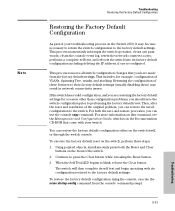
... console command prompt. 4-11 Troubleshooting For both the Reset and Clear buttons on the Documentation CD-ROM that you can use the console copy command. Using pointed objects, simultaneously press both the save the switch configuration prior to zero, performs a complete self test, and reboots the switch into its factory default configuration including deleting the IP address, if one is on the front of the switch. 2. When the Self Test LED begins to the factory default settings...
... console command prompt. 4-11 Troubleshooting For both the Reset and Clear buttons on the Documentation CD-ROM that you can use the console copy command. Using pointed objects, simultaneously press both the save the switch configuration prior to zero, performs a complete self test, and reboots the switch into its factory default configuration including deleting the IP address, if one is on the front of the switch. 2. When the Self Test LED begins to the factory default settings...
User Manual
Page 80
...18 configuration checking when troubleshooting ... 4-3 DHCP/Bootp ... 3-2 full duplex only for mini-GBICs ... 2-6 IP address ... 3-3 IP address, manually ... 3-2 manager password ... 3-2 restoring factory defaults ... 1-5, 4-11 subnet mask ... 3-3 Switch Setup screen ... 3-2 connecting the switch to connect out-of-band ... 2-17 serial cable connection ... 2-18 Switch Setup screen ... 3-2 Telnet access ... 3-5 terminal configuration ... 2-17 console port location on switch ... 1-2 showing error conditions ... 4-4 FDx LED ... 1-3-1-4 features console ... 2-17 switch ... 1-7 fiber-optic cables...
...18 configuration checking when troubleshooting ... 4-3 DHCP/Bootp ... 3-2 full duplex only for mini-GBICs ... 2-6 IP address ... 3-3 IP address, manually ... 3-2 manager password ... 3-2 restoring factory defaults ... 1-5, 4-11 subnet mask ... 3-3 Switch Setup screen ... 3-2 connecting the switch to connect out-of-band ... 2-17 serial cable connection ... 2-18 Switch Setup screen ... 3-2 Telnet access ... 3-5 terminal configuration ... 2-17 console port location on switch ... 1-2 showing error conditions ... 4-4 FDx LED ... 1-3-1-4 features console ... 2-17 switch ... 1-7 fiber-optic cables...
User Manual
Page 82
... devices connecting to the switch ... 2-16 network ports connecting to ... 2-15 precautions mounting the switch ... 2-3 power requirements ... 2-3 preparing the installation site ... 2-4 Proactive Network tools diagnostics with the Clear button ... 3-4 if you lose the password ... 3-4 passwords, deleting ... 1-5 physical specifications, switch ... A-1 Ping test ... 4-10 pin-outs twisted-pair cables ... B-5 required types ... 2-4 twisted-pair connector pin-outs ... A-2 types of ... 1-2, 2-4 non-standard network cables, effects ... 4-2 O out-of Reset button ... 1-5 troubleshooting...
... devices connecting to the switch ... 2-16 network ports connecting to ... 2-15 precautions mounting the switch ... 2-3 power requirements ... 2-3 preparing the installation site ... 2-4 Proactive Network tools diagnostics with the Clear button ... 3-4 if you lose the password ... 3-4 passwords, deleting ... 1-5 physical specifications, switch ... A-1 Ping test ... 4-10 pin-outs twisted-pair cables ... B-5 required types ... 2-4 twisted-pair connector pin-outs ... A-2 types of ... 1-2, 2-4 non-standard network cables, effects ... 4-2 O out-of Reset button ... 1-5 troubleshooting...


