
User Manual
Page 4
... be construed as constituting an additional warranty. HP shall not be liable for errors contained herein or for the use of this material. Publication Number 5991-8597 December 2007 Applicable Products ProCurve Switch 5308xl (J4819A) ProCurve Switch 5372xl (J4848B) ProCurve Switch 5348xl... PURPOSE. Warranty See the Customer Support/Warranty booklet included with the furnishing, performance, or use or reliability of the specific warranty terms applicable to change without notice. The information contained herein is not furnished by Hewlett-Packard. Hewlett-Packard assumes...
... be construed as constituting an additional warranty. HP shall not be liable for errors contained herein or for the use of this material. Publication Number 5991-8597 December 2007 Applicable Products ProCurve Switch 5308xl (J4819A) ProCurve Switch 5372xl (J4848B) ProCurve Switch 5348xl... PURPOSE. Warranty See the Customer Support/Warranty booklet included with the furnishing, performance, or use or reliability of the specific warranty terms applicable to change without notice. The information contained herein is not furnished by Hewlett-Packard. Hewlett-Packard assumes...
User Manual
Page 7
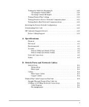
...-Device Network Communications 4-11 Testing End-to-End Network Communications 4-11 Restoring the Factory Default Configuration 4-12 Downloading New Code 4-13 HP Customer Support Services 4-13 Before Calling Support 4-13 A Specifications Physical A-1 Electrical A-1 Environmental A-1 Acoustic A-2 Switch 5308xl and Switch 5372xl A-2 Switch 5304xl and Switch 5348xl A-2 Network Connectors A-2 Safety A-2 B Switch Ports and Network...
...-Device Network Communications 4-11 Testing End-to-End Network Communications 4-11 Restoring the Factory Default Configuration 4-12 Downloading New Code 4-13 HP Customer Support Services 4-13 Before Calling Support 4-13 A Specifications Physical A-1 Electrical A-1 Environmental A-1 Acoustic A-2 Switch 5308xl and Switch 5372xl A-2 Switch 5304xl and Switch 5348xl A-2 Network Connectors A-2 Safety A-2 B Switch Ports and Network...

User Manual
Page 14
... the switch Off module slots) Flashing† A module is installed in Full Duplex Mode. for the fiber-optic ports) from the connected device. Indicates that specific error packets are located on the modules themselves, one pair for each error packet that are displaying network activity information. Switch Module LEDs The following...
... the switch Off module slots) Flashing† A module is installed in Full Duplex Mode. for the fiber-optic ports) from the connected device. Indicates that specific error packets are located on the modules themselves, one pair for each error packet that are displaying network activity information. Switch Module LEDs The following...

User Manual
Page 16
... powered on . Reset Button This button is used to reset the switch while it is installed in a specific pattern, the Clear button clears any temporary error conditions that you may have configured. For the specific method to restore the factory default configuration, see "Restoring the Factory Default Configuration" in the switch console...
... powered on . Reset Button This button is used to reset the switch while it is installed in a specific pattern, the Clear button clears any temporary error conditions that you may have configured. For the specific method to restore the factory default configuration, see "Restoring the Factory Default Configuration" in the switch console...

User Manual
Page 26
... (STP) balanced cable. Note: Gigabit-LH - Prepare the Installation Site Installing the Switch 5300xl Series Cabling Infrastructure Ensure the cabling infrastructure meets the necessary network specifications. See the following table for cable types and lengths, and see appendix B, "Switch Ports and Network Cables" on the particular fiber loss and coupling loss...
... (STP) balanced cable. Note: Gigabit-LH - Prepare the Installation Site Installing the Switch 5300xl Series Cabling Infrastructure Ensure the cabling infrastructure meets the necessary network specifications. See the following table for cable types and lengths, and see appendix B, "Switch Ports and Network Cables" on the particular fiber loss and coupling loss...

User Manual
Page 27
...-2 Type B1 standards. Note: Conditioning patch cord cables are not supported on an engineered fiber optic link that meets standards in the specification). single-mode cable: 2-30 kilometers (40 kilometers, on 10-GbE. 12 fiber 50/125 μm (core/cladding) diameter, multimode... diameter, multimode Fiber ribbon cable is also supported. 50 μm cable or 62.5 μm cable: 100 meters Copper Cables Cable Specifications Length Limit Shielded twitsted-pair cables complying with the 802.3ak standard. 0.5-15 metersCX4 Installation Location Before installing the switch, plan its location...
...-2 Type B1 standards. Note: Conditioning patch cord cables are not supported on an engineered fiber optic link that meets standards in the specification). single-mode cable: 2-30 kilometers (40 kilometers, on 10-GbE. 12 fiber 50/125 μm (core/cladding) diameter, multimode... diameter, multimode Fiber ribbon cable is also supported. 50 μm cable or 62.5 μm cable: 100 meters Copper Cables Cable Specifications Length Limit Shielded twitsted-pair cables complying with the 802.3ak standard. 0.5-15 metersCX4 Installation Location Before installing the switch, plan its location...

User Manual
Page 45
... ports. 2-25 The 10-GbE module supports trunking - Traffic from the trunk. Installing the Switch 5300xl Series Example Network Topologies Used as per the LACP specification, are disabled or disconnected, the highest priority "standby" port(s) will then be added to the trunk and the disabled/disconnected port(s) will be placed in...
... ports. 2-25 The 10-GbE module supports trunking - Traffic from the trunk. Installing the Switch 5300xl Series Example Network Topologies Used as per the LACP specification, are disabled or disconnected, the highest priority "standby" port(s) will then be added to the trunk and the disabled/disconnected port(s) will be placed in...

User Manual
Page 53
... configuration: ■ configuration of the 740wl/760wl ■ configuration of the module ■ configuration of the 5300xl switch 740wl/760wl Configuration HP recommends the use of a static IP address for the IP address mask combination. 3-7 Getting Started With Switch Configuration If the IP address...CIDR notation "/mask bit number" (for example 10.1.1.1/24) is an acceptable shortcut for the 740wl/760wl. If you need to configure a specific IP address for the module, do the following: From the CLI command prompt at the global configuration level ProCurve Switch 5308xl (config) # enter...
... configuration: ■ configuration of the 740wl/760wl ■ configuration of the module ■ configuration of the 5300xl switch 740wl/760wl Configuration HP recommends the use of a static IP address for the IP address mask combination. 3-7 Getting Started With Switch Configuration If the IP address...CIDR notation "/mask bit number" (for example 10.1.1.1/24) is an acceptable shortcut for the 740wl/760wl. If you need to configure a specific IP address for the module, do the following: From the CLI command prompt at the global configuration level ProCurve Switch 5308xl (config) # enter...

User Manual
Page 68
...twisted-pair connections, in the cabling path. • Verify the port has not been disabled through a switch configuration change. See the "HP Auto-MDIX Feature" description on page B-4 for the connection. - for example, 100-Full Duplex), then the port operates as MDI-X only... using a different port or a different cable. The cable should comply with the stated limitations for connecting to the ANSI/TIA/EIA568-A-5 specifications. If the other switches, and routers, use straight-through or a crossover cable can use the web browser interface, or ProCurve Manager...
...twisted-pair connections, in the cabling path. • Verify the port has not been disabled through a switch configuration change. See the "HP Auto-MDIX Feature" description on page B-4 for the connection. - for example, 100-Full Duplex), then the port operates as MDI-X only... using a different port or a different cable. The cable should comply with the stated limitations for connecting to the ANSI/TIA/EIA568-A-5 specifications. If the other switches, and routers, use straight-through or a crossover cable can use the web browser interface, or ProCurve Manager...

User Manual
Page 75
A Specifications Specifications Physical Width: 44.2 cm (17.2 in) Depth: 39.0 cm (15.2 in) Height: • Switch 5308xl, 5372xl, 5308xl-48G • 22.5 cm (8.7 in) • Switch 5304xl, ...
A Specifications Specifications Physical Width: 44.2 cm (17.2 in) Depth: 39.0 cm (15.2 in) Height: • Switch 5308xl, 5372xl, 5308xl-48G • 22.5 cm (8.7 in) • Switch 5304xl, ...

User Manual
Page 76
Safety ■ EN60950 / IEC 950 ■ CSA 22.2 No. 950 (cUL1950) ■ UL 1950 3rd Edition A-2 Specifications Specifications Acoustic Switch 5308xl and Switch 5372xl: Geräuschemission LwA=63.1 dB am fiktiven Arbeitsplatz nach DIN 45635 T.19 Noise Emission LwA=63.1 dB in a ...
Safety ■ EN60950 / IEC 950 ■ CSA 22.2 No. 950 (cUL1950) ■ UL 1950 3rd Edition A-2 Specifications Specifications Acoustic Switch 5308xl and Switch 5372xl: Geräuschemission LwA=63.1 dB am fiktiven Arbeitsplatz nach DIN 45635 T.19 Noise Emission LwA=63.1 dB in a ...

User Manual
Page 77
... 100/1000-T xl Module accept 100-ohm differential unshielded and shielded twisted-pair cable with the Switch 5300xl Series, including minimum pin-out information and specifications for LAN communications. It is the most common cause of problems for twisted-pair cables.
... 100/1000-T xl Module accept 100-ohm differential unshielded and shielded twisted-pair cable with the Switch 5300xl Series, including minimum pin-out information and specifications for LAN communications. It is the most common cause of problems for twisted-pair cables.

User Manual
Page 78
...Requirements", below) Note on your site. When testing your cabling, be sure to carry 1000Base-T networking must comply with the Category 5e specifications, as all four-pairs are frequently overlooked when testing cable and they must pass tests for Equal-Level Far-End Crosstalk (ELFEXT), Multiple ... 3, 4, or 5 100-ohm differential unshielded twistedpair (UTP) or shielded twisted-pair (STP) cable, complying with IEEE 802.3 Type 10Base-T specifications, fitted with RJ-45 connectors. 100 Mbps Operation Category 5 100-ohm differential UTP or STP cable, complying with IEEE 802.3u 100Base-TX...
...Requirements", below) Note on your site. When testing your cabling, be sure to carry 1000Base-T networking must comply with the Category 5e specifications, as all four-pairs are frequently overlooked when testing cable and they must pass tests for Equal-Level Far-End Crosstalk (ELFEXT), Multiple ... 3, 4, or 5 100-ohm differential unshielded twistedpair (UTP) or shielded twisted-pair (STP) cable, complying with IEEE 802.3 Type 10Base-T specifications, fitted with RJ-45 connectors. 100 Mbps Operation Category 5 100-ohm differential UTP or STP cable, complying with IEEE 802.3u 100Base-TX...

User Manual
Page 79
... Ports and Network Cables Switch Ports and Network Cables Fiber-Optic Cables Port Type Gigabit-SX Gigabit-LX Gigabit-LH 100BaseFX 10-GbE SR Cable Specifications Connector Type Maximum Length 62.5/125 mm or 50/125 μm (core/cladding) diameter, graded-index 850 nm, low metal content, multimode fiber-optic cables...
... Ports and Network Cables Switch Ports and Network Cables Fiber-Optic Cables Port Type Gigabit-SX Gigabit-LX Gigabit-LH 100BaseFX 10-GbE SR Cable Specifications Connector Type Maximum Length 62.5/125 mm or 50/125 μm (core/cladding) diameter, graded-index 850 nm, low metal content, multimode fiber-optic cables...

User Manual
Page 80
... the 802.3ak standard) Connector Type CX4 Supported Length 0.5-15 meters Switch Ports and Network Cables Twisted-Pair Cable/Connector Pin-Outs The HP Auto-MDIX Feature. Note: Conditioning patch cord cables are not supported for any connection, a straight-through twisted-pair cable can also be... used -- Switch Ports and Network Cables Twisted-Pair Cable/Connector Pin-Outs Port Type 10-GbE LR 10-GbE ER OMC CX4 Fiber Cable Specifications Connector Type Maximum Length 9/125 μm (core/cladding) diameter, 1310 nm, low metal content, single mode fiber-optic cables, complying with...
... the 802.3ak standard) Connector Type CX4 Supported Length 0.5-15 meters Switch Ports and Network Cables Twisted-Pair Cable/Connector Pin-Outs The HP Auto-MDIX Feature. Note: Conditioning patch cord cables are not supported for any connection, a straight-through twisted-pair cable can also be... used -- Switch Ports and Network Cables Twisted-Pair Cable/Connector Pin-Outs Port Type 10-GbE LR 10-GbE ER OMC CX4 Fiber Cable Specifications Connector Type Maximum Length 9/125 μm (core/cladding) diameter, 1310 nm, low metal content, single mode fiber-optic cables, complying with...

User Manual
Page 94
... Safety and EMC Regulatory Statements C-10 declares, that the product Product Name2: HP ProCurve Switch 5304xl, 5308xl, 5348xl (bundle) 5372xl (bundle), 5304xl-32G (bundle), 5308xl-48G (bundle) Product Model(s): J4850A, J4819A, J4849A/B, J4848A/B, J8166A, J8167A Regulatory Model Number1: RSVLC-0202 Product Options:... undesired operation. Safety and EMC Regulatory Statements EMC Regulatory Statements European Community DECLARATION OF CONFORMITY according to the following Product Specifications and regulations: EMC: Class A EN 55022:1998 +A1:2001 +A2:2002 EN 55024:1998 +A1+A2 EN ...
... Safety and EMC Regulatory Statements C-10 declares, that the product Product Name2: HP ProCurve Switch 5304xl, 5308xl, 5348xl (bundle) 5372xl (bundle), 5304xl-32G (bundle), 5308xl-48G (bundle) Product Model(s): J4850A, J4819A, J4849A/B, J4848A/B, J8166A, J8167A Regulatory Model Number1: RSVLC-0202 Product Options:... undesired operation. Safety and EMC Regulatory Statements EMC Regulatory Statements European Community DECLARATION OF CONFORMITY according to the following Product Specifications and regulations: EMC: Class A EN 55022:1998 +A1:2001 +A2:2002 EN 55024:1998 +A1+A2 EN ...

User Manual
Page 99
...... 3-2 for direct console connection ... 2-20 Index - 1 B-3 1000Base-LX connections ... 2-6 fiber-optic cable specifications ... B-3 100Base-TX cable specifications ... B-3 infrastructure requirements ... 2-6 length limitations ... 2-6 required types ... 2-6 serial for in-band console access ... specifications ... B-2 A Act LED ... 1-6 aggregation switch, example topology as ... 2-25 auto MDI/MDI-X operation ... B-2 ports, cables used with ... B-2 twisted-pair cable specifications ... B-2 1000Base-LH connections ... 2-6 fiber-optic cable specifications ... B-6, B-8 HP ...
...... 3-2 for direct console connection ... 2-20 Index - 1 B-3 1000Base-LX connections ... 2-6 fiber-optic cable specifications ... B-3 100Base-TX cable specifications ... B-3 infrastructure requirements ... 2-6 length limitations ... 2-6 required types ... 2-6 serial for in-band console access ... specifications ... B-2 A Act LED ... 1-6 aggregation switch, example topology as ... 2-25 auto MDI/MDI-X operation ... B-2 ports, cables used with ... B-2 twisted-pair cable specifications ... B-2 1000Base-LH connections ... 2-6 fiber-optic cable specifications ... B-6, B-8 HP ...

User Manual
Page 100
...mask ... 3-3 Switch Setup screen ... 3-2 connecting the switch to -switch or hub connection ... B-7 HP Auto-MDIX feature ... B-2 straight-through cable pin-out ... C-8 environmental specifications ... A-1 equipment cabinet mounting the switch in ... 2-14 note on requirements for in -band ...... Index B-7 note on mounting screws ... 2-16 example network topologies ... 2-22 as an aggregation switch ... 2-25 as ... 2-23 electrical specifications ... B-5 connector pin-outs ... Index cables, twisted pair category 3, 4, 5 ... B-6, B-8 MDI-X to -end connectivity ... 4-11 testing...
...mask ... 3-3 Switch Setup screen ... 3-2 connecting the switch to -switch or hub connection ... B-7 HP Auto-MDIX feature ... B-2 straight-through cable pin-out ... C-8 environmental specifications ... A-1 equipment cabinet mounting the switch in ... 2-14 note on requirements for in -band ...... Index B-7 note on mounting screws ... 2-16 example network topologies ... 2-22 as an aggregation switch ... 2-25 as ... 2-23 electrical specifications ... B-5 connector pin-outs ... Index cables, twisted pair category 3, 4, 5 ... B-6, B-8 MDI-X to -end connectivity ... 4-11 testing...

User Manual
Page 102
...cabinet ... 2-14 precautions ... 2-4, 2-5 on a horizontal surface ... 2-16 on a wall ... 2-17 precautions ... 2-17 4 - B-4 twisted-pair, specifications ... B-6, B-8 MDI-X to ... 2-18 LEDs for ... 1-6 standards compliance ... Index showing error conditions ... 4-4 on switch chassis ... 1-5 on switch ... ... 3-4 if you lose the password ... 3-4 physical specifications, switch ... B-4 port configuration checking when troubleshooting ... 4-3 port LEDs Link ... 1-6 Mode ... 1-6 ports console ... 2-19 HP Auto-MDIX feature ... B-3 HP Auto-MDIX feature ... B-2 twisted-pair, wiring rules ...
...cabinet ... 2-14 precautions ... 2-4, 2-5 on a horizontal surface ... 2-16 on a wall ... 2-17 precautions ... 2-17 4 - B-4 twisted-pair, specifications ... B-6, B-8 MDI-X to ... 2-18 LEDs for ... 1-6 standards compliance ... Index showing error conditions ... 4-4 on switch chassis ... 1-5 on switch ... ... 3-4 if you lose the password ... 3-4 physical specifications, switch ... B-4 port configuration checking when troubleshooting ... 4-3 port LEDs Link ... 1-6 Mode ... 1-6 ports console ... 2-19 HP Auto-MDIX feature ... B-3 HP Auto-MDIX feature ... B-2 twisted-pair, wiring rules ...

User Manual
Page 103
... parts ... 2-1 mounting in ... 2-14 rebooting the switch to a power source ... 2-18 description ... 1-1 electrical specifications ... A-2 electrical ... A-1 safety ... A-1 environmental specifications ... A-1 switch chassis LED descriptions ... 1-5 Index - 5 A-2 selecting the Mode LED display ... 1-7 self test...power supply installation cautions ... 1-9, 2-10 installing ... 2-10 slot for modules location on switch ... 1-4 specifications connectors ... C-1 safety specifications ... B-5 subnet mask, configuring ... 3-3 summary of cables used with the switch ... 2-6 of Reset button...
... parts ... 2-1 mounting in ... 2-14 rebooting the switch to a power source ... 2-18 description ... 1-1 electrical specifications ... A-2 electrical ... A-1 safety ... A-1 environmental specifications ... A-1 switch chassis LED descriptions ... 1-5 Index - 5 A-2 selecting the Mode LED display ... 1-7 self test...power supply installation cautions ... 1-9, 2-10 installing ... 2-10 slot for modules location on switch ... 1-4 specifications connectors ... C-1 safety specifications ... B-5 subnet mask, configuring ... 3-3 summary of cables used with the switch ... 2-6 of Reset button...