
User Manual
Page 5
... Switch 5300xl Series Front of the Switch 1-4 LEDs 1-5 LED Mode Select Button and Indicator LEDs 1-7 Console Port 1-8 Reset Button 1-8 Clear Button 1-8 Back of the Switch 1-9 Power Connector 1-9 Slot for Redundant Power Supply 1-9 Switch Features 1-10 2 Installing the Switch 5300xl Series Included Parts 2-1 Installation Procedures 2-3 Summary 2-3 1. Connect the Switch to...
... Switch 5300xl Series Front of the Switch 1-4 LEDs 1-5 LED Mode Select Button and Indicator LEDs 1-7 Console Port 1-8 Reset Button 1-8 Clear Button 1-8 Back of the Switch 1-9 Power Connector 1-9 Slot for Redundant Power Supply 1-9 Switch Features 1-10 2 Installing the Switch 5300xl Series Included Parts 2-1 Installation Procedures 2-3 Summary 2-3 1. Connect the Switch to...

User Manual
Page 12
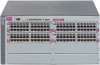
... Test LED Switch Modules and slots with Link and Mode LEDs for the Fans, Power Supplies, and Switch Modules LED Mode Select button and indicator LEDs hp procurve switch 5304xl J4850A Console Reset Clear Self Test Status 12ABCD Fan Power Modules Act FDx Max ! Example front description This illustration shows the 5348xl, but the...
... Test LED Switch Modules and slots with Link and Mode LEDs for the Fans, Power Supplies, and Switch Modules LED Mode Select button and indicator LEDs hp procurve switch 5304xl J4850A Console Reset Clear Self Test Status 12ABCD Fan Power Modules Act FDx Max ! Example front description This illustration shows the 5348xl, but the...
User Manual
Page 13
... test and initialization are in position 1. The normal state; On briefly at the beginning of the switch modules, an individual port, a power supply, or a fan. The normal operational state; As shipped, the switch has a single power supply in progress after the switch is not plugged in the position corresponding to the number, and the...
... test and initialization are in position 1. The normal state; On briefly at the beginning of the switch modules, an individual port, a power supply, or a fan. The normal operational state; As shipped, the switch has a single power supply in progress after the switch is not plugged in the position corresponding to the number, and the...

User Manual
Page 17
.... Because the switch can be installed in the back of the Switch 5300xl Series. AC power connector slot for proper power cord selection. .Disconnect AC power from this second power supply should be disconnected from the other supply. The switch redundant power supply is hot swappable, but, as indicated by the caution statement on when connected to a different...
.... Because the switch can be installed in the back of the Switch 5300xl Series. AC power connector slot for proper power cord selection. .Disconnect AC power from this second power supply should be disconnected from the other supply. The switch redundant power supply is hot swappable, but, as indicated by the caution statement on when connected to a different...

User Manual
Page 18
...or miniGBIC • 24-port 10/100-TX xl PoE Module (J8161A) -- which, when connected to a ProCurve 600 Redundant and External Power Supply(J8168A), can provide Power over multimode fiber-optic cable. • 16 port 10/100/1000Base-T xl Module (J4907A) -- For more information refer to 802.3af ...Caution 1-10 Switch Features The features of the Switch 5300xl Series include: ■ 4 or 8 slots for 100 Mbps networking over Ethernet (PoE) power to the ProCurve Switch xl Modules Installation Guide. • 1-port 10-GbE xl Module (J8988A) -- operates as an access controller (ProCurve Access ...
...or miniGBIC • 24-port 10/100-TX xl PoE Module (J8161A) -- which, when connected to a ProCurve 600 Redundant and External Power Supply(J8168A), can provide Power over multimode fiber-optic cable. • 16 port 10/100/1000Base-T xl Module (J4907A) -- For more information refer to 802.3af ...Caution 1-10 Switch Features The features of the Switch 5300xl Series include: ■ 4 or 8 slots for 100 Mbps networking over Ethernet (PoE) power to the ProCurve Switch xl Modules Installation Guide. • 1-port 10-GbE xl Module (J8988A) -- operates as an access controller (ProCurve Access ...
User Manual
Page 23
... Switch 5300xl Series can also be easier to install the modules first. Connect power to install your Switch 5300xl Series. 3. (Optional) Install second power supply (page 2-10). Make sure that the physical environment into a power source and observing that are supported. This is powered on a horizontal surface. Please see page 2-5 for installing a second, load-sharing...
... Switch 5300xl Series can also be easier to install the modules first. Connect power to install your Switch 5300xl Series. 3. (Optional) Install second power supply (page 2-10). Make sure that the physical environment into a power source and observing that are supported. This is powered on a horizontal surface. Please see page 2-5 for installing a second, load-sharing...

User Manual
Page 24
... 802.3ab standard which includes the Auto MDI/MDI-X feature. See the rest of this point, the switch is installed on any module or power supply slots. 2-4 WARNING Installation Precautions Follow these installation steps. At this chapter if you to use straight-through the switch's console interface. For more...-TX ports on the 10/100-TX and PoE xl Modules have the HP Auto-MDIX feature, and the 100/1000Base-T ports on page 2-18. These two features operate the same and allow any empty switch power supply slot. The rack or cabinet should be managed using a web browser or...
... 802.3ab standard which includes the Auto MDI/MDI-X feature. See the rest of this point, the switch is installed on any module or power supply slots. 2-4 WARNING Installation Precautions Follow these installation steps. At this chapter if you to use straight-through the switch's console interface. For more...-TX ports on the 10/100-TX and PoE xl Modules have the HP Auto-MDIX feature, and the 100/1000Base-T ports on page 2-18. These two features operate the same and allow any empty switch power supply slot. The rack or cabinet should be managed using a web browser or...

User Manual
Page 25
... and back of all devices installed on the same circuit as the switch and compare the total with the switch and power supply, be sure to use the power cord supplied with the switch and power supply. ■ When installing the switch, note that the AC outlet should be near the AC... power connectors. ■ Do not install the switch in case the switch must be powered off. ■ Ensure the switch does not overload the power circuits, wiring...
... and back of all devices installed on the same circuit as the switch and compare the total with the switch and power supply, be sure to use the power cord supplied with the switch and power supply. ■ When installing the switch, note that the AC outlet should be near the AC... power connectors. ■ Do not install the switch in case the switch must be powered off. ■ Ensure the switch does not overload the power circuits, wiring...

User Manual
Page 30
... Series Installing the Switch 5300xl Series Installation Procedures 3. (Optional) Install Second Power Supply A second, load-sharing redundant power supply (ProCurve Switch gl/xl/vl RPS, J4839A) can be removed with the power supply. 2-10 To provide true redundancy, this power supply BEFORE installing or removing the supply. The slot cover can be installed in the manual that comes with...
... Series Installing the Switch 5300xl Series Installation Procedures 3. (Optional) Install Second Power Supply A second, load-sharing redundant power supply (ProCurve Switch gl/xl/vl RPS, J4839A) can be removed with the power supply. 2-10 To provide true redundancy, this power supply BEFORE installing or removing the supply. The slot cover can be installed in the manual that comes with...

User Manual
Page 31
.... tighten the four screws Figure 2-4. The screws can be flush with either a flatbladed or Torx T-10 screwdriver. Be careful not to the switch. Insert the power supply into the opening, then slide it all the way in until it in place. Installing the Switch 5300xl Series Installation Procedures Installing the Switch 5300xl...
.... tighten the four screws Figure 2-4. The screws can be flush with either a flatbladed or Torx T-10 screwdriver. Be careful not to the switch. Insert the power supply into the opening, then slide it all the way in until it in place. Installing the Switch 5300xl Series Installation Procedures Installing the Switch 5300xl...
User Manual
Page 32
... Self Test After you have installed any modules and the optional second power supply, but before mounting the switch in its self test. Connecting the power cord The Switch 5300xl Series does not have installed a second power supply, repeat these procedures with the second power supply to verify it works correctly also. 1. Installing the Switch 5300xl Series...
... Self Test After you have installed any modules and the optional second power supply, but before mounting the switch in its self test. Connecting the power cord The Switch 5300xl Series does not have installed a second power supply, repeat these procedures with the second power supply to verify it works correctly also. 1. Installing the Switch 5300xl Series...
User Manual
Page 33
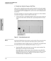
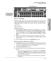
... module LEDs go off . ■ The port LEDs on the switch modules go on as the port is powered on the port. • If the ports are not connected to 2 minutes for each power supply installed, and one for all the switch chassis LEDs are on . You may see each port LED go... their normal operational mode: • If the ports are off . Installing the Switch 5300xl Series Installation Procedures Installing the Switch 5300xl Series switch chassis LEDs hp procurve switch 5304xl J4850A Console Reset Clear Self Test Status 12ABCD Fan...
... module LEDs go off . ■ The port LEDs on the switch modules go on as the port is powered on the port. • If the ports are not connected to 2 minutes for each power supply installed, and one for all the switch chassis LEDs are on . You may see each port LED go... their normal operational mode: • If the ports are off . Installing the Switch 5300xl Series Installation Procedures Installing the Switch 5300xl Series switch chassis LEDs hp procurve switch 5304xl J4850A Console Reset Clear Self Test Status 12ABCD Fan...

User Manual
Page 34
... 5308xl and Switch 5372xl each bracket is designed to the switch with three screws as a server cabinet. Mount the Switch After the modules and optional power supply are installed and you have verified the switch passes self test, you are ready to the switch 5308xl 2-14 The Switch 5300xl Series can be...
... 5308xl and Switch 5372xl each bracket is designed to the switch with three screws as a server cabinet. Mount the Switch After the modules and optional power supply are installed and you have verified the switch passes self test, you are ready to the switch 5308xl 2-14 The Switch 5300xl Series can be...

User Manual
Page 38
... not been disabled through " cable or "crossover" cable when the port is in the configurations of switch modules you have installed a redundant power supply module into a nearby properly grounded AC power source. If you have used the correct cable type for troubleshooting procedures. In general for all twisted-pair connections, the RJ-45...
... not been disabled through " cable or "crossover" cable when the port is in the configurations of switch modules you have installed a redundant power supply module into a nearby properly grounded AC power source. If you have used the correct cable type for troubleshooting procedures. In general for all twisted-pair connections, the RJ-45...

User Manual
Page 41
there is rebooted, the module will not operate and the Module Status LED for some basic configuration steps. If two power supplies are expanding the switch capability by any of the following methods: ■ Pressing the Reset button on the front of the switch. ■ ... replaced with a different type of module though, for example a 100/1000-T xl Module is installed in a slot where one was in the power cord (power cycle). You can properly initialize and configure the new module type. For more detailed information, refer to the Management and Configuration Guide which is on...
there is rebooted, the module will not operate and the Module Status LED for some basic configuration steps. If two power supplies are expanding the switch capability by any of the following methods: ■ Pressing the Reset button on the front of the switch. ■ ... replaced with a different type of module though, for example a 100/1000-T xl Module is installed in a slot where one was in the power cord (power cycle). You can properly initialize and configure the new module type. For more detailed information, refer to the Management and Configuration Guide which is on...

User Manual
Page 64
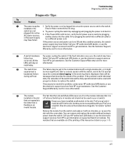
... pattern you see on your switch 2. LED Error Indicators LED Pattern Indicating Problems Diagnostic Tips Power Fault Self Test Module Status (one LED per module) Power Status (one LED per power supply) Fan Status Port Link Off with * * * * * * ➊ power cord plugged in the table for the diagnosis. † The flashing behavior is an on...
... pattern you see on your switch 2. LED Error Indicators LED Pattern Indicating Problems Diagnostic Tips Power Fault Self Test Module Status (one LED per module) Power Status (one LED per power supply) Fan Status Port Link Off with * * * * * * ➊ power cord plugged in the table for the diagnosis. † The flashing behavior is an on...
User Manual
Page 65
...Warranty card for more information. ➍ The module The fact that is plugged into active AC power sources, or the power supply may have failure has failed. All the from HP to get assistance. In the event log that the Link and Mode LEDs never are not compatible ...the problem, contact your HP-authorized LAN dealer, or use the electronic support services occurred. The modules that describe the extent of the problem. If the Power LED is with the LEDs Diagnostic Tips: Tip Number Problem Solution ➊ The power supplies 1. Try power cycling the switch by ...
...Warranty card for more information. ➍ The module The fact that is plugged into active AC power sources, or the power supply may have failure has failed. All the from HP to get assistance. In the event log that the Link and Mode LEDs never are not compatible ...the problem, contact your HP-authorized LAN dealer, or use the electronic support services occurred. The modules that describe the extent of the problem. If the Power LED is with the LEDs Diagnostic Tips: Tip Number Problem Solution ➊ The power supplies 1. Try power cycling the switch by ...

User Manual
Page 67
... their self test, will operate normally. ➑ A fault condition Try removing and reinstalling the power supply. The flashing continues until you will be able to use the electronic support services from HP to replace the mini-GBIC or the module. Unsupported mini-GBICs will have failed. the flashing... reinstalling the supply. The mini-GBICs are also tested when they are listed in this table, each network port is disconnected from the switch. has been detected Caution: Ensure the AC power cord is also tested. Call your HP-authorized LAN dealer, or use the port, you ...
... their self test, will operate normally. ➑ A fault condition Try removing and reinstalling the power supply. The flashing continues until you will be able to use the electronic support services from HP to replace the mini-GBIC or the module. Unsupported mini-GBICs will have failed. the flashing... reinstalling the supply. The mini-GBICs are also tested when they are listed in this table, each network port is disconnected from the switch. has been detected Caution: Ensure the AC power cord is also tested. Call your HP-authorized LAN dealer, or use the port, you ...

User Manual
Page 75
... volts 200-240 volts Maximum current: 8.2 A 3.8 A Frequency range: 50/60 Hz 50/60 Hz Each installed J8161A module may draw 408W@50V from an external power supply Environmental Temperature: Relative humidity: (non-condensing) Maximum altitude: Operating 5°C to 40°C (41°F to 104°F) 15% to 80% at 40°C (104...
... volts 200-240 volts Maximum current: 8.2 A 3.8 A Frequency range: 50/60 Hz 50/60 Hz Each installed J8161A module may draw 408W@50V from an external power supply Environmental Temperature: Relative humidity: (non-condensing) Maximum altitude: Operating 5°C to 40°C (41°F to 104°F) 15% to 80% at 40°C (104...

User Manual
Page 99
... cable specifications ... B-2 1000Base-LH connections ... 2-6 fiber-optic cable specifications ... B-2 10Base-T cable specifications ... B-2 twisted-pair cable specifications ... B-6, B-8 HP Auto-MDIX feature ... B-2 connecting cables to switch ports ... 2-18 effects of switch description ... 1-9 power connector ... 1-9 slot for redundant power supply ... 1-9 basic connectivity, example topology ... 2-22 basic switch configuration IP address ... 3-3 manager password ... 3-2 subnet mask ... 3-3 Switch Setup screen...
... cable specifications ... B-2 1000Base-LH connections ... 2-6 fiber-optic cable specifications ... B-2 10Base-T cable specifications ... B-2 twisted-pair cable specifications ... B-6, B-8 HP Auto-MDIX feature ... B-2 connecting cables to switch ports ... 2-18 effects of switch description ... 1-9 power connector ... 1-9 slot for redundant power supply ... 1-9 basic connectivity, example topology ... 2-22 basic switch configuration IP address ... 3-3 manager password ... 3-2 subnet mask ... 3-3 Switch Setup screen...