Packer Arm Installation
Page 11
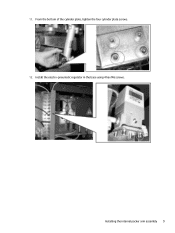
11. Installing the internal packer arm assembly 9 From the bottom of the cylinder plate, tighten the four cylinder plate screws. 12. Install the electro-pneumatic regulator in the base using 4 hex M6 screws.
11. Installing the internal packer arm assembly 9 From the bottom of the cylinder plate, tighten the four cylinder plate screws. 12. Install the electro-pneumatic regulator in the base using 4 hex M6 screws.

Packer Arm Installation
Page 17
b. Manually raise the lower packer arm cylinder until it touches the rewinder expanding shaft cylinder. Use a level to ensure that the lower packer arm cylinder is leveled. To align the packer arm idler cylinder, use the external packer arm bolts as push and pull mechanisms. Installing the external packer arm assembly 15 d. c. Use a filler gauge to ensure that the two cylinders are horizontally parallel and vertically parallelUse the following points: two opposite end points and one middle point. a.
b. Manually raise the lower packer arm cylinder until it touches the rewinder expanding shaft cylinder. Use a level to ensure that the lower packer arm cylinder is leveled. To align the packer arm idler cylinder, use the external packer arm bolts as push and pull mechanisms. Installing the external packer arm assembly 15 d. c. Use a filler gauge to ensure that the two cylinders are horizontally parallel and vertically parallelUse the following points: two opposite end points and one middle point. a.
Packer Arm Installation
Page 19
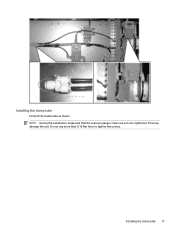
NOTE: During the installation, make sure that the pressure gauge screws are not over-tightened. Installing the clamp tube Connect the clamp tube as shown. Do not use more than 0.16 Nm force to tighten the screws. Installing the clamp tube 17 This may damage the unit.
NOTE: During the installation, make sure that the pressure gauge screws are not over-tightened. Installing the clamp tube Connect the clamp tube as shown. Do not use more than 0.16 Nm force to tighten the screws. Installing the clamp tube 17 This may damage the unit.
Packer Arm Installation
Page 29
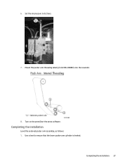
6. Use a level to 0.2 bars. 7. Completing the installation Level the external packer arm assembly, as follows: 1. Set the air pressure to ensure that the lower packer arm cylinder is leveled. Completing the installation 27 Turn on the pressStart the press software. Mount the packer arm threading label (p/n CA396-00880) onto the rewinder. 8.
6. Use a level to 0.2 bars. 7. Completing the installation Level the external packer arm assembly, as follows: 1. Set the air pressure to ensure that the lower packer arm cylinder is leveled. Completing the installation 27 Turn on the pressStart the press software. Mount the packer arm threading label (p/n CA396-00880) onto the rewinder. 8.

Packer Arm Installation
Page 30
Use the following points: two opposite end points and one middle point. 4. Use a feeler gauge to ensure that the two cylinders are horizontally parallel and vertically parallel. To level and align the packer arm idler cylinder, use the external packer arm bolts and bushings as push and pull mechanisms. 28 Chapter 2 Procedures 2. Manually raise the lower packer arm cylinder until it touches the rewinder expanding shaft cylinder. 3.
Use the following points: two opposite end points and one middle point. 4. Use a feeler gauge to ensure that the two cylinders are horizontally parallel and vertically parallel. To level and align the packer arm idler cylinder, use the external packer arm bolts and bushings as push and pull mechanisms. 28 Chapter 2 Procedures 2. Manually raise the lower packer arm cylinder until it touches the rewinder expanding shaft cylinder. 3.
Rewinder Service
Page 6
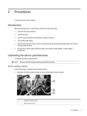
...). Turn off or disconnect the compressed air supply to CA493-00080 - Shut down the press software. 2. Turn off the water supply. 5. Disconnect the press from all sources of electrical power by using the Main Supply Disconnect switch mounted near the press. 6. Introduction When performing service on the rewinder connector plate. 1 Rewinder connector's plate 2 Molex...
...). Turn off or disconnect the compressed air supply to CA493-00080 - Shut down the press software. 2. Turn off the water supply. 5. Disconnect the press from all sources of electrical power by using the Main Supply Disconnect switch mounted near the press. 6. Introduction When performing service on the rewinder connector plate. 1 Rewinder connector's plate 2 Molex...
Rewinder Service
Page 7
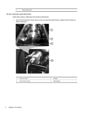
Use a 2.0 mm Hex key to loosen the set screw securing the potentiometer coupling to calibrate at the rewinder potentiometer. 1. 3 Potentiometer cable At the rewinder potentiometer Follow these steps to the rotating arm shaft of the dancer. 1 Dancer arm shaft 2 Hex 2.0 mm set screw 3 Coupling 4 Potentiometer 4 Chapter 2 Procedures
Use a 2.0 mm Hex key to loosen the set screw securing the potentiometer coupling to calibrate at the rewinder potentiometer. 1. 3 Potentiometer cable At the rewinder potentiometer Follow these steps to the rotating arm shaft of the dancer. 1 Dancer arm shaft 2 Hex 2.0 mm set screw 3 Coupling 4 Potentiometer 4 Chapter 2 Procedures
Rewinder Service
Page 14
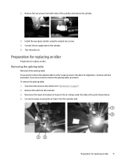
...point shown below. 4. Cut any tie wraps securing the air tubes from the rewinder. 3. Shut down the press as described in order to gain access to replace an idler. Turn the press on page 3". 2. Disconnect the input and output air hoses to the cylinder. 6. If you need to remove...alignment, continue with this procedure. Preparation for replacing an idler Preparation to the idlers for replacing an idler 11 3. Install the new glass cylinder using the original two screws. 5. If you do not need to remove the splicing table in the "Introduction on . Remove the two screws from...
...point shown below. 4. Cut any tie wraps securing the air tubes from the rewinder. 3. Shut down the press as described in order to gain access to replace an idler. Turn the press on page 3". 2. Disconnect the input and output air hoses to the cylinder. 6. If you need to remove...alignment, continue with this procedure. Preparation for replacing an idler Preparation to the idlers for replacing an idler 11 3. Install the new glass cylinder using the original two screws. 5. If you do not need to remove the splicing table in the "Introduction on . Remove the two screws from...
Rewinder Service
Page 16
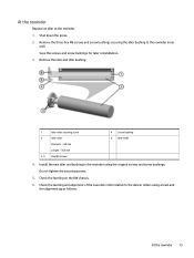
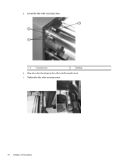
Shut down the press. 2. Remove the three hex M6 screws and screw bushings securing the idler bushing to the rewinder using a level and the alignment jig as follows: At the rewinder 13 Do not tighten the securing screws. 5. Remove the idler and idler bushing. 1 Idler roller ...Length - 365 mm 3, 5 Hex M6 screws 4 Screw bushing 6 Idler shaft 4. Check the leveling and alignment of the new idler roller relative to the dancer rollers using the original screws and screw bushings. At the rewinder Replace an idler at the rewinder. 1. Install the new idler and bushing to the rewinder inner...
Shut down the press. 2. Remove the three hex M6 screws and screw bushings securing the idler bushing to the rewinder using a level and the alignment jig as follows: At the rewinder 13 Do not tighten the securing screws. 5. Remove the idler and idler bushing. 1 Idler roller ...Length - 365 mm 3, 5 Hex M6 screws 4 Screw bushing 6 Idler shaft 4. Check the leveling and alignment of the new idler roller relative to the dancer rollers using the original screws and screw bushings. At the rewinder Replace an idler at the rewinder. 1. Install the new idler and bushing to the rewinder inner...
Rewinder Service
Page 17
c. Loosen the idler roller securing screws. 1, 2 Securing screws 3 Bushings b. Tighten the idler roller securing screws. 14 Chapter 2 Procedures a. Align the roller's bushings to the roller's shaft using the level.
c. Loosen the idler roller securing screws. 1, 2 Securing screws 3 Bushings b. Tighten the idler roller securing screws. 14 Chapter 2 Procedures a. Align the roller's bushings to the roller's shaft using the level.
Rewinder Service
Page 18
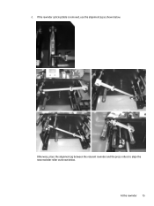
If the rewinder splicing table is removed, use the alignment jig as shown below . Otherwise, place the alignment jig between the relevant rewinder and the press rollers to align the new rewinder roller as shown below . At the rewinder 15 d.
If the rewinder splicing table is removed, use the alignment jig as shown below . Otherwise, place the alignment jig between the relevant rewinder and the press rollers to align the new rewinder roller as shown below . At the rewinder 15 d.
Rewinder Service
Page 19
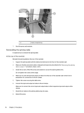
...held next to reinstall the splicing table. At the rear of the rewinder wall. 2. Tighten the screws securing the table arms. 6. Restart the press. 16 Chapter 2 Procedures Reinstalling the splicing table It explains how to the front of the rewinder Reinstall the splicing table at the clamps. 7....procedure, steps5. and 6.. 3. Make sure that the pneumatic plate is released and lowered as described in preparation for connections to the splicing table using tie wraps. 8. Make sure to route all input and output air tubes from the rear of the rewinder. 1. Install the six sets of...
...held next to reinstall the splicing table. At the rear of the rewinder wall. 2. Tighten the screws securing the table arms. 6. Restart the press. 16 Chapter 2 Procedures Reinstalling the splicing table It explains how to the front of the rewinder Reinstall the splicing table at the clamps. 7....procedure, steps5. and 6.. 3. Make sure that the pneumatic plate is released and lowered as described in preparation for connections to the splicing table using tie wraps. 8. Make sure to route all input and output air tubes from the rear of the rewinder. 1. Install the six sets of...
Rewinder Service
Page 20
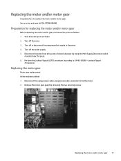
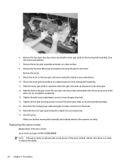
Turn off or disconnect the compressed air supply to the press. 4. Perform the Lockout-Tagout (LOTO) procedure (according to replace the motor and/or motor gear. Replacing the motor gear Motor gear replacement. Servo motor and ... replacing the motor and/or gear, shut down the press software. 2. Turn off the water supply. 5. Turn off the press. 3. Remove the motor gear guard by using the Main Supply Disconnect switch mounted near the press. 6. Shut down the press as follows: 1. Lockout-Tagout Procedures). Disconnect the press from the motor. 2. Replacing the motor and/or...
Turn off or disconnect the compressed air supply to the press. 4. Perform the Lockout-Tagout (LOTO) procedure (according to replace the motor and/or motor gear. Replacing the motor gear Motor gear replacement. Servo motor and ... replacing the motor and/or gear, shut down the press software. 2. Turn off the water supply. 5. Turn off the press. 3. Remove the motor gear guard by using the Main Supply Disconnect switch mounted near the press. 6. Shut down the press as follows: 1. Lockout-Tagout Procedures). Disconnect the press from the motor. 2. Replacing the motor and/or...
Rewinder Service
Page 21
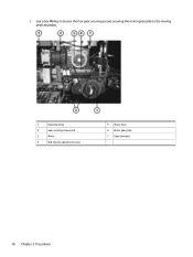
Use a hex M8 key to loosen the four gear securing screws securing the motor gear plate to the moving shelf assembly. 1 Rewinder drive 2 Gear securing screws (x4) 3 Motor 4 Belt tension adjustment screw 5 Motor drive 6 Motor gear plate 7 Gear drive belt 18 Chapter 2 Procedures 3.
Use a hex M8 key to loosen the four gear securing screws securing the motor gear plate to the moving shelf assembly. 1 Rewinder drive 2 Gear securing screws (x4) 3 Motor 4 Belt tension adjustment screw 5 Motor drive 6 Motor gear plate 7 Gear drive belt 18 Chapter 2 Procedures 3.
Rewinder Service
Page 23
...motor gear assembly in its original position on a clean surface. 8. Start the press. Mount the motor to the motor. Insert the four gear securing screws and .... Remove the four Hex M6 screws and washers securing the gear to the new gear and secure using the original two securing screws. 17. Remove the four gear securing screws securing the motor gear plate...cable and green encoder connectors to secure the motor gear plate on the gear. Reinstall the motor gear guard using the original screws and washers. 10. Tighten all four gear securing screws to the motor. 16. Save ...
...motor gear assembly in its original position on a clean surface. 8. Start the press. Mount the motor to the motor. Insert the four gear securing screws and .... Remove the four Hex M6 screws and washers securing the gear to the new gear and secure using the original two securing screws. 17. Remove the four gear securing screws securing the motor gear plate...cable and green encoder connectors to secure the motor gear plate on the gear. Reinstall the motor gear guard using the original screws and washers. 10. Tighten all four gear securing screws to the motor. 16. Save ...
Rewinder Service
Page 38
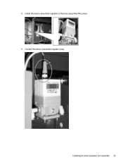
Connect the electro-pneumatic regulator plug. Install the electro-pneumatic regulator in the base using 4 hex M6 screws. 13. 12. Installing the internal packer arm assembly 35
Connect the electro-pneumatic regulator plug. Install the electro-pneumatic regulator in the base using 4 hex M6 screws. 13. 12. Installing the internal packer arm assembly 35

Rewinder Service
Page 43
Manually raise the lower packer arm cylinder until it touches the rewinder expanding shaft cylinder. Install the external packer arm assembly on the base. 1 Base 2 External packer arm assembly 3. b. To level the external packer arm assembly: a. Use a level to ensure that the lower packer arm cylinder is leveled. c. Use a filler gauge to ensure that the two cylinders are horizontally parallel and vertically parallel Use the following points: two opposite end points and one middle point. 40 Chapter 2 Procedures 2.
Manually raise the lower packer arm cylinder until it touches the rewinder expanding shaft cylinder. Install the external packer arm assembly on the base. 1 Base 2 External packer arm assembly 3. b. To level the external packer arm assembly: a. Use a level to ensure that the lower packer arm cylinder is leveled. c. Use a filler gauge to ensure that the two cylinders are horizontally parallel and vertically parallel Use the following points: two opposite end points and one middle point. 40 Chapter 2 Procedures 2.
Rewinder Service
Page 44
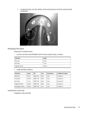
d. Install the tubes as push and pull mechanisms. Preparing the tubes Preparation to install the tubes. 1. To align the packer arm idler cylinder, use the external packer arm bolts as follows: Length 55 mm 11 mm 120 mm Tube Name Main tube Clamp tube Short tube Engagement tube Disengagement ...
d. Install the tubes as push and pull mechanisms. Preparing the tubes Preparation to install the tubes. 1. To align the packer arm idler cylinder, use the external packer arm bolts as follows: Length 55 mm 11 mm 120 mm Tube Name Main tube Clamp tube Short tube Engagement tube Disengagement ...
Rewinder Service
Page 59
... install the new packer arm as described in the "Installing a new packer arm on page 28" . Use air pressure to set the packer arm to the expanding shaft using the original screws. b. If the packer arm idler roller does not align correctly parallel to the expanding shaft,...b. Installing the new packer arm Installation of securing screws Rear wall 7, 9 Securing screws 8 Clamp 11 Idler 2. Mount the new clamp and secure using a level and a feeler gauge. To replace the clamp within the packer arm adjustable external assembly: a. After the packer arm is parallel relative to ...
... install the new packer arm as described in the "Installing a new packer arm on page 28" . Use air pressure to set the packer arm to the expanding shaft using the original screws. b. If the packer arm idler roller does not align correctly parallel to the expanding shaft,...b. Installing the new packer arm Installation of securing screws Rear wall 7, 9 Securing screws 8 Clamp 11 Idler 2. Mount the new clamp and secure using a level and a feeler gauge. To replace the clamp within the packer arm adjustable external assembly: a. After the packer arm is parallel relative to ...
Rewinder Service
Page 60
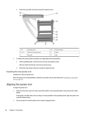
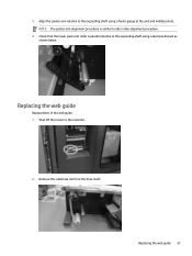
NOTE: The packer arm alignment procedure is parallel relative to the rewinder. 2. Replacing the web guide 57 Remove the substrate roll from the drive shaft. Align the packer arm relative to idler roller alignment procedure. 4. Shut off the power to the expanding shaft using a feeler gauge at the end and middle points. Replacing the web guide Replacement of the web guide. 1. Check that the lower pack arm roller is similar to the expanding shaft using a level positioned as shown below. 3.
NOTE: The packer arm alignment procedure is parallel relative to the rewinder. 2. Replacing the web guide 57 Remove the substrate roll from the drive shaft. Align the packer arm relative to idler roller alignment procedure. 4. Shut off the power to the expanding shaft using a feeler gauge at the end and middle points. Replacing the web guide Replacement of the web guide. 1. Check that the lower pack arm roller is similar to the expanding shaft using a level positioned as shown below. 3.

