
Packer Arm Installation
Page 17
b. Manually raise the lower packer arm cylinder until it touches the rewinder expanding shaft cylinder. Use a filler gauge to ensure that the two cylinders are horizontally parallel and vertically parallelUse the following points: two opposite end points and one middle point. d. a. To align the packer arm idler cylinder, use the external packer arm bolts as push and pull mechanisms. Installing the external packer arm assembly 15 Use a level to ensure that the lower packer arm cylinder is leveled. c.
b. Manually raise the lower packer arm cylinder until it touches the rewinder expanding shaft cylinder. Use a filler gauge to ensure that the two cylinders are horizontally parallel and vertically parallelUse the following points: two opposite end points and one middle point. d. a. To align the packer arm idler cylinder, use the external packer arm bolts as push and pull mechanisms. Installing the external packer arm assembly 15 Use a level to ensure that the lower packer arm cylinder is leveled. c.

Packer Arm Installation
Page 30
Use a feeler gauge to ensure that the two cylinders are horizontally parallel and vertically parallel. Use the following points: two opposite end points and one middle point. 4. Manually raise the lower packer arm cylinder until it touches the rewinder expanding shaft cylinder. 3. To level and align the packer arm idler cylinder, use the external packer arm bolts and bushings as push and pull mechanisms. 28 Chapter 2 Procedures 2.
Use a feeler gauge to ensure that the two cylinders are horizontally parallel and vertically parallel. Use the following points: two opposite end points and one middle point. 4. Manually raise the lower packer arm cylinder until it touches the rewinder expanding shaft cylinder. 3. To level and align the packer arm idler cylinder, use the external packer arm bolts and bushings as push and pull mechanisms. 28 Chapter 2 Procedures 2.
Rewinder Service
Page 9
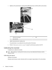
... the dancer and the ultrasonic sensor. Perform "Calibrating the rewinder on page 6" on page 9 to calibrate the rewinder. Calibrating the dancer Calibration of the dancer. 6. Manually rotate the dancer counter-clockwise until the DVM display value is now calibrated to the central position of the dancer. 4. Slightly turn the potentiometer coupling...
... the dancer and the ultrasonic sensor. Perform "Calibrating the rewinder on page 6" on page 9 to calibrate the rewinder. Calibrating the dancer Calibration of the dancer. 6. Manually rotate the dancer counter-clockwise until the DVM display value is now calibrated to the central position of the dancer. 4. Slightly turn the potentiometer coupling...
Rewinder Service
Page 11
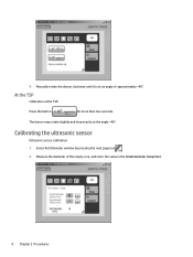
Calibrating the ultrasonic sensor Ultrasonic sensor calibration. 1. Select Roll Diameter window by pressing the next page icon . 2. The dancer may rotate slightly and stop exactly at the TSP. Press the button for more than two seconds. Measure the diameter of approximately +40°. 4. At the TSP Calibration at the angle +40°. Manually rotate the dancer clockwise until it is at an angle of the empty core, and enter the value in the Small diameter Setup field. 8 Chapter 2 Procedures
Calibrating the ultrasonic sensor Ultrasonic sensor calibration. 1. Select Roll Diameter window by pressing the next page icon . 2. The dancer may rotate slightly and stop exactly at the TSP. Press the button for more than two seconds. Measure the diameter of approximately +40°. 4. At the TSP Calibration at the angle +40°. Manually rotate the dancer clockwise until it is at an angle of the empty core, and enter the value in the Small diameter Setup field. 8 Chapter 2 Procedures

Rewinder Service
Page 43
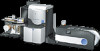
2. To level the external packer arm assembly: a. Use a filler gauge to ensure that the two cylinders are horizontally parallel and vertically parallel Use the following points: two opposite end points and one middle point. 40 Chapter 2 Procedures b. Manually raise the lower packer arm cylinder until it touches the rewinder expanding shaft cylinder. c. Install the external packer arm assembly on the base. 1 Base 2 External packer arm assembly 3. Use a level to ensure that the lower packer arm cylinder is leveled.
2. To level the external packer arm assembly: a. Use a filler gauge to ensure that the two cylinders are horizontally parallel and vertically parallel Use the following points: two opposite end points and one middle point. 40 Chapter 2 Procedures b. Manually raise the lower packer arm cylinder until it touches the rewinder expanding shaft cylinder. c. Install the external packer arm assembly on the base. 1 Base 2 External packer arm assembly 3. Use a level to ensure that the lower packer arm cylinder is leveled.
Rewinder Service
Page 64
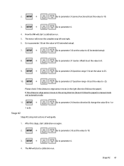
... the RW will start calibration run . 5. The motor will move the complete way left and right. 6. Please check if the ultrasonic edge sensor moves in manual mode and automatic mode: 11. Go to parameter 24 (motion direction) & change the value (0 to 1 or 1 to 10. 3. Go to parameter 3 & set the value to...
... the RW will start calibration run . 5. The motor will move the complete way left and right. 6. Please check if the ultrasonic edge sensor moves in manual mode and automatic mode: 11. Go to parameter 24 (motion direction) & change the value (0 to 1 or 1 to 10. 3. Go to parameter 3 & set the value to...

Rewinder Service
Page 84
Measure the dimensions of the ramp at least 2 more times for all sample runs. 3. manually unwind to the floor. 6. After reaching the floor, the roll will slow down the ramp. 7. Repeat the test at predetermined spot, while holding the unwound ...
Measure the dimensions of the ramp at least 2 more times for all sample runs. 3. manually unwind to the floor. 6. After reaching the floor, the roll will slow down the ramp. 7. Repeat the test at predetermined spot, while holding the unwound ...


